EP0978742B1 - Besfestigungsvorrichtung für eine optische Faser zur Kopplung mit einem optischen Kommunikationsmodul - Google Patents
Besfestigungsvorrichtung für eine optische Faser zur Kopplung mit einem optischen Kommunikationsmodul Download PDFInfo
- Publication number
- EP0978742B1 EP0978742B1 EP99305630A EP99305630A EP0978742B1 EP 0978742 B1 EP0978742 B1 EP 0978742B1 EP 99305630 A EP99305630 A EP 99305630A EP 99305630 A EP99305630 A EP 99305630A EP 0978742 B1 EP0978742 B1 EP 0978742B1
- Authority
- EP
- European Patent Office
- Prior art keywords
- optical fiber
- fixing device
- slot
- leaf spring
- case
- Prior art date
- Legal status (The legal status is an assumption and is not a legal conclusion. Google has not performed a legal analysis and makes no representation as to the accuracy of the status listed.)
- Expired - Lifetime
Links
- 239000013307 optical fiber Substances 0.000 title claims description 151
- 230000003287 optical effect Effects 0.000 title description 11
- 238000004891 communication Methods 0.000 title description 10
- 230000008878 coupling Effects 0.000 title description 2
- 238000010168 coupling process Methods 0.000 title description 2
- 238000005859 coupling reaction Methods 0.000 title description 2
- 210000000078 claw Anatomy 0.000 claims description 45
- 238000003780 insertion Methods 0.000 claims description 22
- 230000037431 insertion Effects 0.000 claims description 22
- 238000000034 method Methods 0.000 description 5
- 230000001154 acute effect Effects 0.000 description 4
- 239000011347 resin Substances 0.000 description 4
- 229920005989 resin Polymers 0.000 description 4
- 239000000835 fiber Substances 0.000 description 3
- 229910000906 Bronze Inorganic materials 0.000 description 2
- 238000005452 bending Methods 0.000 description 2
- 239000010974 bronze Substances 0.000 description 2
- KUNSUQLRTQLHQQ-UHFFFAOYSA-N copper tin Chemical compound [Cu].[Sn] KUNSUQLRTQLHQQ-UHFFFAOYSA-N 0.000 description 2
- 230000000881 depressing effect Effects 0.000 description 2
- 239000002184 metal Substances 0.000 description 2
- 229910001220 stainless steel Inorganic materials 0.000 description 2
- 239000010935 stainless steel Substances 0.000 description 2
- OAICVXFJPJFONN-UHFFFAOYSA-N Phosphorus Chemical compound [P] OAICVXFJPJFONN-UHFFFAOYSA-N 0.000 description 1
- 230000015572 biosynthetic process Effects 0.000 description 1
- 239000011521 glass Substances 0.000 description 1
- BHEPBYXIRTUNPN-UHFFFAOYSA-N hydridophosphorus(.) (triplet) Chemical compound [PH] BHEPBYXIRTUNPN-UHFFFAOYSA-N 0.000 description 1
- 239000000463 material Substances 0.000 description 1
Images




Classifications
-
- G—PHYSICS
- G02—OPTICS
- G02B—OPTICAL ELEMENTS, SYSTEMS OR APPARATUS
- G02B6/00—Light guides; Structural details of arrangements comprising light guides and other optical elements, e.g. couplings
- G02B6/24—Coupling light guides
- G02B6/36—Mechanical coupling means
- G02B6/3628—Mechanical coupling means for mounting fibres to supporting carriers
- G02B6/3632—Mechanical coupling means for mounting fibres to supporting carriers characterised by the cross-sectional shape of the mechanical coupling means
- G02B6/3644—Mechanical coupling means for mounting fibres to supporting carriers characterised by the cross-sectional shape of the mechanical coupling means the coupling means being through-holes or wall apertures
-
- G—PHYSICS
- G02—OPTICS
- G02B—OPTICAL ELEMENTS, SYSTEMS OR APPARATUS
- G02B6/00—Light guides; Structural details of arrangements comprising light guides and other optical elements, e.g. couplings
- G02B6/24—Coupling light guides
- G02B6/36—Mechanical coupling means
- G02B6/38—Mechanical coupling means having fibre to fibre mating means
- G02B6/3807—Dismountable connectors, i.e. comprising plugs
- G02B6/3869—Mounting ferrules to connector body, i.e. plugs
-
- G—PHYSICS
- G02—OPTICS
- G02B—OPTICAL ELEMENTS, SYSTEMS OR APPARATUS
- G02B6/00—Light guides; Structural details of arrangements comprising light guides and other optical elements, e.g. couplings
- G02B6/24—Coupling light guides
- G02B6/42—Coupling light guides with opto-electronic elements
- G02B6/4201—Packages, e.g. shape, construction, internal or external details
- G02B6/4248—Feed-through connections for the hermetical passage of fibres through a package wall
Definitions
- the present invention relates to an optical fiber fixing device for optically coupling an optical fiber with an optical communication module.
- an optical communication module is constructed such that a laser diode, a lens and an optical fiber are combined and.integrally formed to each other, the laser beams radiated from the laser diode are collected through the lens and optically coupled within the optical fiber.
- a system in which the optical fiber can be inserted into or removed from the main body of the optical communication module is called a receptacle type.
- Fig.11 is a partially sectional view for showing a configuration of an optical fiber fixing device 150 constituting the prior art optical communication module.
- the prior art optical fiber fixing device 150 is comprised of a cylindrical case 151, a substantially cylindrical sleeve 152 stored in the case 151 and a resilient metallic leaf spring 153.
- the case 151 is provided with a front wall 154 having a circular fixing hole 154a. A side opposing against the front wall 154 of the case 151 is provided with a rear wall (not shown) . In addition, the case 151 is provided with a side wall 151b connecting the front wall 154 with the rear wall.
- the rear wall 151b is formed with an engaging step 155 projected inwardly between the front wall 154 and the rear wall at its inner circumferential surface. Then, the formation of the engaging step 155 causes a space between the front wall 154 and the engaging step 155 to become a space 156.
- a groove 157 extending along an inner circumferential surface of the side wall 151b.
- a cylindrical sleeve 152 is formed with a fiber insertion hole 161 passing in the sleeve around its center.
- a part around the insertion hole 161 is applied as an external side wall 160 and its one end is formed with a flange-like knob 162 projected outwardly from the external side wall 160.
- the other end of it is formed with a metering section 163.
- the end part of the knob section 162 of the external side wall 160 facing against the fiber insertion hole 161 is formed with a tapered part 161a.
- a substantially central part between the knob 162 and the metering section 163 is formed with a stopper 164 protruded out of the external circumferential surface in an outward direction. Then, the sleeve 152 is stored in the case 151 and the knob 162 is protruded out of the fixing hole 154a of the case 151 in an outward direction.
- the stopper 164 for the sleeve 152 is movably arranged and assembled within the space 156 between the front wall 154 and the engaging step 155.
- the leaf spring 153 is comprised of a circular thin metallic base plate 165 and a substantially circular inner opening 166 recessed and formed at its central part.
- An edge part of the inner opening 166 of the base plate 165 is formed with a plurality of tongue-like resilient lock claws 167 formed to be extended inwardly.
- lock claws 167 are formed with their sectional surfaces being bent from the edge of the inner opening 166 at the base plate 165 on a plane of the base plate in the figure.
- the extremity end of each of the lock claws 167 is formed such that its sectional surface in a direction of plate thickness may form an acute angle.
- the optical fiber 100 is comprised of a core 100a made of optical wave guide of glass or plastic material and the like and a clad 100b covering the core 100a with resin. Then, the optical fiber 100 is arranged within the sleeve 152 of the case 151. At the end part of the optical fiber 100 is arranged a laser diode (not shown) or the like. Then, the laser beam is incident from this laser diode to the end part of this optical fiber 100.
- the optical fiber 100 When the optical fiber 100 is inserted into the sleeve 152 from outside with the tapered portion 161a being applied as a guide, the optical fiber advances forward with its position being restricted by the fiber insertion hole 161, the extremity end of each of the lock claws 167 is pushed out in an inserting direction, a clearance between each of the extremity ends is widened and the optical fiber 100 is inserted smoothly into the case 151 while it is being abutted against the outer circumferential surface of the covering section 100b of the optical fiber 100.
- the covering part 100b of the optical fiber 100 is resiliently pushed by the extremity end of the lock claw 167.
- the extremity end of the stopper piece 167 formed in an acute angle bites into the outer circumferential surface of the covering part 100b so as to prevent the optical fiber from being pulled out of it.
- laser beam incident to one end of the core 100a of the optical fiber 100 from the laser diode is transmitted within the core 100a and is outputted at the other end thereof.
- the sleeve 152 is pushed within the fixing hole 154a in a direction opposite to its pulling-out direction. That is, the knob 162 is held in such a way that it can be pushed against the optical fiber 100 in a direction parallel to it and then it is pushed until the stopper 164 abuts against the engaging step 155.
- a metered part 163 formed at the extremity end of the sleeve 152 pushes wide the extremity end of each of the lock claws 167 and a fitted state of the extremity end of the lock claw 167 into the covering part 100b of the optical fiber 100 and its held state are released. In this way, it is possible that the optical fiber 100 is pulled out of the case 151 under a state in which the sleeve 152 is being pushed into the case 151.
- Document US-4 986 625 discloses an optical fiber connector with a retainer formed from a leaf spring with lock claws engaging the optical fiber.
- the leaf spring is inserted into the connector in a direction perpendicular to the inserting direction of the optical fiber.
- Document EP-0 335 367 discloses an attaching structure for an optical fiber with an optical fiber retainer with an insertion hole and a slot, which is narrowed and widened by a pressing screw in order to engage and disengage the optical fiber.
- the present invention has been invented in reference to the aforesaid problems and it is an object of the present invention to provide an optical fiber fixing device in which a thickness of the case in respect to an inserting and pulling-out direction of the optical fiber is made thin to form a small-sized and thin type device.
- an optical fiber fixing device As a first solving means for solving the aforesaid problems, there is provided an optical fiber fixing device according to claim 1.
- Fig.1 is a perspective view for showing a schematic configuration of an optical fiber fixing device 10 of a first preferred embodiment of the present invention.
- Fig.2 is a sectional view taken along a line 2-2 of the optical fiber fixing device 10 in Fig.1 as viewed from its arrow direction.
- the optical fiber fixing device 10 is provided with a substantially rectangular case 11 formed by a metal of relative thin thickness or resin showing a high rigidity, a metallic thin leaf spring 12 having a rectangular shape, an operating button 13 abutted against this leaf spring 12 is attached to it and fixed to it.
- the case 11 is provided with a wide and flat front wall 14 (at the front side in Fig.1). Further, there is provided a rear wall 15 (at a rear side in Fig.1) at its rear surface in opposition to the front wall 14.
- each of a first side wall 16a and a second side wall 16b in an upward or downward direction of the four surfaces connecting the parallel front wall 14 and rear wall 15, respectively.
- the case 11 is provided with, at its inner side, a rectangular-shaped wide cavity 11a in such a way that its wide part may become in parallel with the front wall 14 and the rear wall 15.
- An insertion hole 17 for the optical fiber is punched out and formed in a circular shape at the central part of the front wall 14.
- a smaller circular fixing hole 20 than the insertion hole 17 is passed and formed at the front wall 14 in such a way that it may be positioned between the insertion hole 17 and the first side wall 16a.
- a column-like space 23 having a larger diameter than that of the fixing hole 20 is formed at a central part (within a plate thickness of the front wall 14) of the fixing hole 20. Further, it is available that the space 23 is formed to be directly faced (exposed) against the cavity 11a.
- the rear wall 15 is formed with a substantially circular opening 22 at the central part of it in such a way that the opening may be oppositely faced against the insertion hole 17 of the front wall 14.
- Fig.3 is a perspective view for showing the leaf spring 12 constituting the optical fiber fixing device 10.
- the leaf spring 12 is made such that a metallic plate member made of stainless steel or phosphor bronze is formed to have a resiliency.
- the leaf spring 12 is formed with a base plate 12a and a through-pass hole 25 punched at its central part and formed in a circular shape.
- Four tongue-like resilient lock claws 26 extended and arranged inwardly are equally spaced apart at an edge part of the base plate 12a at the through-pass hole 25.
- lock claws 26 are bent and formed on the surface of the base plate 12a from the edge part of the through-pass hole 25 in the base plate 12a at their sectional surfaces as viewed in the figure.
- the extremity end 35 of the lock claw 26 is crushed and formed in such a way that a sectional area in its plate thickness direction may become an acute angle.
- the leaf spring 12 is formed with a first slot 27 recessed in a linear shape so as to reach the upper part of the through-pass hole 25 and a second slot 28 recessed in an angular-shape so as to reach the lower part of the through-pass hole 25, respectively.
- the leaf spring 12 may easily be flexed by the first and second slots 27, 28, respectively.
- the leaf spring 12 constructed as described above in the cavity 11a of the case 11 as shown in Fig.2, it may be stored in the cavity 11a in such a way that the lock claws 26 of the leaf spring 12 may be arranged in the space of the opening 22 of the rear wall 15 and also in such a way that the first slot 27 may become a side of the first side wall 16a and the second slot 28 may become a side of the second side wall 16b, respectively.
- the operating button 13 made of resin is comprised of a column-like stem 13a and a column-like flange 13b having the stem 13a as its axial center. Then, the operating button 13 is inserted into the fixing hole 20 of the case 11 and fixed and supported in such a way that the flange 13b of the operating button 13 is arranged in the space 23. One end of the stem 13a is projected out of the front wall 14, the other end of it is abutted against the first slot 27 of the leaf spring 12 and then the leaf spring 12 is flexed by pushing the operating button 13.
- the flange 13a is always biased by a spring (not shown) in the space 23 toward the front wall 14.
- the aforesaid operating button 13 is integrally formed with the leaf spring 12 and no spring (not shown) is applied.
- a main body of the optical communication module (not shown) is fixed to the rear wall 15 of the case 11, and the laser diode (not shown) constituting this optical communication module is arranged on an extending line toward the deep side (the right side as viewed in Fig.2) of the central axis of the opening 22.
- Fig.4A is a sectional view taken along a line 2-2 in Fig.2 from an arrow direction for showing a state in which an optical fiber 100 is fixed to the optical fiber fixing device 10
- Fig.4B is a longitudinal sectional view for showing an optical fiber fixing device 10 in Fig.1.
- the extremity end 35 of the lock claw 26 of the leaf spring 12 stored in the cavity 11a of the case 11 may accept a force to cause the extremity end 35 to be bent toward an inserting direction of the optical fiber 100 as the optical fiber 100 is inserted, and then the extremity end 35 is pushed out in an inserting direction of the optical fiber 100 and a clearance between each of the extremity ends 35 is expanded.
- the extremity end 35 slides at the outer circumferential surface of the covering part 100b of the optical fiber 100 to cause the optical fiber 100 to be smoothly inserted into the case 11.
- one end of the optical fiber 100 is fitted to a predetermined position (not shown), insertion of the optical fiber 100 into the case 11 is stopped and the covering part 100b of the optical fiber 100 is resiliently pushed by the extremity end 35 of the lock claw 26.
- the extremity end 35 of the lock claw 26 holding the outer circumferential surface of the covering section 100b of the optical fiber 100 in a slant manner bites into the outer circumferential surface of the covering section 100b against the pulling-out force to prevent the optical fiber 100 from being pulled out.
- the optical fiber 100 is held by the leaf spring 12 and attached and fixed positively within the case 11.
- this type of optical fiber 100 it is possible to perform a positive attaching and fixing of the optical fiber even under a state in which a thickness of the optical fiber 100 in its inserting direction is kept thin under holding of these plurality of lock claws 26.
- a laser beam incident from a laser diode (not shown) to one end (the right side in the figure) of the core 100a of the optical fiber 100 is transferred within the core 100a and outputted from the other end (the left side in the figure).
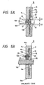
- Fig.5A is a sectional view taken along a line 2-2 in Fig.1 from an arrow direction in Fig.1 for showing an operating state in which the optical fiber 100 is removed
- Fig.5B is a longitudinal sectional view for showing the operating state shown in Fig.5A.
- the first slot 27 is flexed and pushed wide in an outward direction.
- the four lock claws 26 of the leaf spring 12 communicated with the first recess groove 27 are flexed concurrently by this flexing force, bite into the covering section 100b of the optical fiber 100, or each of the extremity ends 35 of the lock claws 26 forcedly contacted and held is widened and released (t1 and t2 in the figure).
- the flange 13b is abutted against the right wall in the space 23 and stopped there.
- a thickness width of the case 11 in an inserting direction and a pulling-out direction of the optical fiber 100 caused by a laser diode arranged on an axial extending line of the core 100a of the optical fiber 100 attached to and fixed to the device 10, its terminal and a circuit board or the like can be made thin due to the fact that a thickness of the sleeve 52 by itself and a thickness of the case 11 for use in fixing the sleeve 52 as found in the prior art can be eliminated.
- Fig.6 is a front elevational view for showing a schematic configuration of an optical fiber fixing device 40 of an optical communication module.
- Fig.7 is a sectional view taken along a line 7-7 of the optical fiber fixing device 40 as viewed from its arrow direction.
- Fig.8 is a sectional view taken along a line 8-8 of the optical fiber fixing device 40 in Fig.6 as viewed from its arrow direction.
- Figs.9A to 9C are views for showing states in which the optical fiber is inserted into the optical fiber fixing device 40 and locked there, wherein Fig.9A is a front elevational view, Fig.9B is a longitudinal sectional view and Fig.9C is a cross sectional view,respectively.
- Figs.10A to 10C are views for showing the states in which the locked state is released in the optical fiber fixing device 40 having the optical fiber inserted therein, wherein Fig.10A is a front elevational view, Fig.10B is a longitudinal sectional view and Fig.10C is a cross sectional view, respectively.
- the optical fiber fixing device 40 is provided with a substantially rectangular case 41 made of metal having a relative thin thickness or resin having a high rigidity, and the case 41 has a cavity 41a in it.
- This case 41 is made such that a flat wide front wall 44 is arranged at an operator's side as viewed in Fig.6 and then the rear wall 45 (the right side in Fig.7) is arranged at the rear surface thereof in opposition to the front wall 44.
- first side wall 46a and a second side wall 46b extending in an upward or downward direction of the four surfaces connecting the parallel front wall 44 and rear wall 45, respectively.
- An insertion hole 47 for the optical fiber is punched in a circular shape and formed at the central part of the front wall 44. Further, the central part of the front wall 44 is provided with a smaller rectangular fixing hole 48 than the insertion hole 47 in such a way that it may be positioned between the insertion hole 47 and the first side wall 46a.
- a protrusion (abutting section) 43 having a substantially angular-shaped sectional shape projecting from the inner wall of the rear wall 45 toward the inner wall of the front wall 44 is integrally attached to and fixed to its inner wall of the cavity 41a of the case 41.
- a substantially circular-shaped opening 52 formed at the central part of the rear wall 45 is formed at the rear wall 45 in opposition to the insertion hole 47 of the front wall 44.
- the leaf spring 42 is formed such that a metallic plate member made of stainless steel or phosphorous bronze is formed to have a certain resiliency and the leaf spring is comprised of a pair of base plate pieces 42a, 42b; a substantially circular through-pass hole 55 punched and formed at the central part of each of the base plate pieces 42a, 42b; a wide width part 42c connecting one end of each of the base plate pieces 42a, 42b to each other and having a wider width than those of the remaining portions; a pair of bending sections 42d, 42e formed by bending the other ends of the base plate pieces; and operating sections 42f, 42g arranged at the extremity ends of these bent sections 42d, 42e.
- the leaf spring 42 has, between a pair of bent sections 42d, 42e, a first slot 57 communicated with the through-pass hole 55 and recessed to be formed in a linear shape; and a second slot 58 recessed to be formed in a linear shape to reach the through-pass hole 55 from below.
- the leaf spring 42 is easily flexed under an arrangement of the first and second slots 57, 58.
- lock claws 56 are bent and formed on the base plate piece 42a from the edge part of the through-pass hole 55 of the base plate piece 42a.
- the extremity end 65 of the lock claw 56 is formed by a crushing work in such a way that a sectional surface in a plate thickness direction may show an acute angle.
- such a leaf spring 42 as described above is stored in the cavity 41a such that the lock claw 56 is arranged in the insertion hole 47 of the front wall 44 and the opening 52 of the rear wall 45, or the first slot 57 is placed at the first side wall 46a of the case 41 and the second slot 58 is placed at the second side wall 46b of the case 41.
- the operating sections 42f, 42g acting as extremity ends of the bent sections 42d, 42e of the leaf spring 42 are projected out of the fixing hole 48 of the case 41 in an outward direction. Further, the wide width part 42c is inserted into the lower groove in the cavity 41a, attached and fixed there.
- the part of the first recess groove 57 of the bent sections 42d, 42e of the leaf spring 42 is oppositely faced against the protrusion 43 of the rear wall 45 acting as the abutted part.
- the lock claws 56 of the leaf spring 42 stored in the cavity 41a of the case 41 may accept a force in which their extremity ends 65 are bent in an inserting direction of the optical fiber 100, resulting in that the extremity ends 65 are pushed out toward an inserting direction of the optical fiber 100 to cause a clearance between each of the extremity ends 65 to be widened.
- the extremity ends 65 slide on the outer circumferential surface of the covering part 100b of the optical fiber 100 to cause the optical fiber 100 to be smoothly inserted into the case 41.
- one end of the optical fiber 100 is fitted at a predetermined position (not shown) and insertion of the optical fiber 100 into the case 41 is terminated and the covering part 100b of the optical fiber 100 is resiliently pressed by the extremity ends 65 of the lock claws 56.
- the optical fiber 100 is held by the leaf spring 42 and positively attached and fixed in the case 41.
- the optical fiber 100 is fixed to the optical fiber fixing device 40 to cause the laser beam incident to one end of the core 100a of the optical fiber (the left side as viewed in Fig.9B) from the laser diode (not shown) to be transmitted within the core 100a and outputted at the other end (the right side as viewed in the figure).
- This pushing-in operation causes the entire leaf spring 42 to be flexed around a fulcrum point of the groove part of the case 41 fitted to the wide width part 42c and further the bent sections 42d, 42e accepting the pushing force to be moved in the cavity 41a from the front wall 44 of the case 41 to the rear wall 45 of it.
- the part of the first slot 57 at the bent sections 42d, 42e strikes against a protrusion 43 projected into the cavity 41a and then the bent sections 42d, 42e are moved in such a direction as one in which the width of the first slot 57 is largely widened.
- the four lock claws 56 of the leaf spring 42 communicated with the bent sections 42d, 42e are flexed concurrently, bite into the covering part 100b of the optical fiber 100 or each of the extremity ends 65 of the press fitted and held lock claws 56 is widened and released (t3 and t4 in Fig.10C), respectively. Then, a part of the bent sections 42d, 42e strikes against the inner wall of the rear wall 45 and stops there.
- the optical fiber fixing device 40 is constituted such that the protrusion 43 for releasing the lock claws 56 is integrally formed with the rear wall 45 of the case 41, the leaf spring 42 is bent toward the abutting part acting as the protrusion 43 at the time of releasing operation to expand the first slot 57, thereby it can be released without arranging another releasing member (an operating button for depressing operation) and since there is no wall for preventing another member (the pushing button) from being dropped, it is possible to make its thickness thinner.
- each of concave sections corresponding to the shape of each of the base plate pieces 42a, 42b is formed, respectively, each of the concave sections is made as a slant surface in such a way that the width of the first slot 57 is widened in response to the motion of the leaf spring 42 at each of the concave sections, a part of each of the base plate pieces 42a, 42b is engaged with each of the concave sections so as to widen the first recess groove 57.
- the optical fiber fixing device is constructed such that the front wall of the case provided with a cavity is formed with an insertion hole, a movable leaf spring is stored in the cavity, the leaf spring has a through-pass hole and a slot opening into the through-pass hole, the circumferential edge of the through-pass hole is formed with a plurality of lock claws, an optical fiber is inserted through the insertion hole and the through-pass hole of the leaf spring, the claws are engaged with the optical fiber, an operating part arranged to deform the recess groove is operated to release an engagement between the optical fiber and the lock claws, thereby when the optical fiber is inserted into the case, it can be smoothly inserted into the case while being abutted against the lock claws having resiliency, its biting and holding of the optical fiber with the lock claws can be carried out and when the optical fiber is released from the case, the operating part is pressed and operated against the slot spaced apart from the lock claws, resulting in that the root part of each of the lock claws in the
- the slot is comprised of a first slot and a second slot, these first and second slots are arranged oppositely from each other with the through-pass hole being held therebetween, thereby the lock claws of the leaf spring spaced apart from the operating part can be widely flexed at their root portions even with a small amount of flexing caused by depressing the operating part and then the insertion and the pulling-out of the optical fiber in respect to the case can be carried out surely.
- the leaf spring is pressed against the abutting section to widen the recess groove, thereby it is not necessary to arrange another member for releasing the fixed state of the optical fiber, it is not required to arrange a configuration for preventing another member from being dropped, it is further possible to make a sufficient thin thickness of the member and then a thinner and smaller-sized configuration can be attained.
- the operating part is comprised of a system in which a part of the leaf spring is fed out of the case, the number of component parts can be reduced and its cost can be reduced.
Landscapes
- Physics & Mathematics (AREA)
- General Physics & Mathematics (AREA)
- Optics & Photonics (AREA)
- Optical Couplings Of Light Guides (AREA)
- Mounting And Adjusting Of Optical Elements (AREA)
- Light Guides In General And Applications Therefor (AREA)
Claims (5)
- Befestigungsvorrichtung für einen Lichtwellenleiter, enthaltend
eine Blattfeder (12), die mit einem Durchgangsloch (25) und mit einer Vielzahl von Verriegelungsklauen (26) versehen ist, die an einem Umfangsrand des Durchgangslochs angeordnet sind, wobei die Blattfeder innerhalb eines Hohlraumes (11a) angeordnet ist. welcher mit einem an einer Vorderwand (14) eines Gehäuses (11) gebildeten Einführloch (17) verbunden ist, und wobei ein Lichtwellenleiter (100) in und durch das Durchgangsloch einführbar ist und die Verriegelungsklauen mit dem Lichtwellenleiter in Eingriff bringbar sind;
welche Blattfeder mit einem Schlitz (27) versehen ist, der sich in das Durchgangsloch öffnet, und welche Blattfeder in einer zu einer Einführrichtung des Lichtwellenleiters senkrechten Ebene angeordnet ist; dadurch gekennzeichnet, dass
die Befestigungsvorrichtung für einen Lichtwellenleiter ferner einen Anstoßteil enthält, der dem Schlitz gegenüberliegend auf diesen zu weist. sowie einen Betätigungsteil (13a, 42f, 42g), der so betätigbar ist, dass er veranlasst, dass der Anstoßteil an dem Schlitz anstößt; und wobei
die Seitenwände des Schlitzes in Einführrichtung des Lichtwellenleiters verformbar sind, und wobei der Schlitz so ausgelegt ist, dass sich das Durchgangsloch erweitert, um den Eingriff zwischen dem Lichtwellenleiter und den Verriegelungsklauen zu lösen, wenn die Seitenwände des Schlitzes in einem verformten Zustand sind. - Befestigungsvorrichtung für einen Lichtwellenleiter nach Anspruch 1, bei welcher der Schlitz aus einem ersten Schlitz (27) und einem zweiten Schlitz (28) besteht und der erste und der zweite Schlitz einander entgegengesetzt angeordnet sind, wobei das Durchgangsloch zwischen ihnen gehalten ist.
- Befestigungsvorrichtung für einen Lichtwellenleiter nach Anspruch 1. bei welcher der Anstoßteil innerhalb des Hohlraumes angeordnet ist und die Blattfeder an dem Anstoßteil anstößt, um dadurch den Schlitz zu erweitern.
- Befestigungsvorrichtung für einen Lichtwellenleiter nach einem der Ansprüche 1 bis 3, bei welcher der Betätigungsteil durch Vorschieben eines Teiles der Blattfeder aus dem Gehäuse hergestellt wird.
- Befestigungsvorrichtung für einen Lichtwellenleiter nach einem der Ansprüche 1 bis 3, bei welcher der Betätigungsteil aus einem Betätigungsknopf besteht, der an dem Gehäuse beweglich angebracht ist.
Applications Claiming Priority (4)
| Application Number | Priority Date | Filing Date | Title |
|---|---|---|---|
| JP22274798 | 1998-08-06 | ||
| JP22274798 | 1998-08-06 | ||
| JP11303499A JP3715825B2 (ja) | 1998-08-06 | 1999-04-21 | 光ファイバ固定装置 |
| JP11303499 | 1999-04-21 |
Publications (3)
| Publication Number | Publication Date |
|---|---|
| EP0978742A2 EP0978742A2 (de) | 2000-02-09 |
| EP0978742A3 EP0978742A3 (de) | 2001-10-17 |
| EP0978742B1 true EP0978742B1 (de) | 2003-03-12 |
Family
ID=26452061
Family Applications (1)
| Application Number | Title | Priority Date | Filing Date |
|---|---|---|---|
| EP99305630A Expired - Lifetime EP0978742B1 (de) | 1998-08-06 | 1999-07-15 | Besfestigungsvorrichtung für eine optische Faser zur Kopplung mit einem optischen Kommunikationsmodul |
Country Status (4)
| Country | Link |
|---|---|
| US (1) | US6167184A (de) |
| EP (1) | EP0978742B1 (de) |
| JP (1) | JP3715825B2 (de) |
| DE (1) | DE69905813T2 (de) |
Families Citing this family (8)
| Publication number | Priority date | Publication date | Assignee | Title |
|---|---|---|---|---|
| CN1284990C (zh) * | 2001-04-03 | 2006-11-15 | 莫列斯公司 | 安装光纤的装置和方法 |
| US20040190851A1 (en) * | 2003-03-31 | 2004-09-30 | Garner Sean M. | Two-dimensional optical element arrays |
| JP4523874B2 (ja) * | 2005-06-01 | 2010-08-11 | ホシデン株式会社 | 光コネクタ |
| JP2007149316A (ja) * | 2005-11-02 | 2007-06-14 | Alps Electric Co Ltd | 薄膜磁気ヘッド素子の検査方法及び検査用保持治具 |
| DE102006008091B4 (de) * | 2006-02-20 | 2010-01-14 | Phoenix Contact Gmbh & Co. Kg | Anschlussklemme für mindestens einen Lichtwellenleiter |
| IE20080831A1 (en) * | 2007-10-12 | 2009-06-24 | Firecomms Ltd | An optical fibre connector |
| FR3128766B1 (fr) * | 2021-10-29 | 2024-01-05 | Valeo Vision | Dispositif de fixation d’un guide de lumière pour véhicule |
| CN114172989B (zh) * | 2022-02-11 | 2022-06-17 | 荣耀终端有限公司 | 电子设备及电子设备的组装方法 |
Family Cites Families (9)
| Publication number | Priority date | Publication date | Assignee | Title |
|---|---|---|---|---|
| DE2907705C2 (de) * | 1979-02-28 | 1984-10-11 | Schaltbau GmbH, 8000 München | Vorrichtung zum Andrücken eines Lichtwellenleiters an ein photoelektrisches Bauelement |
| US4342496A (en) * | 1980-05-22 | 1982-08-03 | Bunker Ramo Corporation | Contact assembly incorporating retaining means |
| EP0248902B1 (de) * | 1985-12-26 | 1993-04-07 | The Whitaker Corporation | Verbindungsstück mit optischen fasern |
| ES2050174T3 (es) * | 1988-03-30 | 1994-05-16 | Omron Tateisi Electronics Co | Estructura para acoplar fibras opticas a un conmutador fotoelectrico. |
| JP3014590B2 (ja) * | 1993-12-14 | 2000-02-28 | 古河電気工業株式会社 | 光コネクタの端面加工装置 |
| ATE187256T1 (de) * | 1994-07-21 | 1999-12-15 | Rxs Schrumpftech Garnituren | Abfangsvorrichtung für optische kabel |
| JP3209044B2 (ja) * | 1995-06-13 | 2001-09-17 | 住友電装株式会社 | 光コネクタ及び光コネクタへの光ファイバの固定方法 |
| JP3624360B2 (ja) * | 1996-04-24 | 2005-03-02 | 富士通株式会社 | 光モジュール |
| DE19626080B4 (de) * | 1996-06-28 | 2005-12-29 | The Whitaker Corp., Wilmington | Anordnung zur Befestigung eines Lichtwellenleiters |
-
1999
- 1999-04-21 JP JP11303499A patent/JP3715825B2/ja not_active Expired - Fee Related
- 1999-07-15 DE DE69905813T patent/DE69905813T2/de not_active Expired - Fee Related
- 1999-07-15 EP EP99305630A patent/EP0978742B1/de not_active Expired - Lifetime
- 1999-08-03 US US09/365,997 patent/US6167184A/en not_active Expired - Fee Related
Also Published As
| Publication number | Publication date |
|---|---|
| EP0978742A2 (de) | 2000-02-09 |
| JP3715825B2 (ja) | 2005-11-16 |
| DE69905813D1 (de) | 2003-04-17 |
| US6167184A (en) | 2000-12-26 |
| DE69905813T2 (de) | 2003-12-11 |
| EP0978742A3 (de) | 2001-10-17 |
| JP2000111744A (ja) | 2000-04-21 |
Similar Documents
| Publication | Publication Date | Title |
|---|---|---|
| EP1073923B1 (de) | Steckergehäuse mit schnappverbindung für einen faseroptischen stecker | |
| US7413351B2 (en) | Optical connection apparatus which has a shutter and which can be designed to be small in size | |
| US6776645B2 (en) | Latch and release system for a connector | |
| EP0685750A1 (de) | Stecker zum Verbinden eines faseroptischen Kabels | |
| EP1477834B1 (de) | Optisches Modul mit der Fähigkeit zum vereinfachten Lösen der Verrastung mit dem das Modul aufnehmenden Gehäuse | |
| US20200284998A1 (en) | Mini duplex connector with push-pull polarity mechanism and carrier | |
| EP1278084B1 (de) | Optischer Verbinder | |
| US8118495B2 (en) | Method of assembling an optical connector and an optical connector | |
| US7422376B2 (en) | Self-contained fiber optic connector module | |
| JP4766619B2 (ja) | 光アダプタ | |
| EP1168018A2 (de) | Faseroptischer Verbinder | |
| US6167184A (en) | Optical fiber fixing device for optically coupling optical fiber with optical communication module | |
| WO2019146223A1 (ja) | 光接続構造、光コネクタ部品、及びハウジング | |
| US20040091214A1 (en) | Fiber Optical Connector | |
| US20060169856A1 (en) | Fiber optic adapter including removable mount | |
| US6527451B2 (en) | Optical connector device for holding optical fiber cord | |
| JP2001051155A (ja) | 光コネクタ | |
| US5926597A (en) | Connector for optical fiber | |
| JP5396413B2 (ja) | 光コネクタ及び治具 | |
| CN113660881B (zh) | 带扣 | |
| JPH0778568B2 (ja) | 光コネクタプラグ | |
| JP2543360Y2 (ja) | 受容体およびコネクタ | |
| JPH10239560A (ja) | 光コネクタ接続工具 | |
| HK1070748B (en) | Optical module capable of facilitating release from locking state with cage which accommodates optical module |
Legal Events
| Date | Code | Title | Description |
|---|---|---|---|
| PUAI | Public reference made under article 153(3) epc to a published international application that has entered the european phase |
Free format text: ORIGINAL CODE: 0009012 |
|
| AK | Designated contracting states |
Kind code of ref document: A2 Designated state(s): AT BE CH CY DE DK ES FI FR GB GR IE IT LI LU MC NL PT SE Kind code of ref document: A2 Designated state(s): DE GB |
|
| AX | Request for extension of the european patent |
Free format text: AL;LT;LV;MK;RO;SI |
|
| PUAL | Search report despatched |
Free format text: ORIGINAL CODE: 0009013 |
|
| AK | Designated contracting states |
Kind code of ref document: A3 Designated state(s): AT BE CH CY DE DK ES FI FR GB GR IE IT LI LU MC NL PT SE |
|
| AX | Request for extension of the european patent |
Free format text: AL;LT;LV;MK;RO;SI |
|
| RIC1 | Information provided on ipc code assigned before grant |
Free format text: 7G 02B 6/42 A, 7G 02B 6/36 B, 7G 02B 6/38 B |
|
| 17P | Request for examination filed |
Effective date: 20011018 |
|
| 17Q | First examination report despatched |
Effective date: 20020128 |
|
| AKX | Designation fees paid |
Free format text: DE GB |
|
| GRAH | Despatch of communication of intention to grant a patent |
Free format text: ORIGINAL CODE: EPIDOS IGRA |
|
| GRAH | Despatch of communication of intention to grant a patent |
Free format text: ORIGINAL CODE: EPIDOS IGRA |
|
| GRAA | (expected) grant |
Free format text: ORIGINAL CODE: 0009210 |
|
| AK | Designated contracting states |
Designated state(s): DE GB |
|
| REG | Reference to a national code |
Ref country code: GB Ref legal event code: FG4D |
|
| REF | Corresponds to: |
Ref document number: 69905813 Country of ref document: DE Date of ref document: 20030417 Kind code of ref document: P |
|
| PLBE | No opposition filed within time limit |
Free format text: ORIGINAL CODE: 0009261 |
|
| STAA | Information on the status of an ep patent application or granted ep patent |
Free format text: STATUS: NO OPPOSITION FILED WITHIN TIME LIMIT |
|
| 26N | No opposition filed |
Effective date: 20031215 |
|
| PGFP | Annual fee paid to national office [announced via postgrant information from national office to epo] |
Ref country code: DE Payment date: 20080919 Year of fee payment: 10 |
|
| PGFP | Annual fee paid to national office [announced via postgrant information from national office to epo] |
Ref country code: GB Payment date: 20080530 Year of fee payment: 10 |
|
| GBPC | Gb: european patent ceased through non-payment of renewal fee |
Effective date: 20090715 |
|
| PG25 | Lapsed in a contracting state [announced via postgrant information from national office to epo] |
Ref country code: GB Free format text: LAPSE BECAUSE OF NON-PAYMENT OF DUE FEES Effective date: 20090715 |
|
| PG25 | Lapsed in a contracting state [announced via postgrant information from national office to epo] |
Ref country code: DE Free format text: LAPSE BECAUSE OF NON-PAYMENT OF DUE FEES Effective date: 20100202 |