EP0248902B1 - Verbindungsstück mit optischen fasern - Google Patents
Verbindungsstück mit optischen fasern Download PDFInfo
- Publication number
- EP0248902B1 EP0248902B1 EP87902880A EP87902880A EP0248902B1 EP 0248902 B1 EP0248902 B1 EP 0248902B1 EP 87902880 A EP87902880 A EP 87902880A EP 87902880 A EP87902880 A EP 87902880A EP 0248902 B1 EP0248902 B1 EP 0248902B1
- Authority
- EP
- European Patent Office
- Prior art keywords
- optical fiber
- connector
- bore
- housing
- slot
- Prior art date
- Legal status (The legal status is an assumption and is not a legal conclusion. Google has not performed a legal analysis and makes no representation as to the accuracy of the status listed.)
- Expired - Lifetime
Links
Images


Classifications
-
- G—PHYSICS
- G02—OPTICS
- G02B—OPTICAL ELEMENTS, SYSTEMS OR APPARATUS
- G02B6/00—Light guides; Structural details of arrangements comprising light guides and other optical elements, e.g. couplings
- G02B6/24—Coupling light guides
- G02B6/36—Mechanical coupling means
- G02B6/38—Mechanical coupling means having fibre to fibre mating means
- G02B6/3801—Permanent connections, i.e. wherein fibres are kept aligned by mechanical means
-
- G—PHYSICS
- G02—OPTICS
- G02B—OPTICAL ELEMENTS, SYSTEMS OR APPARATUS
- G02B6/00—Light guides; Structural details of arrangements comprising light guides and other optical elements, e.g. couplings
- G02B6/24—Coupling light guides
- G02B6/36—Mechanical coupling means
- G02B6/38—Mechanical coupling means having fibre to fibre mating means
- G02B6/3807—Dismountable connectors, i.e. comprising plugs
- G02B6/381—Dismountable connectors, i.e. comprising plugs of the ferrule type, e.g. fibre ends embedded in ferrules, connecting a pair of fibres
- G02B6/3817—Dismountable connectors, i.e. comprising plugs of the ferrule type, e.g. fibre ends embedded in ferrules, connecting a pair of fibres containing optical and electrical conductors
-
- G—PHYSICS
- G02—OPTICS
- G02B—OPTICAL ELEMENTS, SYSTEMS OR APPARATUS
- G02B6/00—Light guides; Structural details of arrangements comprising light guides and other optical elements, e.g. couplings
- G02B6/24—Coupling light guides
- G02B6/36—Mechanical coupling means
- G02B6/38—Mechanical coupling means having fibre to fibre mating means
- G02B6/3807—Dismountable connectors, i.e. comprising plugs
- G02B6/3887—Anchoring optical cables to connector housings, e.g. strain relief features
- G02B6/3888—Protection from over-extension or over-compression
-
- G—PHYSICS
- G02—OPTICS
- G02B—OPTICAL ELEMENTS, SYSTEMS OR APPARATUS
- G02B6/00—Light guides; Structural details of arrangements comprising light guides and other optical elements, e.g. couplings
- G02B6/24—Coupling light guides
- G02B6/42—Coupling light guides with opto-electronic elements
- G02B6/4201—Packages, e.g. shape, construction, internal or external details
- G02B6/4246—Bidirectionally operating package structures
-
- G—PHYSICS
- G02—OPTICS
- G02B—OPTICAL ELEMENTS, SYSTEMS OR APPARATUS
- G02B6/00—Light guides; Structural details of arrangements comprising light guides and other optical elements, e.g. couplings
- G02B6/24—Coupling light guides
- G02B6/42—Coupling light guides with opto-electronic elements
- G02B6/4292—Coupling light guides with opto-electronic elements the light guide being disconnectable from the opto-electronic element, e.g. mutually self aligning arrangements
-
- H—ELECTRICITY
- H01—ELECTRIC ELEMENTS
- H01R—ELECTRICALLY-CONDUCTIVE CONNECTIONS; STRUCTURAL ASSOCIATIONS OF A PLURALITY OF MUTUALLY-INSULATED ELECTRICAL CONNECTING ELEMENTS; COUPLING DEVICES; CURRENT COLLECTORS
- H01R4/00—Electrically-conductive connections between two or more conductive members in direct contact, i.e. touching one another; Means for effecting or maintaining such contact; Electrically-conductive connections having two or more spaced connecting locations for conductors and using contact members penetrating insulation
- H01R4/24—Connections using contact members penetrating or cutting insulation or cable strands
- H01R4/2416—Connections using contact members penetrating or cutting insulation or cable strands the contact members having insulation-cutting edges, e.g. of tuning fork type
- H01R4/2445—Connections using contact members penetrating or cutting insulation or cable strands the contact members having insulation-cutting edges, e.g. of tuning fork type the contact members having additional means acting on the insulation or the wire, e.g. additional insulation penetrating means, strain relief means or wire cutting knives
- H01R4/245—Connections using contact members penetrating or cutting insulation or cable strands the contact members having insulation-cutting edges, e.g. of tuning fork type the contact members having additional means acting on the insulation or the wire, e.g. additional insulation penetrating means, strain relief means or wire cutting knives the additional means having two or more slotted flat portions
- H01R4/2454—Connections using contact members penetrating or cutting insulation or cable strands the contact members having insulation-cutting edges, e.g. of tuning fork type the contact members having additional means acting on the insulation or the wire, e.g. additional insulation penetrating means, strain relief means or wire cutting knives the additional means having two or more slotted flat portions forming a U-shape with slotted branches
Definitions
- This invention is related to an optical fiber connector which is used for connecting optical fibers for transmitting light signals between photo transmitters and receivers.
- the connector is also used for connecting electrical wires for transmitting power to another connector.
- Optical fiber cables used for signal transmission are composed of a linear core formed of optical glass or plastic, and a jacket made of a resin such as urethane, polyethylene, or vinyl covering the outer surface of the glass or plastic core. Such cables are used in various fields such as optical communication.
- the photo signal is transferred by disposing the end portion of the optical fiber to the transmitter or receiver for receiving light signals to the end of another optical fiber to which it is connected and the signal is transferred between the ends of these optical fibers.
- various types of optical connectors have been disclosed.
- the connector disclosed in Unexamined Japanese patent application No. 58-174916 the end portion of an optical fiber cable which is inserted inside the connector housing is clamped by a fastening member which is press-fitted between the connector housing and the optical fiber cable, and thus the optical fiber cable is firmly retained in the connector housing.
- the fastening member retains the end portion of the optical fiber cable inside the connector housing by clamping, and a firm fixation of the optical fiber cable is created by the clamping force.
- the object of this invention is to provide a connector that does not compress the fiber optic core of an optical fiber cable, but firmly and securely retains the end portion of the optical fiber cable in the connector, and further, to provide a connector with a simplified structure in which the optical fiber cable is easily and firmly retained in position in the connector with no loss of light transmission of the fiber optic core.
- the present invention consists in a connector for connection to an optical fiber cable having an optical fiber core and an outer jacket, the connector comprising a housing having a bore for receiving an end of the optical fiber cable, a slot in the housing communicating with the bore, a retaining member in the form of a plate for retaining the optical cable in the bore, having a slot therein having edges for engagement with the optical cable, the retaining member being constructed to be pressed into the housing slot to extend partly into the bore so that the edges of the slot in the retaining member penetrate the outer jacket of the cable, securing means being provided on the retaining member for securing it in the housing; characterized in that said securing means are resilient projection means which extend from said plate outwardly of the plane thereof, and which move parallel to the axis of the bore when plate is being received in the housing slot.
- JP-A-62-17772 discloses an optical fiber connector according to the preamble of claim 1.
- Patent Abstracts of Japan, Vol.8, No. 14 (P-249) [1451] 21st January 1984 and JP-A-174916 also disclose an optical fiber connector in which an optical fiber cable is positioned in a bore in a housing by means of a retaining member pressed into a slot in the housing.
- US-A-4 533 199 discloses, for securing a U-shaped contact element in a slot in a housing, an anvil member on a cover of the housing, the anvil member engaging the contact element.
- EP-A-0 092 338 discloses a spring latching member for retaining a fiber optic connector in a housing, the latching member having mounting legs provided with arcuate projections for frictional engagement in holes in a printed circuit board.
- US-A-4 327 964 discloses a retainer which is inserted into a slot in a housing which slot extends transversely of the axis of an optical fiber ferrule in a bore in the housing.
- the retainer retains the ferrule in the bore.
- EP-A-0 092 338 and Research Disclosure No. 218, June 1982, P196 abstract No. 21822, Havant, Hampshire, GB "Optical Connector” disclose the incorporation of a photoelectronic member into a bore of an optical fiber connector housing.
- Figure 1 is a perspective view showing the connector assembly of the optical fiber connector which is composed of a plug connector 1 wherein an end portion of an optical fiber cable 5 is secured, and a receptacle connector 3 wherein a photoelectronic element 6 is secured.
- the plug connector 1 is an optical fiber connector according to an embodiment of this invention and is composed of a connector body 10 and a retaining plate 20. An end portion of an optical fiber cable 5 is inserted into the connector body 10 and is firmly retained therein by the retaining plate 20.
- a fiber optic core 5b is inserted in connector body 10 to the end face of a cylindrical portion 12 of the connector body 10.
- Cylindrical portion 12 acts as a ferrule for the connector.
- the receptacle connector 3 has a cylindrical bore 32 which extends therethrough from the back to the front thereof, and at the front portion thereof, connector 3 has latching arms 31 which engage with engaging projections 11 of the connector body 10.
- a photoelectronic element 6 is secured in the rear end of cylindrical bore 32. This photoelectronic element 6, such as a light emitting diode generates light signals to the optical fiber core. Photoelectronic element 6 can also be a photodetector.
- the cylindrical portion 12 is inserted into the cylindrical bore 32, latching arms 31 engage projections 11 and accordingly, the end face of the fiber optic core 5b is brought adjacent to and opposite to the photoelectronic element 6.
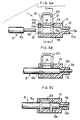
- Figure 2 shows details of the above-mentioned plug connector 1
- Figures 3A to 3C show a method of mounting the optical fiber cable 5 in the plug connector 1.
- Figures 4A to 4C show a method of mounting the optical fiber cable 5 corresponding to Figures 3A and 3G.
- the connector body 10 has a bore 13 extending from the rear end face 10a to the front face 10b of cylindrical portion 12. Bore 13 includes a rear section 13a having a diameter slightly larger than the outer diameter of the jacket of the optical fiber cable 5, and a front section 13b having a diameter slightly larger than the diameter of the fiber optic core 5b. Furthermore, the connector body 10 has an aperture 14 formed from an upper face 10c and in communication with the section 13a. At the back and front of this aperture 14, a pair of vertically extending retaining plate insertion slots 15 are formed.
- the retaining plate 20 is metal formed into a U-shape and includes legs 21, which have U-shaped slots 22. Further, outwardly-directed resilient projections 23 are formed in legs 21.
- a retaining plate 20 is removed from a carrier 25, as shown in Figure 4A.
- the legs 21 of retaining plate 20 are inserted into the plate insertion slots 15, such that the lower ends of both legs 21 do not reach section 13a, with the result that the retaining plate is retained therein by the engagement between the resilient projections 23 and the walls of plate insertion slots 15.
- the optical fiber cable 5 having a partly exposed portion of the core 5b at the end portion thereof is inserted into bore 13.
- the end portion of jacket 5a is inserted inside section 13a, and the exposed core 5b is inserted into the front section 13b as shown in Figure 3B.
- the core 5b is disposed in section 13b and projects slightly forward from the front end face 10b.
- the retaining plate 20 is then pushed down as shown in Figures 3C and 4C. Since retaining plate 20 is made of thin sheet metal, the edges of U-shaped slots 22 are pressed into the jacket 5a of the optical fiber cable 5. At this stage, the projections 23 of the retaining plate 20 dig into the walls of slots 15 and is retained therein thereby securing retaining plate 20 in position in connector body 10 with the edges of U-shaped slots 22 pressed into or penetrating the jacket 5a which secures cable 5 in position in bore 13 of connector body 10.
- the retaining plate 20 firmly retains optical fiber cable 5 in the connector body 10 by the edges of U-shaped slots 22 pressing into or penetrating the jacket 5.
- the retaining plate 20 performs no clamping onto core 5b, the problem of loss of transmission of the light signal by compressing the core does not arise, and a firm retention of the optical fiber cable 5 in the connector is effected.
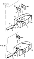
- the optical connector 6 shown in Figure 5 is an example of employing two retaining plates 60 instead of employing the folded type retaining plate 20 in the case mentioned above.
- the same type of connector body 10 as shown in Figures 1 to 4 is used, and is constructed so that each retaining plate 60 is inserted into the respective plate insertion slot 15 to firmly retain the optical fiber cable 5 in the body 10.
- Figure 6 shows only one of the above-mentioned retaining plates 60 being used so that in optical fiber connector 7, only one plate insertion slot 71 is formed in the body 70.
- the optical fiber cable 5, when inserted in bore 13, is firmly retained in the body 70 by using a single retaining plate 60.
Landscapes
- Physics & Mathematics (AREA)
- General Physics & Mathematics (AREA)
- Optics & Photonics (AREA)
- Optical Couplings Of Light Guides (AREA)
- Mechanical Coupling Of Light Guides (AREA)
Claims (4)
- Verbinder (1, 7) zum Verbinden mit einem optischen Faserkabel (5), das einen optischen Faserkern (5b) und einen äußeren Mantel (5a) hat, wobei der Verbinder (1, 7) ein Gehäuse (10, 70) aufweist, das eine Bohrung (13) zur Aufnahme eines Endes des optischen Faserkabels (5) sowie einen Schlitz (14, 15, 71) in dem Gehäuse (10, 70) hat, der mit der Bohrung (13) in Verbindung steht, wobei ein Halteglied (20, 60) in der Form einer Platte (21, 60) zum Halten des optischen Kabeis in der Bohrung (13) vorgesehen ist, wobei die Platte einen Schlitz (22, 61) mit Kanten zum Eingriff mit dem optischen Kabel (5) hat, wobei das Halteglied (20, 60) so konstruiert ist, daβ es in den Gehäuseschlitz (14, 15, 71) eingepresst werden kann, um sich teilweise in die Bohrung (13) zu erstrecken, so daß die Kanten des Schlitzes (22, 61) in dem Halteglied (20, 60) den äußeren Mantel (5a) des Kabels (5) durchdringen, wobei an dem Halteglied (20, 60) Sicherungsmittel für dessen Sicherung in dem Gehäuse (10, 70) vorgesehen sind, dadurch gekennzeichnet, daß die Sicherungsmittel nachgiebige Vorsprünge (23) sind, die sich von der Platte (21, 60) gegenüber deren Ebene nach außen erstrecken und die sich parallel zu der Achse der Bohrung (13) bewegen, wenn die Platte (21, 60) in dem Gehäuseschlitz (14, 15, 71) aufgenommen wird.
- Verbinder nach Anspruch 1, dadurch gekennzeichnet, daß das Halteglied (20) parallele Platten (21) aufweist, die durch eine weitere Platte miteinander verbunden sind.
- Verbinder nach Anspruch 1 oder 2, dadurch gekennzeichnet, daß die Bohrung (13) einen Abschnitt (13b) mit vermindertem Durchmesser zur Aufnahme eines freigelegten Endes des Faserkerns (5b) hat.
- Verbinder nach Anspruch 1, 2 oder 3, dadurch gekennzeichnet, daß ein photoelektronisches Element (6) mit der Bohrung (13) ausgerichtet ist zur Ausrichtung mit einem lichtübertragenden Ende eines optischen Kabels (5), das in der Bohrung (13) aufzunehmen ist.
Priority Applications (1)
| Application Number | Priority Date | Filing Date | Title |
|---|---|---|---|
| EP92202572A EP0517346B1 (de) | 1985-12-26 | 1986-12-19 | Faseroptischer Stecker |
Applications Claiming Priority (4)
| Application Number | Priority Date | Filing Date | Title |
|---|---|---|---|
| JP299661/85 | 1985-12-26 | ||
| JP29966185A JPS62159108A (ja) | 1985-12-26 | 1985-12-26 | 光フアイバ用コネクタ |
| JP74099/86 | 1986-03-31 | ||
| JP7409986A JPS62232608A (ja) | 1986-03-31 | 1986-03-31 | 光電複合型コネクタ |
Related Child Applications (1)
| Application Number | Title | Priority Date | Filing Date |
|---|---|---|---|
| EP92202572.1 Division-Into | 1992-08-25 |
Publications (3)
| Publication Number | Publication Date |
|---|---|
| EP0248902A1 EP0248902A1 (de) | 1987-12-16 |
| EP0248902A4 EP0248902A4 (de) | 1990-02-05 |
| EP0248902B1 true EP0248902B1 (de) | 1993-04-07 |
Family
ID=26415237
Family Applications (2)
| Application Number | Title | Priority Date | Filing Date |
|---|---|---|---|
| EP87902880A Expired - Lifetime EP0248902B1 (de) | 1985-12-26 | 1986-12-19 | Verbindungsstück mit optischen fasern |
| EP92202572A Expired - Lifetime EP0517346B1 (de) | 1985-12-26 | 1986-12-19 | Faseroptischer Stecker |
Family Applications After (1)
| Application Number | Title | Priority Date | Filing Date |
|---|---|---|---|
| EP92202572A Expired - Lifetime EP0517346B1 (de) | 1985-12-26 | 1986-12-19 | Faseroptischer Stecker |
Country Status (6)
| Country | Link |
|---|---|
| US (1) | US4986625A (de) |
| EP (2) | EP0248902B1 (de) |
| KR (1) | KR920001121B1 (de) |
| DE (2) | DE3650519T2 (de) |
| ES (1) | ES1005088Y (de) |
| WO (1) | WO1987003969A1 (de) |
Cited By (1)
| Publication number | Priority date | Publication date | Assignee | Title |
|---|---|---|---|---|
| US5835652A (en) * | 1995-10-26 | 1998-11-10 | Molex Incorporated | Optical fiber cable connector |
Families Citing this family (114)
| Publication number | Priority date | Publication date | Assignee | Title |
|---|---|---|---|---|
| US5166995A (en) * | 1984-06-08 | 1992-11-24 | Amp Incorporated | Polarized connector |
| DE3727092C1 (de) * | 1987-08-14 | 1988-11-10 | Wieland Elek Sche Ind Gmbh F | Lichtleiteranschlussklemme |
| KR910005522A (ko) * | 1989-08-11 | 1991-03-30 | 제이 엘.사이칙 | 케이블 커넥터 |
| FR2658956B1 (fr) * | 1990-02-26 | 1994-02-25 | Alcatel Radiotelephone | Dispositif pour fixer un cable coaxial, et le relier a la masse d'une plaque de circuit imprime. |
| ZA937551B (en) * | 1992-10-13 | 1994-05-03 | Utilux Pty Ltd | A planar member for gripping a cable |
| DE4244898C2 (de) * | 1992-11-23 | 1998-04-23 | Grote & Hartmann | Vielpoliger elektrischer Steckverbinder |
| JP2758808B2 (ja) * | 1993-05-28 | 1998-05-28 | 日本電気 株式会社 | 光ファイバコネクタ用フェルール構造 |
| US5732176A (en) * | 1993-06-29 | 1998-03-24 | Savage, Jr.; John M. | Light pipe optical coupling between LED and fiber optics cable |
| US5440658A (en) * | 1993-06-29 | 1995-08-08 | Savage, Jr.; John M. | Modular fiber optic cable assembly |
| US5818995A (en) * | 1993-06-29 | 1998-10-06 | Savage, Jr.; John M. | Lens unit and light pipe assembly |
| US5548676A (en) * | 1993-06-29 | 1996-08-20 | Savage, Jr.; John M. | Light pipe optical coupling between led and fiber optics cable |
| USRE40150E1 (en) | 1994-04-25 | 2008-03-11 | Matsushita Electric Industrial Co., Ltd. | Fiber optic module |
| JP2780640B2 (ja) * | 1994-05-25 | 1998-07-30 | 住友電装株式会社 | 光ファイバーケーブルの接続コネクタ |
| EP0713111A1 (de) * | 1994-11-15 | 1996-05-22 | The Whitaker Corporation | Abgedichteter faseroptischer Mehrfachstecker |
| US6220878B1 (en) | 1995-10-04 | 2001-04-24 | Methode Electronics, Inc. | Optoelectronic module with grounding means |
| US5717533A (en) | 1995-01-13 | 1998-02-10 | Methode Electronics Inc. | Removable optoelectronic module |
| US5546281A (en) | 1995-01-13 | 1996-08-13 | Methode Electronics, Inc. | Removable optoelectronic transceiver module with potting box |
| US6072613A (en) * | 1995-08-21 | 2000-06-06 | Telefonaktiebolaget Lm Ericsson | Opto module |
| SE504811C2 (sv) * | 1995-08-21 | 1997-04-28 | Ericsson Telefon Ab L M | Kopplingsdon samt anordning vid elektrooptisk krets |
| SE504812C2 (sv) * | 1995-08-21 | 1997-04-28 | Ericsson Telefon Ab L M | Optomodul |
| DE19533296C2 (de) * | 1995-09-08 | 1997-09-11 | Siemens Ag | Befestigungsvorrichtung für Lichtwellenleiter |
| KR0184963B1 (ko) * | 1995-10-31 | 1999-05-15 | 유기범 | 다심 광 케이블 접속용 콘넥터 조립체 |
| US5638477A (en) * | 1995-12-22 | 1997-06-10 | Minnesota Mining And Manufacturing Company | Strain relief means for optical fiber splicing member and improved tool for making the splice |
| JP3211700B2 (ja) * | 1997-02-20 | 2001-09-25 | 住友電装株式会社 | 光コネクタ |
| DE19732092C1 (de) * | 1997-07-03 | 1998-12-17 | Phoenix Contact Gmbh & Co | Anschlußklemme für Lichtwellenleiterkabel |
| US6179627B1 (en) | 1998-04-22 | 2001-01-30 | Stratos Lightwave, Inc. | High speed interface converter module |
| US6203333B1 (en) | 1998-04-22 | 2001-03-20 | Stratos Lightwave, Inc. | High speed interface converter module |
| JP2000028866A (ja) * | 1998-07-09 | 2000-01-28 | Alps Electric Co Ltd | 光ファイバ固定装置 |
| JP3715825B2 (ja) * | 1998-08-06 | 2005-11-16 | アルプス電気株式会社 | 光ファイバ固定装置 |
| DE19945173B4 (de) * | 1998-09-22 | 2008-05-15 | The Whitaker Corp., Wilmington | Steckverbinder für zumindest ein Lichtwellenleiter-Kabel |
| EP0989429B1 (de) * | 1998-09-23 | 2002-11-27 | Datasensor S.p.A. | Vorrichtung zur Befestigung von mindestens einer optischen Faser an einem optischen Gerät |
| US6873800B1 (en) | 1999-05-26 | 2005-03-29 | Jds Uniphase Corporation | Hot pluggable optical transceiver in a small form pluggable package |
| US7013088B1 (en) | 1999-05-26 | 2006-03-14 | Jds Uniphase Corporation | Method and apparatus for parallel optical interconnection of fiber optic transmitters, receivers and transceivers |
| US6213651B1 (en) | 1999-05-26 | 2001-04-10 | E20 Communications, Inc. | Method and apparatus for vertical board construction of fiber optic transmitters, receivers and transceivers |
| US6901221B1 (en) | 1999-05-27 | 2005-05-31 | Jds Uniphase Corporation | Method and apparatus for improved optical elements for vertical PCB fiber optic modules |
| US7116912B2 (en) * | 1999-05-27 | 2006-10-03 | Jds Uniphase Corporation | Method and apparatus for pluggable fiber optic modules |
| US20020030872A1 (en) * | 1999-05-27 | 2002-03-14 | Edwin Dair | Method and apparatus for multiboard fiber optic modules and fiber optic module arrays |
| US20040069997A1 (en) * | 1999-05-27 | 2004-04-15 | Edwin Dair | Method and apparatus for multiboard fiber optic modules and fiber optic module arrays |
| US20010030789A1 (en) * | 1999-05-27 | 2001-10-18 | Wenbin Jiang | Method and apparatus for fiber optic modules |
| US20010048793A1 (en) * | 1999-05-27 | 2001-12-06 | Edwin Dair | Method and apparatus for multiboard fiber optic modules and fiber optic module arrays |
| US6952532B2 (en) * | 1999-05-27 | 2005-10-04 | Jds Uniphase Corporation | Method and apparatus for multiboard fiber optic modules and fiber optic module arrays |
| US6632030B2 (en) | 1999-05-27 | 2003-10-14 | E20 Communications, Inc. | Light bending optical block for fiber optic modules |
| US20020033979A1 (en) * | 1999-05-27 | 2002-03-21 | Edwin Dair | Method and apparatus for multiboard fiber optic modules and fiber optic module arrays |
| US7090509B1 (en) | 1999-06-11 | 2006-08-15 | Stratos International, Inc. | Multi-port pluggable transceiver (MPPT) with multiple LC duplex optical receptacles |
| US6325549B1 (en) * | 1999-07-13 | 2001-12-04 | Lucent Technologies Inc | Connectors for plastic optical fiber |
| US6220873B1 (en) | 1999-08-10 | 2001-04-24 | Stratos Lightwave, Inc. | Modified contact traces for interface converter |
| DE19955027A1 (de) * | 1999-11-16 | 2001-05-17 | Delphi Tech Inc | Verbinderteil eines optisch/elektrischen Steckverbinders |
| US6302595B1 (en) | 2000-03-14 | 2001-10-16 | Bivar, Inc. | Optical transmission system |
| US6431763B1 (en) * | 2000-04-13 | 2002-08-13 | Fitel Usa Corp. | Connector for plastic optical fibers |
| USD446770S1 (en) | 2000-09-29 | 2001-08-21 | Hon Hai Precision Ind. Co., Ltd. | Optielectrical connector |
| JP2002131584A (ja) * | 2000-10-20 | 2002-05-09 | Auto Network Gijutsu Kenkyusho:Kk | 光コネクタ装置 |
| US6942395B1 (en) | 2001-01-29 | 2005-09-13 | Jds Uniphase Corporation | Method and apparatus of pull-lever release for fiber optic modules |
| EP1229364B1 (de) * | 2001-02-05 | 2005-01-05 | Tyco Electronics AMP GmbH | Trägergehäuse für einen Lichtwellenleiter |
| NL1017619C2 (nl) * | 2001-03-16 | 2002-10-07 | Koninkl Kpn Nv | Methode voor het in een gebouw aanbrengen van een breedband infrastructuur door middel van optische vezels. |
| US6643225B2 (en) * | 2001-03-21 | 2003-11-04 | Hewlett-Packard Development Company, L.P. | System and method for retaining a first part against a second part |
| US6840680B1 (en) | 2001-04-14 | 2005-01-11 | Jds Uniphase Corporation | Retention and release mechanisms for fiber optic modules |
| US6796715B2 (en) | 2001-04-14 | 2004-09-28 | E20 Communications, Inc. | Fiber optic modules with pull-action de-latching mechanisms |
| US6994478B1 (en) | 2001-04-14 | 2006-02-07 | Jds Uniphase Corporation | Modules having rotatable release and removal lever |
| US6692159B2 (en) | 2001-04-14 | 2004-02-17 | E20 Communications, Inc. | De-latching mechanisms for fiber optic modules |
| US6863448B2 (en) | 2001-04-14 | 2005-03-08 | Jds Uniphase Corporation | Method and apparatus for push button release fiber optic modules |
| US6851867B2 (en) * | 2001-04-14 | 2005-02-08 | Jds Uniphase Corporation | Cam-follower release mechanism for fiber optic modules with side delatching mechanisms |
| TW505223U (en) * | 2001-11-07 | 2002-10-01 | Hon Hai Prec Ind Co Ltd | Optical fiber holding device |
| US7118281B2 (en) | 2002-08-09 | 2006-10-10 | Jds Uniphase Corporation | Retention and release mechanisms for fiber optic modules |
| JP4064784B2 (ja) * | 2002-10-16 | 2008-03-19 | 矢崎総業株式会社 | 光コネクタ |
| JP2005128045A (ja) * | 2003-10-21 | 2005-05-19 | Auto Network Gijutsu Kenkyusho:Kk | 光ケーブル固定部構造 |
| FR2863367A1 (fr) * | 2003-12-05 | 2005-06-10 | Framatome Connectors Int | Element de connecteur de cable optique pourvu de moyens ameliores de blocage de la section d'extremite de cable a raccorder |
| JP4017171B2 (ja) * | 2004-09-28 | 2007-12-05 | 日本航空電子工業株式会社 | クランプ部材 |
| US7660128B2 (en) * | 2004-09-30 | 2010-02-09 | Emcore Corporation | Apparatus for electrical and optical interconnection |
| US7373031B2 (en) * | 2004-09-30 | 2008-05-13 | Intel Corporation | Apparatus for an electro-optical device connection |
| JP4523874B2 (ja) * | 2005-06-01 | 2010-08-11 | ホシデン株式会社 | 光コネクタ |
| EP2363739A3 (de) * | 2006-06-21 | 2011-09-21 | Firecomms Limited | Optischer Stecker |
| DE102006046004A1 (de) * | 2006-09-27 | 2008-04-03 | Tyco Electronics Amp Gmbh | Stecksystem zum Ankoppeln mindestens einer optischen Faser |
| DE102006062279B4 (de) * | 2006-12-22 | 2011-04-07 | Avago Technologies Fiber Ip (Singapore) Pte. Ltd. | MID-Modul und Verfahren zur Montage einer optischen Faser in einem MID-Modul |
| US7477826B2 (en) * | 2007-01-16 | 2009-01-13 | Tyco Electronics Corporation | Cable enclosure assemblies and methods for using the same |
| DE102007017520A1 (de) | 2007-04-13 | 2008-10-16 | Escha Bauelemente Gmbh | Lichtwellenleitersteckerteil |
| CN101952757B (zh) * | 2008-02-16 | 2012-12-12 | 胡贝尔和茹纳股份公司 | 具有上游安装固定件的电缆插入件 |
| US11294136B2 (en) | 2008-08-29 | 2022-04-05 | Corning Optical Communications LLC | High density and bandwidth fiber optic apparatuses and related equipment and methods |
| US8452148B2 (en) | 2008-08-29 | 2013-05-28 | Corning Cable Systems Llc | Independently translatable modules and fiber optic equipment trays in fiber optic equipment |
| US9075216B2 (en) | 2009-05-21 | 2015-07-07 | Corning Cable Systems Llc | Fiber optic housings configured to accommodate fiber optic modules/cassettes and fiber optic panels, and related components and methods |
| WO2010148336A1 (en) | 2009-06-19 | 2010-12-23 | Corning Cable Systems Llc | High density and bandwidth fiber optic apparatuses and related equipment and methods |
| WO2010148195A1 (en) * | 2009-06-19 | 2010-12-23 | Corning Cable Systems Llc | High capacity fiber optic connection infrastructure apparatus |
| EP2446312A1 (de) * | 2009-06-22 | 2012-05-02 | Corning Cable Systems LLC | Positionierungsvorrichtung für glasfaserkabel |
| US20110129185A1 (en) * | 2009-11-30 | 2011-06-02 | Lewallen C Paul | Articulated Strain Relief Boot on a Fiber Optic Module and Associated Methods |
| US8593828B2 (en) * | 2010-02-04 | 2013-11-26 | Corning Cable Systems Llc | Communications equipment housings, assemblies, and related alignment features and methods |
| US8913866B2 (en) * | 2010-03-26 | 2014-12-16 | Corning Cable Systems Llc | Movable adapter panel |
| AU2011265751B2 (en) | 2010-04-16 | 2015-09-10 | Corning Optical Communications LLC | Sealing and strain relief device for data cables |
| US9519118B2 (en) | 2010-04-30 | 2016-12-13 | Corning Optical Communications LLC | Removable fiber management sections for fiber optic housings, and related components and methods |
| US8879881B2 (en) | 2010-04-30 | 2014-11-04 | Corning Cable Systems Llc | Rotatable routing guide and assembly |
| US9075217B2 (en) | 2010-04-30 | 2015-07-07 | Corning Cable Systems Llc | Apparatuses and related components and methods for expanding capacity of fiber optic housings |
| US9279951B2 (en) | 2010-10-27 | 2016-03-08 | Corning Cable Systems Llc | Fiber optic module for limited space applications having a partially sealed module sub-assembly |
| US9116324B2 (en) | 2010-10-29 | 2015-08-25 | Corning Cable Systems Llc | Stacked fiber optic modules and fiber optic equipment configured to support stacked fiber optic modules |
| CA2819235C (en) | 2010-11-30 | 2018-01-16 | Corning Cable Systems Llc | Fiber device holder and strain relief device |
| CN203825234U (zh) * | 2010-11-30 | 2014-09-10 | 康宁光缆系统有限责任公司 | 可现场组装的机械接合连接器 |
| WO2012106510A2 (en) | 2011-02-02 | 2012-08-09 | Corning Cable Systems Llc | Dense fiber optic connector assemblies and related connectors and cables suitable for establishing optical connections for optical backplanes in equipment racks |
| US9008485B2 (en) | 2011-05-09 | 2015-04-14 | Corning Cable Systems Llc | Attachment mechanisms employed to attach a rear housing section to a fiber optic housing, and related assemblies and methods |
| WO2013003303A1 (en) | 2011-06-30 | 2013-01-03 | Corning Cable Systems Llc | Fiber optic equipment assemblies employing non-u-width-sized housings and related methods |
| US8953924B2 (en) | 2011-09-02 | 2015-02-10 | Corning Cable Systems Llc | Removable strain relief brackets for securing fiber optic cables and/or optical fibers to fiber optic equipment, and related assemblies and methods |
| US9038832B2 (en) | 2011-11-30 | 2015-05-26 | Corning Cable Systems Llc | Adapter panel support assembly |
| JP6032937B2 (ja) * | 2012-02-29 | 2016-11-30 | スリーエム イノベイティブ プロパティズ カンパニー | 光ファイバケーブル接続器 |
| US8608519B1 (en) * | 2012-05-24 | 2013-12-17 | Cooper Technologies Company | Quick lock conductor receiver |
| US9250409B2 (en) | 2012-07-02 | 2016-02-02 | Corning Cable Systems Llc | Fiber-optic-module trays and drawers for fiber-optic equipment |
| JP6077797B2 (ja) * | 2012-08-30 | 2017-02-08 | 矢崎総業株式会社 | 光コネクタ |
| JP6068881B2 (ja) * | 2012-09-04 | 2017-01-25 | 矢崎総業株式会社 | 光コネクタ |
| US9042702B2 (en) * | 2012-09-18 | 2015-05-26 | Corning Cable Systems Llc | Platforms and systems for fiber optic cable attachment |
| CN106066514A (zh) * | 2012-09-28 | 2016-11-02 | 泰科电子(上海)有限公司 | 光纤连接器组件 |
| ES2551077T3 (es) | 2012-10-26 | 2015-11-16 | Ccs Technology, Inc. | Unidad de gestión de fibra óptica y dispositivo de distribución de fibra óptica |
| US8985862B2 (en) | 2013-02-28 | 2015-03-24 | Corning Cable Systems Llc | High-density multi-fiber adapter housings |
| JP6342859B2 (ja) * | 2015-08-18 | 2018-06-13 | 矢崎総業株式会社 | 光コネクタ |
| JP6898710B2 (ja) * | 2016-04-04 | 2021-07-07 | ヒロセ電機株式会社 | 光コネクタおよび光ファイバケーブル接続方法 |
| US11431420B2 (en) | 2017-09-18 | 2022-08-30 | Cisco Technology, Inc. | Power delivery through an optical system |
| US10541758B2 (en) * | 2017-09-18 | 2020-01-21 | Cisco Technology, Inc. | Power delivery through an optical system |
| WO2019117950A1 (en) * | 2017-12-15 | 2019-06-20 | All Systems Broadband, Inc. | Fiber optic cable retainer with conical wedges |
| CN114077020A (zh) * | 2020-08-18 | 2022-02-22 | 华为技术有限公司 | 复合模块及其制造方法 |
| US11422324B2 (en) * | 2021-01-08 | 2022-08-23 | Dell Products L.P. | Mechanical cable release in transceiver |
Citations (6)
| Publication number | Priority date | Publication date | Assignee | Title |
|---|---|---|---|---|
| US4081208A (en) * | 1977-01-17 | 1978-03-28 | General Motors Corporation | Optical and electrical conduit termination means for circuit board |
| US4134641A (en) * | 1977-05-17 | 1979-01-16 | International Telephone & Telegraph Corp. | Self centering connector design |
| US4439006A (en) * | 1981-05-18 | 1984-03-27 | Motorola, Inc. | Low cost electro-optical connector |
| US4479696A (en) * | 1980-07-07 | 1984-10-30 | Hewlett-Packard Company | Housing for interfacing a semiconductor device with a fiber optic cable |
| US4547039A (en) * | 1982-04-16 | 1985-10-15 | Amp Incorporated | Housing mountable on printed circuit board to interconnect fiber optic connectors |
| US4645295A (en) * | 1980-02-04 | 1987-02-24 | Allied Corporation | Fiber optic connector |
Family Cites Families (19)
| Publication number | Priority date | Publication date | Assignee | Title |
|---|---|---|---|---|
| US3517981A (en) * | 1966-06-15 | 1970-06-30 | Amp Inc | Termination members for fiber optic means |
| US3510641A (en) * | 1966-08-02 | 1970-05-05 | Amp Inc | Light base and light-conducting member attached thereto |
| US3572891A (en) * | 1966-09-30 | 1971-03-30 | Amp Inc | Termination member for fiber optic members |
| US3605072A (en) * | 1969-02-28 | 1971-09-14 | Minnesota Mining & Mfg | Solderless wire connector |
| US3569933A (en) * | 1969-07-29 | 1971-03-09 | Amp Inc | Signalling system with indicating means |
| US3637284A (en) * | 1969-12-22 | 1972-01-25 | Gen Motors Corp | Male connector terminal for fiberloptic bundles |
| US3705756A (en) * | 1970-12-28 | 1972-12-12 | Amp Domestic Inc | Terminal member for light transmitting means |
| FR2175547B1 (de) * | 1972-03-13 | 1978-12-08 | Fort Francois | |
| DE2618095C2 (de) * | 1976-04-24 | 1986-12-04 | Cannon Electric Gmbh, 7056 Weinstadt | Lichtleiterkupplung |
| US4268756A (en) * | 1978-11-13 | 1981-05-19 | Trw Inc. | Optical transceiver |
| US4327964A (en) * | 1979-12-20 | 1982-05-04 | Texas Instruments Incorporated | Snap-action fiber optic connector |
| US4415232A (en) * | 1981-03-16 | 1983-11-15 | Amp Incorporated | Optical waveguide splice |
| US4418983A (en) * | 1981-03-16 | 1983-12-06 | Amp Incorporated | Optical waveguide connector |
| DE3112078C2 (de) * | 1981-03-27 | 1985-12-19 | Richard Hirschmann Radiotechnisches Werk, 7300 Esslingen | Hybrid-Steckverbindung für optische und elektrische Leiter |
| JPS58174916A (ja) * | 1982-04-07 | 1983-10-14 | Fujitsu Ltd | 光フアイバコネクタ |
| ZW8883A1 (en) * | 1982-04-22 | 1983-07-06 | Bicc Plc | An improved flexible elongate body |
| US4678264A (en) * | 1983-03-30 | 1987-07-07 | Amp Incorporated | Electrical and fiber optic connector assembly |
| US4533199A (en) * | 1983-11-14 | 1985-08-06 | Burndy Corporation | IDC termination for coaxial cable |
| JPH0695243B2 (ja) * | 1985-07-16 | 1994-11-24 | 富士ゼロックス株式会社 | 一成分現像装置 |
-
1986
- 1986-12-19 WO PCT/US1986/002748 patent/WO1987003969A1/en not_active Ceased
- 1986-12-19 EP EP87902880A patent/EP0248902B1/de not_active Expired - Lifetime
- 1986-12-19 EP EP92202572A patent/EP0517346B1/de not_active Expired - Lifetime
- 1986-12-19 DE DE3650519T patent/DE3650519T2/de not_active Expired - Fee Related
- 1986-12-19 DE DE87902880T patent/DE3688252T2/de not_active Expired - Fee Related
- 1986-12-19 KR KR1019870700779A patent/KR920001121B1/ko not_active Expired
- 1986-12-24 ES ES19868601741U patent/ES1005088Y/es not_active Expired
-
1989
- 1989-08-07 US US07/391,642 patent/US4986625A/en not_active Expired - Fee Related
Patent Citations (6)
| Publication number | Priority date | Publication date | Assignee | Title |
|---|---|---|---|---|
| US4081208A (en) * | 1977-01-17 | 1978-03-28 | General Motors Corporation | Optical and electrical conduit termination means for circuit board |
| US4134641A (en) * | 1977-05-17 | 1979-01-16 | International Telephone & Telegraph Corp. | Self centering connector design |
| US4645295A (en) * | 1980-02-04 | 1987-02-24 | Allied Corporation | Fiber optic connector |
| US4479696A (en) * | 1980-07-07 | 1984-10-30 | Hewlett-Packard Company | Housing for interfacing a semiconductor device with a fiber optic cable |
| US4439006A (en) * | 1981-05-18 | 1984-03-27 | Motorola, Inc. | Low cost electro-optical connector |
| US4547039A (en) * | 1982-04-16 | 1985-10-15 | Amp Incorporated | Housing mountable on printed circuit board to interconnect fiber optic connectors |
Cited By (1)
| Publication number | Priority date | Publication date | Assignee | Title |
|---|---|---|---|---|
| US5835652A (en) * | 1995-10-26 | 1998-11-10 | Molex Incorporated | Optical fiber cable connector |
Also Published As
| Publication number | Publication date |
|---|---|
| ES1005088Y (es) | 1989-05-01 |
| EP0517346B1 (de) | 1996-05-01 |
| US4986625A (en) | 1991-01-22 |
| DE3688252T2 (de) | 1993-11-11 |
| DE3650519T2 (de) | 1996-11-21 |
| EP0248902A4 (de) | 1990-02-05 |
| DE3650519D1 (de) | 1996-06-05 |
| WO1987003969A1 (en) | 1987-07-02 |
| ES1005088U (es) | 1988-11-01 |
| DE3688252D1 (de) | 1993-05-13 |
| EP0517346A1 (de) | 1992-12-09 |
| EP0248902A1 (de) | 1987-12-16 |
| KR920001121B1 (ko) | 1992-02-01 |
| KR880700945A (ko) | 1988-04-13 |
Similar Documents
| Publication | Publication Date | Title |
|---|---|---|
| EP0248902B1 (de) | Verbindungsstück mit optischen fasern | |
| US5619604A (en) | Multi-fiber optical connector | |
| US4547039A (en) | Housing mountable on printed circuit board to interconnect fiber optic connectors | |
| US5553180A (en) | Adapter assembly for fiber optic connectors | |
| EP0117022B1 (de) | Faseroptische Verbindungsanordnung | |
| US4291943A (en) | Connector for optical fiber cables | |
| US4418983A (en) | Optical waveguide connector | |
| US6409393B1 (en) | Fiber optic connector assembly and method of assembly | |
| WO1999054769A1 (en) | Plug housing with attached cantilever latch for a fiber optic connector | |
| US4733934A (en) | Connector for a fiber optic cable | |
| EP0154781B1 (de) | Verbinder für optische Wellenleiter | |
| US6796719B2 (en) | Optical fiber connector | |
| JPS646441B2 (de) | ||
| US6234682B1 (en) | Optical connector | |
| US5341446A (en) | Optical connector | |
| US5926597A (en) | Connector for optical fiber | |
| JPS62159108A (ja) | 光フアイバ用コネクタ | |
| CA1121631A (en) | Optical fiber connector | |
| CA1097964A (en) | Connector for flat ribbon optical fiber cables | |
| US6287019B1 (en) | Optical connector | |
| JPH082643Y2 (ja) | 光ファイバ用コネクタ | |
| JPS6324599Y2 (de) | ||
| JPH0112743Y2 (de) | ||
| HK1011414B (en) | Adapter assembly for fiber optic connectors | |
| JPH01185604A (ja) | 光コネクタ |
Legal Events
| Date | Code | Title | Description |
|---|---|---|---|
| PUAI | Public reference made under article 153(3) epc to a published international application that has entered the european phase |
Free format text: ORIGINAL CODE: 0009012 |
|
| 17P | Request for examination filed |
Effective date: 19870814 |
|
| AK | Designated contracting states |
Kind code of ref document: A1 Designated state(s): BE DE FR GB IT NL SE |
|
| A4 | Supplementary search report drawn up and despatched |
Effective date: 19900205 |
|
| RAP1 | Party data changed (applicant data changed or rights of an application transferred) |
Owner name: AMP INCORPORATED (A PENNSYLVANIA CORPORATION) |
|
| 17Q | First examination report despatched |
Effective date: 19911024 |
|
| RAP1 | Party data changed (applicant data changed or rights of an application transferred) |
Owner name: THE WHITAKER CORPORATION |
|
| GRAA | (expected) grant |
Free format text: ORIGINAL CODE: 0009210 |
|
| AK | Designated contracting states |
Kind code of ref document: B1 Designated state(s): BE DE FR GB IT NL SE |
|
| PG25 | Lapsed in a contracting state [announced via postgrant information from national office to epo] |
Ref country code: SE Effective date: 19930407 Ref country code: BE Effective date: 19930407 |
|
| XX | Miscellaneous (additional remarks) |
Free format text: TEILANMELDUNG 92202572.1 EINGEREICHT AM 19/12/86. |
|
| REF | Corresponds to: |
Ref document number: 3688252 Country of ref document: DE Date of ref document: 19930513 |
|
| ITF | It: translation for a ep patent filed | ||
| ET | Fr: translation filed | ||
| PLBE | No opposition filed within time limit |
Free format text: ORIGINAL CODE: 0009261 |
|
| STAA | Information on the status of an ep patent application or granted ep patent |
Free format text: STATUS: NO OPPOSITION FILED WITHIN TIME LIMIT |
|
| 26N | No opposition filed | ||
| PGFP | Annual fee paid to national office [announced via postgrant information from national office to epo] |
Ref country code: NL Payment date: 19980914 Year of fee payment: 13 |
|
| PGFP | Annual fee paid to national office [announced via postgrant information from national office to epo] |
Ref country code: GB Payment date: 19981110 Year of fee payment: 13 |
|
| PGFP | Annual fee paid to national office [announced via postgrant information from national office to epo] |
Ref country code: FR Payment date: 19981203 Year of fee payment: 13 |
|
| PGFP | Annual fee paid to national office [announced via postgrant information from national office to epo] |
Ref country code: DE Payment date: 19981230 Year of fee payment: 13 |
|
| PG25 | Lapsed in a contracting state [announced via postgrant information from national office to epo] |
Ref country code: GB Free format text: LAPSE BECAUSE OF NON-PAYMENT OF DUE FEES Effective date: 19991219 |
|
| PG25 | Lapsed in a contracting state [announced via postgrant information from national office to epo] |
Ref country code: NL Free format text: LAPSE BECAUSE OF NON-PAYMENT OF DUE FEES Effective date: 20000701 |
|
| GBPC | Gb: european patent ceased through non-payment of renewal fee |
Effective date: 19991219 |
|
| PG25 | Lapsed in a contracting state [announced via postgrant information from national office to epo] |
Ref country code: FR Free format text: LAPSE BECAUSE OF NON-PAYMENT OF DUE FEES Effective date: 20000831 |
|
| NLV4 | Nl: lapsed or anulled due to non-payment of the annual fee |
Effective date: 20000701 |
|
| PG25 | Lapsed in a contracting state [announced via postgrant information from national office to epo] |
Ref country code: DE Free format text: LAPSE BECAUSE OF NON-PAYMENT OF DUE FEES Effective date: 20001003 |
|
| REG | Reference to a national code |
Ref country code: FR Ref legal event code: ST |
|
| PG25 | Lapsed in a contracting state [announced via postgrant information from national office to epo] |
Ref country code: IT Free format text: LAPSE BECAUSE OF NON-PAYMENT OF DUE FEES;WARNING: LAPSES OF ITALIAN PATENTS WITH EFFECTIVE DATE BEFORE 2007 MAY HAVE OCCURRED AT ANY TIME BEFORE 2007. THE CORRECT EFFECTIVE DATE MAY BE DIFFERENT FROM THE ONE RECORDED. Effective date: 20051219 |