EP0974509A1 - Herstellungsverfahren eines Kraftfahrzeugchassis, und Chassis dadurch hergestellt - Google Patents
Herstellungsverfahren eines Kraftfahrzeugchassis, und Chassis dadurch hergestellt Download PDFInfo
- Publication number
- EP0974509A1 EP0974509A1 EP99113992A EP99113992A EP0974509A1 EP 0974509 A1 EP0974509 A1 EP 0974509A1 EP 99113992 A EP99113992 A EP 99113992A EP 99113992 A EP99113992 A EP 99113992A EP 0974509 A1 EP0974509 A1 EP 0974509A1
- Authority
- EP
- European Patent Office
- Prior art keywords
- elements
- cross beam
- longitudinal
- structures
- nodal structures
- Prior art date
- Legal status (The legal status is an assumption and is not a legal conclusion. Google has not performed a legal analysis and makes no representation as to the accuracy of the status listed.)
- Granted
Links
Images


Classifications
-
- B—PERFORMING OPERATIONS; TRANSPORTING
- B62—LAND VEHICLES FOR TRAVELLING OTHERWISE THAN ON RAILS
- B62D—MOTOR VEHICLES; TRAILERS
- B62D25/00—Superstructure or monocoque structure sub-units; Parts or details thereof not otherwise provided for
- B62D25/20—Floors or bottom sub-units
- B62D25/2009—Floors or bottom sub-units in connection with other superstructure subunits
- B62D25/2027—Floors or bottom sub-units in connection with other superstructure subunits the subunits being rear structures
-
- B—PERFORMING OPERATIONS; TRANSPORTING
- B62—LAND VEHICLES FOR TRAVELLING OTHERWISE THAN ON RAILS
- B62D—MOTOR VEHICLES; TRAILERS
- B62D25/00—Superstructure or monocoque structure sub-units; Parts or details thereof not otherwise provided for
- B62D25/08—Front or rear portions
-
- B—PERFORMING OPERATIONS; TRANSPORTING
- B62—LAND VEHICLES FOR TRAVELLING OTHERWISE THAN ON RAILS
- B62D—MOTOR VEHICLES; TRAILERS
- B62D25/00—Superstructure or monocoque structure sub-units; Parts or details thereof not otherwise provided for
- B62D25/08—Front or rear portions
- B62D25/088—Details of structures as upper supports for springs or dampers
-
- B—PERFORMING OPERATIONS; TRANSPORTING
- B62—LAND VEHICLES FOR TRAVELLING OTHERWISE THAN ON RAILS
- B62D—MOTOR VEHICLES; TRAILERS
- B62D25/00—Superstructure or monocoque structure sub-units; Parts or details thereof not otherwise provided for
- B62D25/20—Floors or bottom sub-units
- B62D25/2009—Floors or bottom sub-units in connection with other superstructure subunits
- B62D25/2018—Floors or bottom sub-units in connection with other superstructure subunits the subunits being front structures
-
- B—PERFORMING OPERATIONS; TRANSPORTING
- B62—LAND VEHICLES FOR TRAVELLING OTHERWISE THAN ON RAILS
- B62D—MOTOR VEHICLES; TRAILERS
- B62D25/00—Superstructure or monocoque structure sub-units; Parts or details thereof not otherwise provided for
- B62D25/20—Floors or bottom sub-units
- B62D25/2009—Floors or bottom sub-units in connection with other superstructure subunits
- B62D25/2045—Floors or bottom sub-units in connection with other superstructure subunits the subunits being fire walls
Definitions
- the present invention concerns a method for the manufacture of a chassis for a motor vehicle.
- the object of the present invention is to enable the systematic manufacture of a motor vehicle chassis to be achieved easily using only a limited number of modified structural elements and a highly automated method that enables a motor vehicle chassis having different characteristics, for example, different lengths and/or different body widths to be produced.
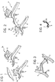
- two front lateral nodal structures respectively left and right, symmetrical to each other and generally indicated 1a and 1b, are initially produced.
- each front nodal structure 1a, 1b comprises a respective shaped element 2, in which a dome 3 is formed for fixing an associated front suspension, a front longitudinal beam 4, a shaped rear beam portion 5 and a lower support element 6 for attaching an arm of the suspension.
- the front longitudinal beams 4 are channel-shape metal elements formed, for example, by extrusion.
- the shaped element 2, the rear beam portion 5 and the lower support 6 are, however, preferably formed by pressing.
- the longitudinal beam 4 has an end welded to a corresponding end of the rear beam portion 5, and these beams 4 and 5 are in turn welded to a side of the shaped element 2.
- the support element 6 is welded both to the shaped element 2 and the beams 4 and 5.
- the front nodal structures 1a and 1b are interconnected by means of a first, substantially channel shape ( Figures 3 and 4) cross beam 7.
- the ends of the cross beam 7 are juxtaposed at the margins or edges of notches or seats 5a in the beam portions 5 of the nodal structures 1a and 1b ( Figure 1), and are welded there at a plurality of weld points 8 ( Figures 3 and 4).
- the cross beam 7 can advantageously be formed from pressed sheet steel.
- the construction of the chassis then continues with the welding of two longitudinal elements 10a and 10b, respectively left and right (Figure 5), to the distal ends of the rear beams 5 of the nodal structures 1a and 1b.
- the longitudinal elements 10a and 10b are substantially channel-shape, with respective folded upper edges or margins which extend essentially in a horizontal plane.
- the longitudinal elements 11 can advantageously be formed as shaped metal elements, for example, as extruded elements.
- the longitudinal elements 10a and 10b extend substantially co-planar and parallel to each other from opposite sides to the front longitudinal beams 4 connected to the nodal structures 1a and 1b.
- the construction of the chassis continues with the interconnection by welding of a second cross beam 12 to the ends of the longitudinal elements 10a and 10b opposite the aforesaid front nodal structures.
- the front edge of the cross beam 12 has two hollow formations 13a and 13b, respectively left and right, juxtaposed and form coupled to the ends of the longitudinal elements 10a and 10b (see also Figures 8 and 9) and welded thereto at a plurality of points to form a second rigid and geometrically stable subframe of the assembly, generally indicated 14 in Figures 7 and 8.
- the cross beam 12 can be formed from pressed sheet steel.
- the reference numerals 15a and 15b indicate two rear lateral nodal structures, respectively left and right, symmetrical to each other. These nodal structures comprise respective shaped bodies 16, formed from pressed sheet steel, with associated front projections 17, upper projections 18 and rear projections 19.
- Respective rear longitudinal beams 20a, 20b are welded to the projections 19 of the nodal structures 15a and 15b, which beams project, essentially parallel to each other, from the opposite sides of the subframe 14.
- the front ends 17 of the said rear nodal structures are juxtaposed and welded to the ends of the cross beam 12.
- the rear beams 20a, 20b, together with the cross beam 21, can advantageously be formed as shaped metal elements, for example, by extrusion.
- two essentially rectangular panels 22a, 22b, and a lower dashboard panel 23 are then fixed to the rigid structure formed in this way.
- the lower dashboard panel 23 rests on and is welded to the rear beams 5 which extend from the front nodal structures 1a and 1b, as well as on the front cross beam 7.
- the panels or footplates 22a and 22b intended generally to form the floor of the motor vehicle body, rest on and are welded to the longitudinal members 10a, 10b on the front margin of the cross beam 12, and on the rear margin of the lower dashboard panel 23.
- This latter has a slot 24 ( Figure 14) which extends from its rear margin to its longitudinally intermediate zone.
- the panel 23 has two facing folded edges 25 which connect respective, correspondingly upwardly folded longitudinal flanges 26a and 26b, of the panels or footwell plates 22a and 22b.
- a tunnel element, indicated 27 in Figure 15, is then applied and welded to the structure thus formed.
- This tunnel element has an aperture 28 in its central zone intended to enable the gear stick to pass through in known way.
- the tunnel element 27 is juxtaposed with the panels or footwell plates 22a and 22b, with its lateral skirts or flanges in contact with the upwardly folded edges 26a and 26b of the said panels or footwell plates.
- the rear arcuate edge of the tunnel element 27 is juxtaposed and welded to an arcuate intermediate portion 12a of the cross beam 12 ( Figure 16).
- the panels or footwell plates 22a, 22b, the panel 23 below the dashboard, and the tunnel element 27 are advantageously formed from pressed sheet steel.
- a dashboard reinforcement 30 (Figure 17) and a rear floor panel 31 (Figure 18) are then applied and welded to the structure of Figure 16.
- the dashboard reinforcement 30 and the rear floor panel 31 are advantageously formed from pressed sheet steel.
- the rear floor panel 31 has a front flange or hip 32, with an arcuate central portion 33 for form-coupling with and welding to the cross beam 12.
- the floor panel 31 further rests against and is welded to the rear nodal structures 15a and 15b, as well as to the cross beam 21 and the rear beams 20a and 20b.
- a hollow seat 34 ( Figures 18 to 20) can be provided in the flooring panel 31 for housing a spare wheel.
- Two side plates 36a and 36b are then applied and welded to the front nodal structures 1a and 1b, as well as to the lateral edges or margins of the dashboard frame 30, the panel below the dashboard and the footwell plates 22a and 22b.
- the side plates 36a and 36b are advantageously formed from pressed sheet steel.
- Two lateral longitudinal elements 37a and 37b are then applied and welded to the side edges of the footwell plates 22a and 22b.
- the front ends of the lateral longitudinal elements 37a, 37b are juxtaposed and welded to the rear ends of the corresponding side plates 36a, 36b.
- the rear ends of the longitudinal elements are, in turn, juxtaposed and welded to the side edges of the rear floor panel 31.
- Figure 21 substantially shows the basic structure of a motor vehicle, and is subsequently completed by the juxtaposition and welding of further constituent elements, in a substantially known way.
- the structure produced as described above advantageously includes a large number of elements or components that are metal profile sections. By virtue of this characteristic, the costs of development and manufacture of the chassis can be reduced considerably.
- pressed sheet steel elements are limited to those structural parts requiring the utmost precision of execution, high structural strength, or which have shapes unsuitable for formation from profile sections.
- the attachment and support elements for members and devices are advantageously concentrated in the front and rear nodal structures and are formed as pressed elements, with a consequent precision of execution and mutual positioning.
- chassis or base realised in the way described above lends itself to production by way of highly automated installations, with assembly and welding lines of the so-called "pick and place” type and/or on tacking lines of the so-called “skid” type.
- the base or chassis structure described above enables, using only a limited number of modified structural elements, the chassis to be easily adapted for models of motor vehicle having different characteristics, for example, having different lengths, different front and rear projections, and different body widths.
Landscapes
- Engineering & Computer Science (AREA)
- Chemical & Material Sciences (AREA)
- Combustion & Propulsion (AREA)
- Transportation (AREA)
- Mechanical Engineering (AREA)
- Body Structure For Vehicles (AREA)
- Automobile Manufacture Line, Endless Track Vehicle, Trailer (AREA)
Applications Claiming Priority (2)
| Application Number | Priority Date | Filing Date | Title |
|---|---|---|---|
| ITTO980636 IT1303162B1 (it) | 1998-07-21 | 1998-07-21 | Procedimento per la realizzazione di un telaio di un autoveicolo, etelaio realizzato con il procedimento. |
| ITTO980636 | 1998-07-21 |
Publications (2)
| Publication Number | Publication Date |
|---|---|
| EP0974509A1 true EP0974509A1 (de) | 2000-01-26 |
| EP0974509B1 EP0974509B1 (de) | 2003-08-20 |
Family
ID=11416944
Family Applications (1)
| Application Number | Title | Priority Date | Filing Date |
|---|---|---|---|
| EP19990113992 Expired - Lifetime EP0974509B1 (de) | 1998-07-21 | 1999-07-19 | Herstellungsverfahren eines Kraftfahrzeugchassis, und Chassis dadurch hergestellt |
Country Status (4)
| Country | Link |
|---|---|
| EP (1) | EP0974509B1 (de) |
| DE (1) | DE69910505T2 (de) |
| ES (1) | ES2205652T3 (de) |
| IT (1) | IT1303162B1 (de) |
Cited By (5)
| Publication number | Priority date | Publication date | Assignee | Title |
|---|---|---|---|---|
| EP1400437A3 (de) * | 2002-09-18 | 2004-06-02 | Fuji Jukogyo Kabushiki Kaisha | Vorderbau eines Fahrzeugs |
| CN100493975C (zh) * | 2007-05-30 | 2009-06-03 | 东风汽车公司 | 由桁架梁与板件结合的车身地板 |
| CN104129438A (zh) * | 2013-12-20 | 2014-11-05 | 中国重汽集团柳州运力专用汽车有限公司 | 车厢底板纵梁及其加工方法 |
| CN109501867A (zh) * | 2018-09-26 | 2019-03-22 | 北京长城华冠汽车科技股份有限公司 | 框架式车身后舱结构及焊接方法 |
| WO2021080887A1 (en) * | 2019-10-25 | 2021-04-29 | Caterpillar Inc. | Space frame center upper frame connection |
Families Citing this family (6)
| Publication number | Priority date | Publication date | Assignee | Title |
|---|---|---|---|---|
| DE102014204516B4 (de) * | 2013-03-26 | 2023-06-22 | Subaru Corporation | Fahrzeugkarosseriestruktur |
| FR3026079A1 (fr) | 2014-09-18 | 2016-03-25 | Peugeot Citroen Automobiles Sa | Structure multi-materiaux de vehicule automobile |
| DE102014016045A1 (de) * | 2014-10-29 | 2016-05-04 | GM Global Technology Operations LLC (n. d. Ges. d. Staates Delaware) | Fahrzeug-Unterbaustruktur |
| CN109204543B (zh) * | 2017-06-30 | 2020-11-06 | 比亚迪股份有限公司 | 车身结构和车辆 |
| CN109018023B (zh) * | 2018-08-27 | 2024-04-02 | 海马新能源汽车有限公司 | 可变车身结构 |
| DE102019100906B4 (de) * | 2019-01-15 | 2020-08-06 | Bayerische Motoren Werke Aktiengesellschaft | Vorderwagenstruktur für ein Kraftfahrzeug, insbesondere für einen Personenkraftwagen, sowie Kraftfahrzeug, insbesondere Personenkraftwagen |
Citations (4)
| Publication number | Priority date | Publication date | Assignee | Title |
|---|---|---|---|---|
| EP0297057A1 (de) * | 1987-06-23 | 1988-12-28 | FIAT AUTO S.p.A. | Modulare Karosserieeinheit für Kraftfahrzeuge |
| DE19708404A1 (de) * | 1996-03-03 | 1997-10-30 | Stromboli Ag | Fahrzeug |
| EP0823366A2 (de) * | 1996-07-30 | 1998-02-11 | Dr.Ing.h.c. F. Porsche Aktiengesellschaft | Federbeinaufnahme für ein Kraftfahrzeug, insbesondere Personenkraftwagen |
| DE19633908A1 (de) * | 1996-08-22 | 1998-02-26 | Bayerische Motoren Werke Ag | Bodengruppe für ein Fahrzeug |
-
1998
- 1998-07-21 IT ITTO980636 patent/IT1303162B1/it active IP Right Grant
-
1999
- 1999-07-19 ES ES99113992T patent/ES2205652T3/es not_active Expired - Lifetime
- 1999-07-19 EP EP19990113992 patent/EP0974509B1/de not_active Expired - Lifetime
- 1999-07-19 DE DE69910505T patent/DE69910505T2/de not_active Expired - Fee Related
Patent Citations (4)
| Publication number | Priority date | Publication date | Assignee | Title |
|---|---|---|---|---|
| EP0297057A1 (de) * | 1987-06-23 | 1988-12-28 | FIAT AUTO S.p.A. | Modulare Karosserieeinheit für Kraftfahrzeuge |
| DE19708404A1 (de) * | 1996-03-03 | 1997-10-30 | Stromboli Ag | Fahrzeug |
| EP0823366A2 (de) * | 1996-07-30 | 1998-02-11 | Dr.Ing.h.c. F. Porsche Aktiengesellschaft | Federbeinaufnahme für ein Kraftfahrzeug, insbesondere Personenkraftwagen |
| DE19633908A1 (de) * | 1996-08-22 | 1998-02-26 | Bayerische Motoren Werke Ag | Bodengruppe für ein Fahrzeug |
Cited By (8)
| Publication number | Priority date | Publication date | Assignee | Title |
|---|---|---|---|---|
| EP1400437A3 (de) * | 2002-09-18 | 2004-06-02 | Fuji Jukogyo Kabushiki Kaisha | Vorderbau eines Fahrzeugs |
| CN100493975C (zh) * | 2007-05-30 | 2009-06-03 | 东风汽车公司 | 由桁架梁与板件结合的车身地板 |
| CN104129438A (zh) * | 2013-12-20 | 2014-11-05 | 中国重汽集团柳州运力专用汽车有限公司 | 车厢底板纵梁及其加工方法 |
| CN109501867A (zh) * | 2018-09-26 | 2019-03-22 | 北京长城华冠汽车科技股份有限公司 | 框架式车身后舱结构及焊接方法 |
| WO2021080887A1 (en) * | 2019-10-25 | 2021-04-29 | Caterpillar Inc. | Space frame center upper frame connection |
| US11235808B2 (en) | 2019-10-25 | 2022-02-01 | Caterpillar Inc. | Space frame center upper frame connection |
| CN114641426A (zh) * | 2019-10-25 | 2022-06-17 | 卡特彼勒公司 | 空间框架中心上框架连接 |
| CN114641426B (zh) * | 2019-10-25 | 2023-09-19 | 卡特彼勒公司 | 中心上框架连接和关于中心上框架连接的方法 |
Also Published As
| Publication number | Publication date |
|---|---|
| DE69910505D1 (de) | 2003-09-25 |
| ES2205652T3 (es) | 2004-05-01 |
| DE69910505T2 (de) | 2004-04-08 |
| ITTO980636A1 (it) | 2000-01-21 |
| EP0974509B1 (de) | 2003-08-20 |
| IT1303162B1 (it) | 2000-10-30 |
Similar Documents
| Publication | Publication Date | Title |
|---|---|---|
| JPH0423116Y2 (de) | ||
| US4986597A (en) | Vehicle space frame and a method for manufacturing of vehicle space frame parts | |
| US7500802B2 (en) | Three-dimensional node structure | |
| EP0568213B1 (de) | Verbindungsstück für ein Fahrzeuggerüst-Gestell | |
| EP0974509B1 (de) | Herstellungsverfahren eines Kraftfahrzeugchassis, und Chassis dadurch hergestellt | |
| US6540286B2 (en) | Body structure | |
| EP1093995B1 (de) | Fahrzeugaufbaukonstruktion | |
| JP2816484B2 (ja) | 車両のフロア部構造 | |
| JPH1183U (ja) | 大型自動車用運転台構造物 | |
| EP2155535B1 (de) | Verfahren zur konstruktion der lasttragenden struktur einer fahrzeugkarosserie und auf diese weise konstruierte lasttragende struktur | |
| JP2007501736A (ja) | 車両支持体フレームにおいて2つの形材を連結するジャンクション構造 | |
| KR102107967B1 (ko) | 차대 프레임 결합용 연결부재 및 이를 이용한 차량의 가변형 차대 모듈 | |
| DE102004002276A1 (de) | Selbsttragendes großflächiges Karosseriebauteil an Kraftfahrzeugen und Verfahren zur Herstellung desselben | |
| KR970010582B1 (ko) | 보강 사이드패널이 구비된 자동차의 프론트바디 어셈블리 | |
| JP3091188B1 (ja) | フロアトンネルとクロスメンバとの接合部の構造 | |
| JP2944924B2 (ja) | ルーフパネルのリインホースメント取付構造 | |
| JPH0379477A (ja) | 自動車の前部車体構造 | |
| CN220615958U (zh) | 加强件、车身以及车辆 | |
| JP4368300B2 (ja) | 自動車の後部車体構造 | |
| US20230264759A1 (en) | Frame Joint Structure and Method | |
| JP2650468B2 (ja) | サイドメンバ接合構造 | |
| JPS60199774A (ja) | オ−プンカ−の車体 | |
| JPH0617664Y2 (ja) | 自動車のリヤピラー部構造 | |
| JPH07309252A (ja) | 自動車の後部車体構造 | |
| JP4147611B2 (ja) | 車輌のフロントピラーとカウルとの連結構造及び連結方法 |
Legal Events
| Date | Code | Title | Description |
|---|---|---|---|
| PUAI | Public reference made under article 153(3) epc to a published international application that has entered the european phase |
Free format text: ORIGINAL CODE: 0009012 |
|
| AK | Designated contracting states |
Kind code of ref document: A1 Designated state(s): DE ES FR GB SE |
|
| AX | Request for extension of the european patent |
Free format text: AL;LT;LV;MK;RO;SI |
|
| 17P | Request for examination filed |
Effective date: 20000630 |
|
| AKX | Designation fees paid |
Free format text: DE ES FR GB SE |
|
| 17Q | First examination report despatched |
Effective date: 20020531 |
|
| GRAH | Despatch of communication of intention to grant a patent |
Free format text: ORIGINAL CODE: EPIDOS IGRA |
|
| GRAH | Despatch of communication of intention to grant a patent |
Free format text: ORIGINAL CODE: EPIDOS IGRA |
|
| RAP1 | Party data changed (applicant data changed or rights of an application transferred) |
Owner name: FIAT AUTO S.P.A. |
|
| GRAA | (expected) grant |
Free format text: ORIGINAL CODE: 0009210 |
|
| AK | Designated contracting states |
Designated state(s): DE ES FR GB SE |
|
| REG | Reference to a national code |
Ref country code: GB Ref legal event code: FG4D |
|
| REF | Corresponds to: |
Ref document number: 69910505 Country of ref document: DE Date of ref document: 20030925 Kind code of ref document: P |
|
| REG | Reference to a national code |
Ref country code: SE Ref legal event code: TRGR |
|
| REG | Reference to a national code |
Ref country code: ES Ref legal event code: FG2A Ref document number: 2205652 Country of ref document: ES Kind code of ref document: T3 |
|
| PGFP | Annual fee paid to national office [announced via postgrant information from national office to epo] |
Ref country code: SE Payment date: 20040601 Year of fee payment: 6 |
|
| PGFP | Annual fee paid to national office [announced via postgrant information from national office to epo] |
Ref country code: ES Payment date: 20040603 Year of fee payment: 6 |
|
| PGFP | Annual fee paid to national office [announced via postgrant information from national office to epo] |
Ref country code: GB Payment date: 20040614 Year of fee payment: 6 |
|
| ET | Fr: translation filed | ||
| PLBE | No opposition filed within time limit |
Free format text: ORIGINAL CODE: 0009261 |
|
| STAA | Information on the status of an ep patent application or granted ep patent |
Free format text: STATUS: NO OPPOSITION FILED WITHIN TIME LIMIT |
|
| 26N | No opposition filed |
Effective date: 20040524 |
|
| PG25 | Lapsed in a contracting state [announced via postgrant information from national office to epo] |
Ref country code: GB Free format text: LAPSE BECAUSE OF NON-PAYMENT OF DUE FEES Effective date: 20050719 |
|
| PG25 | Lapsed in a contracting state [announced via postgrant information from national office to epo] |
Ref country code: SE Free format text: LAPSE BECAUSE OF NON-PAYMENT OF DUE FEES Effective date: 20050720 Ref country code: ES Free format text: LAPSE BECAUSE OF NON-PAYMENT OF DUE FEES Effective date: 20050720 |
|
| EUG | Se: european patent has lapsed | ||
| GBPC | Gb: european patent ceased through non-payment of renewal fee |
Effective date: 20050719 |
|
| PGFP | Annual fee paid to national office [announced via postgrant information from national office to epo] |
Ref country code: DE Payment date: 20060616 Year of fee payment: 8 |
|
| PGFP | Annual fee paid to national office [announced via postgrant information from national office to epo] |
Ref country code: FR Payment date: 20060731 Year of fee payment: 8 |
|
| REG | Reference to a national code |
Ref country code: ES Ref legal event code: FD2A Effective date: 20050720 |
|
| PG25 | Lapsed in a contracting state [announced via postgrant information from national office to epo] |
Ref country code: DE Free format text: LAPSE BECAUSE OF NON-PAYMENT OF DUE FEES Effective date: 20080201 |
|
| REG | Reference to a national code |
Ref country code: FR Ref legal event code: ST Effective date: 20080331 |
|
| PG25 | Lapsed in a contracting state [announced via postgrant information from national office to epo] |
Ref country code: FR Free format text: LAPSE BECAUSE OF NON-PAYMENT OF DUE FEES Effective date: 20070731 |