EP0973652B1 - Tire having low rolling resistance, in particular for driving wheels of heavy vehicles - Google Patents
Tire having low rolling resistance, in particular for driving wheels of heavy vehicles Download PDFInfo
- Publication number
- EP0973652B1 EP0973652B1 EP98906888A EP98906888A EP0973652B1 EP 0973652 B1 EP0973652 B1 EP 0973652B1 EP 98906888 A EP98906888 A EP 98906888A EP 98906888 A EP98906888 A EP 98906888A EP 0973652 B1 EP0973652 B1 EP 0973652B1
- Authority
- EP
- European Patent Office
- Prior art keywords
- tire
- tread
- slits
- grooves
- blocks
- Prior art date
- Legal status (The legal status is an assumption and is not a legal conclusion. Google has not performed a legal analysis and makes no representation as to the accuracy of the status listed.)
- Expired - Lifetime
Links
Images


Classifications
-
- B—PERFORMING OPERATIONS; TRANSPORTING
- B60—VEHICLES IN GENERAL
- B60C—VEHICLE TYRES; TYRE INFLATION; TYRE CHANGING; CONNECTING VALVES TO INFLATABLE ELASTIC BODIES IN GENERAL; DEVICES OR ARRANGEMENTS RELATED TO TYRES
- B60C11/00—Tyre tread bands; Tread patterns; Anti-skid inserts
- B60C11/03—Tread patterns
- B60C11/13—Tread patterns characterised by the groove cross-section, e.g. for buttressing or preventing stone-trapping
- B60C11/1369—Tie bars for linking block elements and bridging the groove
-
- B—PERFORMING OPERATIONS; TRANSPORTING
- B60—VEHICLES IN GENERAL
- B60C—VEHICLE TYRES; TYRE INFLATION; TYRE CHANGING; CONNECTING VALVES TO INFLATABLE ELASTIC BODIES IN GENERAL; DEVICES OR ARRANGEMENTS RELATED TO TYRES
- B60C11/00—Tyre tread bands; Tread patterns; Anti-skid inserts
- B60C11/03—Tread patterns
- B60C11/0306—Patterns comprising block rows or discontinuous ribs
- B60C11/0309—Patterns comprising block rows or discontinuous ribs further characterised by the groove cross-section
-
- B—PERFORMING OPERATIONS; TRANSPORTING
- B60—VEHICLES IN GENERAL
- B60C—VEHICLE TYRES; TYRE INFLATION; TYRE CHANGING; CONNECTING VALVES TO INFLATABLE ELASTIC BODIES IN GENERAL; DEVICES OR ARRANGEMENTS RELATED TO TYRES
- B60C11/00—Tyre tread bands; Tread patterns; Anti-skid inserts
- B60C11/03—Tread patterns
- B60C11/12—Tread patterns characterised by the use of narrow slits or incisions, e.g. sipes
- B60C11/1236—Tread patterns characterised by the use of narrow slits or incisions, e.g. sipes with special arrangements in the tread pattern
- B60C11/125—Tread patterns characterised by the use of narrow slits or incisions, e.g. sipes with special arrangements in the tread pattern arranged at the groove bottom
-
- B—PERFORMING OPERATIONS; TRANSPORTING
- B60—VEHICLES IN GENERAL
- B60C—VEHICLE TYRES; TYRE INFLATION; TYRE CHANGING; CONNECTING VALVES TO INFLATABLE ELASTIC BODIES IN GENERAL; DEVICES OR ARRANGEMENTS RELATED TO TYRES
- B60C11/00—Tyre tread bands; Tread patterns; Anti-skid inserts
- B60C11/03—Tread patterns
- B60C11/12—Tread patterns characterised by the use of narrow slits or incisions, e.g. sipes
- B60C11/1272—Width of the sipe
- B60C11/1281—Width of the sipe different within the same sipe, i.e. enlarged width portion at sipe bottom or along its length
-
- B—PERFORMING OPERATIONS; TRANSPORTING
- B60—VEHICLES IN GENERAL
- B60C—VEHICLE TYRES; TYRE INFLATION; TYRE CHANGING; CONNECTING VALVES TO INFLATABLE ELASTIC BODIES IN GENERAL; DEVICES OR ARRANGEMENTS RELATED TO TYRES
- B60C11/00—Tyre tread bands; Tread patterns; Anti-skid inserts
- B60C11/03—Tread patterns
- B60C11/12—Tread patterns characterised by the use of narrow slits or incisions, e.g. sipes
- B60C11/1204—Tread patterns characterised by the use of narrow slits or incisions, e.g. sipes with special shape of the sipe
- B60C2011/1213—Tread patterns characterised by the use of narrow slits or incisions, e.g. sipes with special shape of the sipe sinusoidal or zigzag at the tread surface
-
- B—PERFORMING OPERATIONS; TRANSPORTING
- B60—VEHICLES IN GENERAL
- B60C—VEHICLE TYRES; TYRE INFLATION; TYRE CHANGING; CONNECTING VALVES TO INFLATABLE ELASTIC BODIES IN GENERAL; DEVICES OR ARRANGEMENTS RELATED TO TYRES
- B60C11/00—Tyre tread bands; Tread patterns; Anti-skid inserts
- B60C11/03—Tread patterns
- B60C11/12—Tread patterns characterised by the use of narrow slits or incisions, e.g. sipes
- B60C11/1236—Tread patterns characterised by the use of narrow slits or incisions, e.g. sipes with special arrangements in the tread pattern
- B60C2011/1254—Tread patterns characterised by the use of narrow slits or incisions, e.g. sipes with special arrangements in the tread pattern with closed sipe, i.e. not extending to a groove
-
- Y—GENERAL TAGGING OF NEW TECHNOLOGICAL DEVELOPMENTS; GENERAL TAGGING OF CROSS-SECTIONAL TECHNOLOGIES SPANNING OVER SEVERAL SECTIONS OF THE IPC; TECHNICAL SUBJECTS COVERED BY FORMER USPC CROSS-REFERENCE ART COLLECTIONS [XRACs] AND DIGESTS
- Y02—TECHNOLOGIES OR APPLICATIONS FOR MITIGATION OR ADAPTATION AGAINST CLIMATE CHANGE
- Y02T—CLIMATE CHANGE MITIGATION TECHNOLOGIES RELATED TO TRANSPORTATION
- Y02T10/00—Road transport of goods or passengers
- Y02T10/80—Technologies aiming to reduce greenhouse gasses emissions common to all road transportation technologies
- Y02T10/86—Optimisation of rolling resistance, e.g. weight reduction
-
- Y—GENERAL TAGGING OF NEW TECHNOLOGICAL DEVELOPMENTS; GENERAL TAGGING OF CROSS-SECTIONAL TECHNOLOGIES SPANNING OVER SEVERAL SECTIONS OF THE IPC; TECHNICAL SUBJECTS COVERED BY FORMER USPC CROSS-REFERENCE ART COLLECTIONS [XRACs] AND DIGESTS
- Y10—TECHNICAL SUBJECTS COVERED BY FORMER USPC
- Y10S—TECHNICAL SUBJECTS COVERED BY FORMER USPC CROSS-REFERENCE ART COLLECTIONS [XRACs] AND DIGESTS
- Y10S152/00—Resilient tires and wheels
- Y10S152/03—Slits in threads
Definitions
- this invention relates to a tread as defined in the preamble portion of claim 1 as well as to a tire for vehicles which includes the same.
- the invention refers to a tread and a tire which are preferably, however not exclusively, used on driving wheels of heavy vehicles adapted to cover long travels in motorways.
- block is used to indicate a tread portion comprised between consecutive grooves or slits either in the axial or in the circumferential direction.
- grooves and “slits” are used to indicate channels formed in the tire tread and having a width greater than and, respectively, equal to or smaller than 1 mm.
- axial and axially are intended to indicate quantities measured along the peripheral -surface of the tire in a direction perpendicular to the equatorial plane of the same.
- the difficulty of fully satisfying the above need is essentially related to the difficulty of reducing the tire rolling resistance without substantially affecting its performances in terms of Telec yield, good traction capacity, stability on wet or snow grounds, and good lateral stability.
- Japanese application No. 7-172112 which corresponds to the preamble of claim 1, a tire which displays an excellent performance on icy and snowy road surfaces in an initial wear period and an excellent traveling performance on ordinary road surfaces as from an intermediate wear period onward, having a block pattern having a plurality of transversal grooves which are provided with groove-bottom sipes, which extend in a direction and are substantially in line with the transverse grooves direction.
- the technical problem underlying the present invention is to provide a tread and a tire having structural and functional features which allow to reduce the tire rolling resistance while keeping the tire performances at a very satisfactory level in terms of Telec yield, good traction and stability on wet or snow grounds, and good performances of lateral stability.
- a tread for vehicle tires in particular a pre-moulded tread for cold-covering worn tires as defined in appended claim 1.
- the Applicant has found in particular that by forming, in an equatorial zone of the tread, transversal grooves provided with slits downwardly extending therefrom, it is advantageously possible to achieve both adequate traction characteristics and the desired lower rolling resistance, essentially associated to the overall lower mobility of the tread blocks under the tire ground-contacting area due to the mutual contact of adjoining blocks caused by a closure of the slits.
- the equatorial zone of the tread concerned by the transversal grooves provided with slits in their lower part extends astride the equatorial plane of the tire and up to the middle of the longitudinal grooves for a length comprised between 40% and 70% of the axial development of the tire tread.
- such equatorial zone extends astride the equatorial plane of the tire for a length comprised between 50% and 60% of the axial development of the tread.
- the tread portions in which the equatorial blocks are formed are so-to-say embedded into one another under the ground-contacting area of the tire, because of the strains which the tread undergoes during tire rolling.
- the ensuing stiffness increase reduces the energy dissipation phenomena due both to the mobility of the blocks and to the physical-mechanical characteristics of the rubber composition of the tread, with a reduction of rolling resistance during running.
- a further and important advantageous effect attained by the particular structure of the transversal grooves is represented by the achievement of a better wear regularity, which is also associated to some extent to the stiffness increase of the tread equatorial blocks.
- the tread is circumferentially provided with a couple of longitudinal slits extending in opposite parts of the equatorial plane of the tire, which slits axially separate the equatorial blocks and split the transversal grooves formed therein into two portions proximal and, respectively, distal with respect to the equatorial plane of the tire.
- the longitudinal slits contribute both to increase the tire road holding in the axial direction, whenever the same is stressed in a transversal direction with respect to the rolling direction, and to prevent the triggering of phenomena of irregular wear of the blocks.
- the longitudinal slits extend along substantially the whole circumferential development of the tire according to an essentially zigzag path, which advantageously enhances the embedding between axially adjoining blocks, with a further reduction in energy dissipation phenomena due to block mobility in the longitudinal direction.
- the transversal grooves preferably have a reduced depth compared to the tires of the known art, and such as not to exceed 18 mm together with the slits downwardly extending from their bottom.
- the transversal grooves have a depth ranging between 1 and 4 mm in the portion proximal to the equatorial plane of the tire and a depth ranging between 5 and 10 mm in the portion distal to said equatorial plane.
- the sum of the depths of the transversal grooves and of the slits downwardly extending therefrom has a substantially constant value along the axial development of the same and is comprised between 13 and 18 mm.
- the slits downwardly extending from the bottom of the grooves have a depth comprised between 60% and 90% of the sum of the depths of the transversal grooves and said slits.
- the slits downwardly extending from the bottom of the grooves have a depth of between 40% and 70% of the sum of the depths of the transversal grooves and said slits.
- both the transversal grooves and the slits downwardly extending from their bottom extend substantially along the entire axial development of the blocks and have at least a substantially zigzag-shaped portion.
- the substantially zigzag-shaped portion is, located in the portion of transversal grooves and of the slits distal with respect to the equatorial plane of the tire.
- such embedding effect between tread portions concerned by adjoining equatorial blocks can be promoted by forming substantially as a cusp - i.e. by causing an abrupt inclination change with respect to its axial development - at least a portion of the transversal grooves and of the slits downwardly extending therefrom.
- the substantially cusp-shaped portion is located in the portion of the transversal grooves and of the slits proximal to the equatorial plane of the tire.
- the path of the transversal grooves and of the related slits forms a segmented line wherein at least a substantially zigzag-shaped portion and a substantially cusp-shaped portion are both present.
- the transversal grooves and the slits downwardly extending therefrom confer a directional characteristics to the tread pattern, i.e. they impart a preferred rolling direction to the tire.
- the invention may also be implemented according to non-directional (symmetrical or asymmetrical) tread patterns that lack such preferred rolling direction.
- the transversal grooves have a width that increases moving away from the equatorial plane of the tire, so as to enhance the tire capacity of draining off the water present under the tire ground-contacting area and reduce the aquaplaning phenomena.
- the transversal grooves advantageously form an angle ( ⁇ ) of from 10° to 25° with respect to a plane perpendicular to the equatorial plane of the tire.
- At least one of the blocks formed in the equatorial zone of the tread has a beveled corner at a longitudinal groove formed astride the equatorial plane of the tire and/or at the longitudinal grooves circumferentially extending in a direction substantially parallel to the tire rolling direction.
- the longitudinal grooves extend substantially along the whole circumferential development of the tire, according to a substantially zigzag-shaped path.
- the tire of the invention further comprises a plurality of lateral blocks, having an outer surface provided with facets, formed in opposite side zones of the tread external to said equatorial zone.
- the outer faceted surface of said lateral blocks effectively contributes to reach the desired traction characteristics of the tread in the tire rolling direction.
- At least one of said lateral blocks has a beveled corner at the longitudinal grooves circumferentially extending in a direction substantially parallel to the tire rolling direction and/or at its own outer faceted surface.
- the tire of the invention preferably has a high solid/total volume ratio under its ground-contacting area.
- the overall volume taken up by the blocks (equatorial and lateral) i.e. the volume of the solids in a tread portion having a length equal to the pitch of the tread pattern and a width equal to the tread axial development, is preferably comprised between 80% and 85% of the overall volume of said tread portion.
- axial development of the tread is used to indicate the extension in width of the latter as measured along the peripheral surface of the tire.
- pitch of the tread pattern is used to indicate the length, measured along the circumferential development of the tread, of a portion of the tread pattern which periodically repeats for a finite number "n" of times throughout the whole circumferential development of the tread.
- the pitch of the tread pattern is equal to the distance between the starting points of two subsequent repetitive portions of the tread pattern, measured along the circumferential development of the tread.
- the volume of the solids i.e. the volume taken up by the equatorial blocks
- the volume taken up by the lateral blocks is slightly lower, in order to improve the traction characteristics and is comprised between 75% and 85% of the overall volume of said tread portion.
- the tire and the tread of the invention may be manufactured by means of a process comprising a plurality of production steps which are quite conventional per se and known in the art.
- such process comprises the steps of preliminarly and independently preparing several semi-finished products corresponding to the different parts of the tire (carcass plies, belt strips, bead wires, fillings, sidewalls and treads), which are successively assembled to one another by means of a suitable assembling machine.
- the subsequent vulcanisation step then welds together the above semi-finished products to form an integral block, i.e., the tire.
- the step of preparing the above semi-finished products is preceded by a step of preparing and forming the corresponding rubber compositions, which comprise at least an unsaturated chain cross-linkable polymer base.
- suitable polymer bases are those selected from among the group comprising: natural rubber, 1,4-cis polybutadiene, polychloroprene, 1,4-cis polyisoprene, optionally halogenated isoprene-isobutene copolymers, either prepared in solution or in emulsion, ethylene-propylene-diene terpolymers.
- the aforementioned polymer bases are used in the rubber composition in such quantities and proportions as to achieve a tread abradability - determined according to Standards DIN 53516 - not exceeding 70 mm 3 .
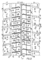
- 1 indicates a tire for vehicles according to the invention, in particular a tire suitable for long motorway mileage, and intended for being mounted on the drive wheel of a truck and full trailer or a tractor and semitrailer.
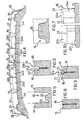
- the tire 1 comprises a carcass structure 2 including a central crown portion 3 and two sidewalls 4, 5, said carcass being provided with a reinforcing ply 2a the opposite side edges 2b, 2c of which are bent around respective bead cores 6, 7.
- an elastomeric filling 8 is applied which fills the zone defined between the reinforcing ply 2a and the corresponding side edges 2b, 2c of the reinforcing ply 2a.
- the opposite zones of the tire comprising each of the bead cores 6, 7 and the filling 8 form the so-called beads, globally indicated by 9 and 10, intended for anchoring the tire 1 on a corresponding mounting rim 11 of a vehicle wheel.
- a tread 14 by means of which the tire 1 gets in touch with the ground, is applied onto the belt structure 12.
- the tread 14 comprises a plurality of blocks 15, indicated in the following by the term: equatorial blocks, located on opposite parts of an equatorial plane Y-Y of the tire between a longitudinal groove 16 formed astride said equatorial plane, and a couple of longitudinal grooves 17, 18, circumferentially extending in a direction substantially parallel to the tire rolling direction, indicated by arrow D in Figure 2.
- equatorial blocks located on opposite parts of an equatorial plane Y-Y of the tire between a longitudinal groove 16 formed astride said equatorial plane, and a couple of longitudinal grooves 17, 18, circumferentially extending in a direction substantially parallel to the tire rolling direction, indicated by arrow D in Figure 2.
- the longitudinal groove 16 is provided with a rib 32, extending from bottom 33 of the same, intended for preventing tear formation in the rubber composition and for protecting the underlying belt structure 12 ( Figure 5).
- the longitudinal grooves 17, 18 extend substantially along the whole circumferential development of the tire 1 according to a substantially zigzag-shaped path.
- the equatorial blocks 15 are circumferentially separated by a plurality of slits 19 extending in a direction substantially perpendicular to the rolling direction D of tire 1.
- the equatorial zone E of the tread concerned by blocks 15 extends astride the equatorial plane Y-Y of tire 1 for a width of from 50% to 60% of the axial development of the tread.
- the equatorial zone E extends astride the equatorial plane of the tire Y-Y for a width equal to about 55% of the axial development of the tread 14.
- the tread 14 further comprises a plurality of transversal grooves 20, pitchwise spaced from one another and extending parallel to slits 19 in a direction substantially perpendicular to the rolling direction D of the tire.
- Each of the transversal grooves 20 comprises in turn a bottom 21 connected to opposite inlet and, respectively, outlet sidewalls 22, 23 having a predetermined inclination with respect to the axis of the same groove ( Figures 6 and 9).
- inlet and outlet are used to indicate - with reference to the structural features of the transversal grooves 20 - the parts of the grooves which are stressed first or get in touch first with the ground during rolling of the tire 1 and, respectively, the parts of the grooves 20 that are stressed after a predetermined angular rotation of the wheel.
- upstream and downstream are used to indicate - with reference to the position of the transversal grooves 20 - those parts of the tread 14, for instance the rubber blocks 15, that are stressed or get in touch with the ground during rolling of the tire 1 before and, respectively, after said grooves 20.
- the grooves 20 are provided in their lower part with respective slits 24 downwardly extending from the bottom 21 of the same.
- the tread 14 is circumferentially provided with a couple of longitudinal slits 25 that extend in opposite parts of the equatorial plane Y-Y of the tire 1.
- the longitudinal slits 25 split the equatorial blocks 15 in the axial direction, splitting them into two groups of proximal blocks 15a and, respectively, distal blocks 15b with respect to the equatorial plane Y-Y of the tire ( Figure 2).
- the longitudinal slits 25 axially split the transversal grooves 20 and the slits 24, downwardly extending from the same, into two portions respectively proximal 20a, 24a, and distal 20b, 24b with respect to the equatorial plane Y-Y of the tire ( Figure 4).
- the longitudinal slits 25 contribute both to increase the road holding in the axial direction of the tread whenever tire 1 is stressed in a transversal direction with respect to the rolling direction D and to avoid the triggering of irregular wear phenomena of the equatorial blocks 15.
- the longitudinal slits 25 extend substantially along the whole circumferential development of the tire 1 according to a substantially zigzag-shaped path which advantageously enhances the embedding between axially adjoining portions of the equatorial grooves 15, with a further reduction of the energy dissipation phenomena during rolling of the tire 1.
- the transversal grooves 20 preferably have a depth not exceeding 18 mm.
- the transversal grooves 20 have a depth of from 1 to 4 mm in the portion 15a of the blocks proximal to the equatorial plane Y-Y of tire 1, and a depth of from 5 to 10 mm in the portion 15b of the blocks distal with respect to the equatorial plane Y-Y.
- the sum of the depths of the transversal grooves 20 and of the slits 24 downwardly extending therefrom takes on a substantially constant value along their axial development and is comprised between 13 and 18 mm.
- the slits 24 downwardly extending from bottom 21 of said grooves have a depth of from 60% to 90% of the sum of the depths of the transversal grooves 20 and of the slits 24.
- the slits 24 downwardly extending from bottom 21 of said grooves have a depth of from 40% to 70% of the sum of the depths of the transversal grooves 20 and of the slits 24.
- both the transversal grooves 20 and the slits 24 downwardly extending from bottom 21 of said grooves extend substantially along the whole development of the equatorial blocks 15a, 15b, according to a path forming a segmented line wherein at least a substantially zigzag-shaped portion and at least a substantially cusp-shaped portion are present.
- the substantially zigzag-shaped portion is located in portions 20b, 24b of the transversal grooves 20 and of the slits 24 distal with respect to the equatorial plane Y-Y of the tire 1.
- the substantially cusp-shaped portion is located in portions 20a, 24a of the transversal grooves 20 and of the slits 24 proximal with respect to the equatorial plane Y-Y of the tire 1.
- the embedding effect between portions of tread 14 concerned by adjoining equatorial blocks 15 is optimised, and the maximum effect of reduction of the energy dissipation phenomena - and therefore of rolling resistance of the tire 1 - is achieved.
- the transversal grooves 20 have a width that increases moving away from the equatorial plane Y-Y of the tire 1, so as to enhance the tire capacity of draining off the water present under the tire ground-contacting area and reduce the aquaplaning phenomena.
- the width of the transversal grooves 20 ranges from a minimum of 2 mm near the longitudinal groove 16 to a maximum of 10 mm near the opposite longitudinal grooves 17 and 18.
- the transversal grooves 20 advantageously form an angle ( ⁇ ) of between 10° and 25° with respect to a plane perpendicular to the equatorial plane Y-Y of the tire 1.
- At least one of the blocks 15a formed in the equatorial zone E of the tread 14 and proximal with respect to the equatorial plane Y-Y of the tire 1, has a beveled corner 26 near the longitudinal groove 16.
- At least one of the blocks 15b formed in the equatorial zone E of the tread 14 and distal with respect to the equatorial plane Y-Y of the tire 1, has a beveled corner 31 near the longitudinal grooves 17, 18 circumferentially extending in a direction substantially parallel to the rolling direction D of the tire.
- the tire of the invention further comprises a plurality of lateral blocks 27 defined in opposite side zones F, G of the tread 14, external to the equatorial zone E of the same.
- the lateral blocks 27 are longitudinally separated by a corresponding plurality of transversal grooves 34, extending between the longitudinal grooves 17 and 18 and opposite shoulder portions of the tread 14.
- the transversal grooves 34 have a constant width comprised between 7 and 12 mm.
- the lateral blocks 27 are also mutually connected and stiffened by a plurality of ribs 35 intended for increasing stiffness of the tread 14 at its own shoulder portions.
- each of the lateral blocks 27 is centrally provided with a transversal slit 36 the function of which is to increase the traction capacity of the tread 14 at the side zones F, G thereof.
- the axial development of the slit 36 may be limited to 10-15 mm as shown in the figures, or may extend up to cover to whole width of the lateral blocks 27.
- the lateral blocks 27 are provided with an outer surface 28 provided with facets 37, which effectively contributes to achieve the desired traction capacity of the tread 14 in the rolling direction D of the tire 1.
- At least one of lateral blocks 27 has a beveled corner 29 near its outer faceted surface 28.
- At least one of the lateral blocks 27 has a beveled corner 30 near the longitudinal grooves 17, 18, circumferentially extending in a direction substantially parallel to the rolling direction D of the tire 1.
- the volume taken up by the equatorial blocks 15, or volume of the solids, in a tread portion having a length equal to pitch "p" of the tread pattern, and a width equal to the axial development of the tread 14, is comprised between 80% and 90% of the overall volume of such tread portion.
- the volume taken up by the lateral blocks 27 in this same portion of the tread 14 is comprised between 75% and 85% of the overall volume of the same.
- the total volume of the solids (equatorial blocks 15 and lateral blocks 27) in the aforesaid portion of the tread 14 is comprised between 80% and 85% of the overall volume of the same.
Landscapes
- Engineering & Computer Science (AREA)
- Mechanical Engineering (AREA)
- Tires In General (AREA)
Applications Claiming Priority (3)
| Application Number | Priority Date | Filing Date | Title |
|---|---|---|---|
| IT97MI000103A IT1289182B1 (it) | 1997-01-20 | 1997-01-20 | Pneumatico a bassa resistenza di rotolamento in particolare per ruote motrici di veicoli pesanti |
| ITMI970103 | 1997-01-20 | ||
| PCT/EP1998/000387 WO1998031555A1 (en) | 1997-01-20 | 1998-01-16 | Tire having low rolling resistance, in particular for driving wheels of heavy vehicles |
Publications (2)
| Publication Number | Publication Date |
|---|---|
| EP0973652A1 EP0973652A1 (en) | 2000-01-26 |
| EP0973652B1 true EP0973652B1 (en) | 2001-10-31 |
Family
ID=11375677
Family Applications (1)
| Application Number | Title | Priority Date | Filing Date |
|---|---|---|---|
| EP98906888A Expired - Lifetime EP0973652B1 (en) | 1997-01-20 | 1998-01-16 | Tire having low rolling resistance, in particular for driving wheels of heavy vehicles |
Country Status (10)
| Country | Link |
|---|---|
| US (1) | US6415834B1 (ja) |
| EP (1) | EP0973652B1 (ja) |
| JP (1) | JP4165836B2 (ja) |
| AR (1) | AR011545A1 (ja) |
| AT (1) | ATE207820T1 (ja) |
| BR (1) | BR9807289A (ja) |
| DE (1) | DE69802275T2 (ja) |
| ES (1) | ES2167873T3 (ja) |
| IT (1) | IT1289182B1 (ja) |
| WO (1) | WO1998031555A1 (ja) |
Cited By (3)
| Publication number | Priority date | Publication date | Assignee | Title |
|---|---|---|---|---|
| EP2292448A1 (de) | 2009-09-02 | 2011-03-09 | Continental Reifen Deutschland GmbH | Fahrzeugluftreifen für Nutzfahrzeuge |
| DE102010000637A1 (de) | 2010-03-04 | 2011-09-08 | Continental Reifen Deutschland Gmbh | Fahrzeugluftreifen für Nutzfahrzeuge |
| DE102010016469A1 (de) | 2010-04-16 | 2011-10-20 | Continental Reifen Deutschland Gmbh | Fahrzeugluftreifen für Nutzfahrzeuge |
Families Citing this family (28)
| Publication number | Priority date | Publication date | Assignee | Title |
|---|---|---|---|---|
| GB2326386B (en) * | 1997-06-19 | 2001-11-21 | Sumitomo Rubber Ind | Vehicle tyre tread groove with radially inward extension |
| ATE229887T1 (de) * | 1998-10-29 | 2003-01-15 | Pirelli | Reifen und dessen lauffläche |
| GB9902449D0 (en) * | 1999-02-05 | 1999-03-24 | Sumitomo Rubber Ind | Tread for a pneumatic tyre |
| JP3405701B2 (ja) * | 1999-12-09 | 2003-05-12 | 住友ゴム工業株式会社 | 空気入りタイヤおよびそのタイヤ加硫金型 |
| EP1238827B1 (de) * | 2001-03-06 | 2004-11-03 | Continental Aktiengesellschaft | Reifenprofil |
| JP4209319B2 (ja) * | 2001-06-07 | 2009-01-14 | 株式会社ブリヂストン | オフザロードタイヤ |
| JP3682269B2 (ja) * | 2002-05-09 | 2005-08-10 | 住友ゴム工業株式会社 | 空気入りタイヤ |
| DE102004034116A1 (de) * | 2004-07-15 | 2006-02-02 | Continental Aktiengesellschaft | Fahrzeugluftreifen |
| FR2894183B1 (fr) * | 2005-12-06 | 2008-02-15 | Michelin Soc Tech | Bande de roulement pour pneumatique poids lourd |
| FR2909588B1 (fr) * | 2006-12-07 | 2009-01-16 | Michelin Soc Tech | Bande de roulement pourvue d'incisions a double orientation. |
| JP4488055B2 (ja) * | 2007-11-02 | 2010-06-23 | 横浜ゴム株式会社 | 空気入りタイヤ |
| JP4547012B2 (ja) * | 2008-02-18 | 2010-09-22 | 住友ゴム工業株式会社 | 空気入りタイヤ |
| US20100236681A1 (en) * | 2009-03-17 | 2010-09-23 | Daniel Ray Beha | Tire having tread blocks with blended walls |
| DE102009026086A1 (de) * | 2009-07-01 | 2011-01-05 | Continental Reifen Deutschland Gmbh | Fahrzeugluftreifen |
| JP5384402B2 (ja) | 2010-03-08 | 2014-01-08 | 株式会社ブリヂストン | 空気入りタイヤ |
| US9352619B2 (en) | 2010-03-08 | 2016-05-31 | Bridgestone Corporation | Pneumatic tire |
| JP5797412B2 (ja) * | 2011-01-21 | 2015-10-21 | 株式会社ブリヂストン | 空気入りタイヤ |
| JP6110586B2 (ja) * | 2011-01-21 | 2017-04-05 | 株式会社ブリヂストン | 空気入りタイヤ |
| JP5778497B2 (ja) * | 2011-06-21 | 2015-09-16 | 株式会社ブリヂストン | 重荷重用タイヤ |
| JP5476410B2 (ja) * | 2012-03-15 | 2014-04-23 | 住友ゴム工業株式会社 | 空気入りタイヤ |
| JP5993986B2 (ja) * | 2015-06-18 | 2016-09-21 | 株式会社ブリヂストン | 空気入りタイヤ |
| EP3176006B1 (en) * | 2015-11-24 | 2018-06-20 | Sumitomo Rubber Industries Limited | Tire |
| CN109203867B (zh) * | 2018-11-09 | 2020-10-27 | 青岛双星轮胎工业有限公司 | 胎面花纹及轮胎 |
| WO2020171223A1 (ja) * | 2019-02-22 | 2020-08-27 | 横浜ゴム株式会社 | 空気入りタイヤ |
| FR3094272A1 (fr) * | 2019-03-28 | 2020-10-02 | Compagnie Generale Des Etablissements Michelin | Pneumatique à couches de travail comprenant une architecture et une sculpture optimisées |
| JP7121695B2 (ja) * | 2019-06-19 | 2022-08-18 | 株式会社ブリヂストン | タイヤ |
| DE102020204072A1 (de) * | 2020-03-30 | 2021-09-30 | Continental Reifen Deutschland Gmbh | Fahrzeugluftreifen |
| JP6996584B2 (ja) * | 2020-04-03 | 2022-01-17 | 横浜ゴム株式会社 | タイヤ |
Family Cites Families (25)
| Publication number | Priority date | Publication date | Assignee | Title |
|---|---|---|---|---|
| FR2145414B1 (ja) * | 1971-07-13 | 1974-02-15 | Michelin & Cie | |
| DE2455130A1 (de) * | 1974-11-21 | 1976-05-26 | Continental Gummi Werke Ag | Luftreifen fuer kraftfahrzeuge |
| JPS58199204A (ja) * | 1982-05-12 | 1983-11-19 | Bridgestone Corp | 重荷重用空気入りラジアルタイヤ |
| JPS62155105A (ja) * | 1985-12-27 | 1987-07-10 | Sumitomo Rubber Ind Ltd | ブロツクパタ−ンタイヤ |
| US4690189A (en) * | 1986-01-29 | 1987-09-01 | The Goodyear Tire & Rubber Company | All-season pneumatic tire with chamfered tread blocks |
| JPS63312204A (ja) * | 1987-06-11 | 1988-12-20 | Bridgestone Corp | 空気入りラジアルタイヤ |
| JPH01195103A (ja) * | 1988-01-27 | 1989-08-07 | Sumitomo Rubber Ind Ltd | ラジアルタイヤ |
| EP0348335A3 (en) * | 1988-06-20 | 1991-02-27 | The Goodyear Tire & Rubber Company | Tire treads and tires |
| JP2872283B2 (ja) * | 1989-08-01 | 1999-03-17 | 株式会社ブリヂストン | 空気入りタイヤ |
| JP2800944B2 (ja) * | 1989-10-12 | 1998-09-21 | 住友ゴム工業 株式会社 | 空気入りタイヤ |
| FR2669273A1 (fr) * | 1990-11-15 | 1992-05-22 | Michelin & Cie | Bande de roulement d'enveloppe de pneumatique pour vehicules poids-lourds. |
| JPH04201610A (ja) * | 1990-11-30 | 1992-07-22 | Bridgestone Corp | 騒音を低減した空気入りタイヤ |
| JPH04201609A (ja) * | 1990-11-30 | 1992-07-22 | Bridgestone Corp | 氷結湿濡地表上での走行性能に優れる空気入りタイヤ |
| DE9016455U1 (ja) * | 1990-12-04 | 1991-07-25 | Uniroyal Englebert Reifen Gmbh, 5100 Aachen, De | |
| JPH04215505A (ja) * | 1990-12-14 | 1992-08-06 | Bridgestone Corp | 氷結湿濡地表上での走行性能に優れる空気入りタイヤ |
| SE505583C2 (sv) * | 1991-12-26 | 1997-09-15 | Sumitomo Rubber Ind | Däckmönster |
| JPH05178031A (ja) * | 1991-12-26 | 1993-07-20 | Sumitomo Rubber Ind Ltd | 空気入りタイヤ |
| JPH07172112A (ja) * | 1993-12-21 | 1995-07-11 | Bridgestone Corp | 空気入りタイヤ |
| IT1276320B1 (it) * | 1994-02-22 | 1997-10-28 | Pirelli | Pneumatico per veicoli da trasporto medio/pesante con battistrada di tipo universale |
| JP2966760B2 (ja) * | 1995-04-18 | 1999-10-25 | 住友ゴム工業株式会社 | 重荷重用タイヤ |
| FR2744067A1 (fr) * | 1996-01-30 | 1997-08-01 | Michelin & Cie | Bande de roulement pour pneumatique |
| CA2257612A1 (en) * | 1996-06-07 | 1997-12-11 | The Goodyear Tire & Rubber Company | A convertible tread for a radial truck or trailer tire |
| JP3136101B2 (ja) * | 1996-09-19 | 2001-02-19 | 住友ゴム工業株式会社 | 空気入りタイヤ |
| JP3158061B2 (ja) * | 1996-12-19 | 2001-04-23 | 住友ゴム工業株式会社 | 重荷重用ラジアルタイヤ |
| USD394034S (en) * | 1997-04-29 | 1998-05-05 | The Goodyear Tire & Rubber Company | Tire tread |
-
1997
- 1997-01-20 IT IT97MI000103A patent/IT1289182B1/it active IP Right Grant
-
1998
- 1998-01-16 EP EP98906888A patent/EP0973652B1/en not_active Expired - Lifetime
- 1998-01-16 JP JP53369998A patent/JP4165836B2/ja not_active Expired - Fee Related
- 1998-01-16 ES ES98906888T patent/ES2167873T3/es not_active Expired - Lifetime
- 1998-01-16 WO PCT/EP1998/000387 patent/WO1998031555A1/en active IP Right Grant
- 1998-01-16 DE DE69802275T patent/DE69802275T2/de not_active Expired - Fee Related
- 1998-01-16 BR BR9807289A patent/BR9807289A/pt not_active IP Right Cessation
- 1998-01-16 AT AT98906888T patent/ATE207820T1/de not_active IP Right Cessation
- 1998-01-20 AR ARP980100229A patent/AR011545A1/es active IP Right Grant
-
1999
- 1999-07-13 US US09/352,214 patent/US6415834B1/en not_active Expired - Fee Related
Cited By (4)
| Publication number | Priority date | Publication date | Assignee | Title |
|---|---|---|---|---|
| EP2292448A1 (de) | 2009-09-02 | 2011-03-09 | Continental Reifen Deutschland GmbH | Fahrzeugluftreifen für Nutzfahrzeuge |
| DE102010000637A1 (de) | 2010-03-04 | 2011-09-08 | Continental Reifen Deutschland Gmbh | Fahrzeugluftreifen für Nutzfahrzeuge |
| WO2011107171A1 (de) | 2010-03-04 | 2011-09-09 | Continental Reifen Deutschland Gmbh | Fahrzeugluftreifen für nutzfahrzeuge |
| DE102010016469A1 (de) | 2010-04-16 | 2011-10-20 | Continental Reifen Deutschland Gmbh | Fahrzeugluftreifen für Nutzfahrzeuge |
Also Published As
| Publication number | Publication date |
|---|---|
| WO1998031555A1 (en) | 1998-07-23 |
| EP0973652A1 (en) | 2000-01-26 |
| IT1289182B1 (it) | 1998-09-29 |
| JP2001508725A (ja) | 2001-07-03 |
| AR011545A1 (es) | 2000-08-30 |
| ITMI970103A1 (it) | 1998-07-20 |
| DE69802275D1 (de) | 2001-12-06 |
| US6415834B1 (en) | 2002-07-09 |
| JP4165836B2 (ja) | 2008-10-15 |
| ATE207820T1 (de) | 2001-11-15 |
| ES2167873T3 (es) | 2002-05-16 |
| BR9807289A (pt) | 2000-03-21 |
| DE69802275T2 (de) | 2002-07-18 |
Similar Documents
| Publication | Publication Date | Title |
|---|---|---|
| EP0973652B1 (en) | Tire having low rolling resistance, in particular for driving wheels of heavy vehicles | |
| US20020033214A1 (en) | Tire having low rolling resistance, in particular for driving wheels of heavy vehicles | |
| CA1271400A (en) | Asymmetrical tyres for vehicle wheels | |
| US6003574A (en) | Motor-vehicle pneumatic tire having a tread pattern for snow covered road surfaces | |
| US5733393A (en) | Tire having good diverse properties | |
| EP0485883B1 (en) | Winter type tire tread | |
| JP3177466B2 (ja) | 空気入りタイヤ | |
| US6170546B1 (en) | Heavy duty pneumatic tire including variable width grooves and constant width grooves | |
| EP0178859B1 (en) | Pneumatic radial tyre for heavy load vehicles | |
| EP0342908B1 (en) | Pneumatic tyre | |
| JP2774775B2 (ja) | 空気入りタイヤ | |
| US6450223B1 (en) | Pneumatic tire having improved wet traction | |
| CA2165004A1 (en) | Pneumatic tire having improved wet traction | |
| WO2011080565A1 (en) | Pneumatic tire for on road and off road use | |
| JP2872283B2 (ja) | 空気入りタイヤ | |
| CN110234520B (zh) | 汽车轮胎 | |
| JPH07186626A (ja) | 空気入りラジアルタイヤ | |
| EP0787600B1 (en) | A tire having good diverse properties | |
| JPS6154601B2 (ja) | ||
| JPH0687303A (ja) | 空気入りタイヤ | |
| JPS62152906A (ja) | 乗用車用空気入りラジアルタイヤ | |
| EP1021306B1 (en) | Tread for a pneumatic tire | |
| CN114599528A (zh) | 充气轮胎 | |
| JP2755353B2 (ja) | 重荷重用タイヤ | |
| JP3406687B2 (ja) | 空気入りラジアルタイヤ |
Legal Events
| Date | Code | Title | Description |
|---|---|---|---|
| PUAI | Public reference made under article 153(3) epc to a published international application that has entered the european phase |
Free format text: ORIGINAL CODE: 0009012 |
|
| 17P | Request for examination filed |
Effective date: 19990630 |
|
| AK | Designated contracting states |
Kind code of ref document: A1 Designated state(s): AT DE ES FR GB IT SE |
|
| GRAG | Despatch of communication of intention to grant |
Free format text: ORIGINAL CODE: EPIDOS AGRA |
|
| 17Q | First examination report despatched |
Effective date: 20010316 |
|
| GRAG | Despatch of communication of intention to grant |
Free format text: ORIGINAL CODE: EPIDOS AGRA |
|
| GRAH | Despatch of communication of intention to grant a patent |
Free format text: ORIGINAL CODE: EPIDOS IGRA |
|
| GRAH | Despatch of communication of intention to grant a patent |
Free format text: ORIGINAL CODE: EPIDOS IGRA |
|
| GRAA | (expected) grant |
Free format text: ORIGINAL CODE: 0009210 |
|
| AK | Designated contracting states |
Kind code of ref document: B1 Designated state(s): AT DE ES FR GB IT SE |
|
| REF | Corresponds to: |
Ref document number: 207820 Country of ref document: AT Date of ref document: 20011115 Kind code of ref document: T |
|
| REF | Corresponds to: |
Ref document number: 69802275 Country of ref document: DE Date of ref document: 20011206 |
|
| REG | Reference to a national code |
Ref country code: GB Ref legal event code: IF02 |
|
| ET | Fr: translation filed | ||
| REG | Reference to a national code |
Ref country code: ES Ref legal event code: FG2A Ref document number: 2167873 Country of ref document: ES Kind code of ref document: T3 |
|
| PLBE | No opposition filed within time limit |
Free format text: ORIGINAL CODE: 0009261 |
|
| STAA | Information on the status of an ep patent application or granted ep patent |
Free format text: STATUS: NO OPPOSITION FILED WITHIN TIME LIMIT |
|
| 26N | No opposition filed | ||
| PGFP | Annual fee paid to national office [announced via postgrant information from national office to epo] |
Ref country code: ES Payment date: 20080128 Year of fee payment: 11 |
|
| PGFP | Annual fee paid to national office [announced via postgrant information from national office to epo] |
Ref country code: SE Payment date: 20080129 Year of fee payment: 11 Ref country code: IT Payment date: 20080129 Year of fee payment: 11 Ref country code: GB Payment date: 20080129 Year of fee payment: 11 |
|
| PGFP | Annual fee paid to national office [announced via postgrant information from national office to epo] |
Ref country code: AT Payment date: 20080102 Year of fee payment: 11 |
|
| PGFP | Annual fee paid to national office [announced via postgrant information from national office to epo] |
Ref country code: FR Payment date: 20080117 Year of fee payment: 11 Ref country code: DE Payment date: 20080229 Year of fee payment: 11 |
|
| EUG | Se: european patent has lapsed | ||
| GBPC | Gb: european patent ceased through non-payment of renewal fee |
Effective date: 20090116 |
|
| PG25 | Lapsed in a contracting state [announced via postgrant information from national office to epo] |
Ref country code: DE Free format text: LAPSE BECAUSE OF NON-PAYMENT OF DUE FEES Effective date: 20090801 Ref country code: AT Free format text: LAPSE BECAUSE OF NON-PAYMENT OF DUE FEES Effective date: 20090116 |
|
| REG | Reference to a national code |
Ref country code: FR Ref legal event code: ST Effective date: 20091030 |
|
| PG25 | Lapsed in a contracting state [announced via postgrant information from national office to epo] |
Ref country code: GB Free format text: LAPSE BECAUSE OF NON-PAYMENT OF DUE FEES Effective date: 20090116 |
|
| REG | Reference to a national code |
Ref country code: ES Ref legal event code: FD2A Effective date: 20090117 |
|
| PG25 | Lapsed in a contracting state [announced via postgrant information from national office to epo] |
Ref country code: FR Free format text: LAPSE BECAUSE OF NON-PAYMENT OF DUE FEES Effective date: 20090202 Ref country code: ES Free format text: LAPSE BECAUSE OF NON-PAYMENT OF DUE FEES Effective date: 20090117 |
|
| PG25 | Lapsed in a contracting state [announced via postgrant information from national office to epo] |
Ref country code: IT Free format text: LAPSE BECAUSE OF NON-PAYMENT OF DUE FEES Effective date: 20090116 |
|
| PG25 | Lapsed in a contracting state [announced via postgrant information from national office to epo] |
Ref country code: SE Free format text: LAPSE BECAUSE OF NON-PAYMENT OF DUE FEES Effective date: 20090117 |