EP0971479B1 - Netzfilter - Google Patents
Netzfilter Download PDFInfo
- Publication number
- EP0971479B1 EP0971479B1 EP99112097A EP99112097A EP0971479B1 EP 0971479 B1 EP0971479 B1 EP 0971479B1 EP 99112097 A EP99112097 A EP 99112097A EP 99112097 A EP99112097 A EP 99112097A EP 0971479 B1 EP0971479 B1 EP 0971479B1
- Authority
- EP
- European Patent Office
- Prior art keywords
- bobbin
- line filter
- piece
- core
- hollow
- Prior art date
- Legal status (The legal status is an assumption and is not a legal conclusion. Google has not performed a legal analysis and makes no representation as to the accuracy of the status listed.)
- Expired - Lifetime
Links
Images


Classifications
-
- H—ELECTRICITY
- H01—ELECTRIC ELEMENTS
- H01F—MAGNETS; INDUCTANCES; TRANSFORMERS; SELECTION OF MATERIALS FOR THEIR MAGNETIC PROPERTIES
- H01F27/00—Details of transformers or inductances, in general
- H01F27/34—Special means for preventing or reducing unwanted electric or magnetic effects, e.g. no-load losses, reactive currents, harmonics, oscillations, leakage fields
-
- H—ELECTRICITY
- H03—ELECTRONIC CIRCUITRY
- H03H—IMPEDANCE NETWORKS, e.g. RESONANT CIRCUITS; RESONATORS
- H03H7/00—Multiple-port networks comprising only passive electrical elements as network components
- H03H7/42—Balance/unbalance networks
- H03H7/425—Balance-balance networks
- H03H7/427—Common-mode filters
-
- H—ELECTRICITY
- H03—ELECTRONIC CIRCUITRY
- H03H—IMPEDANCE NETWORKS, e.g. RESONANT CIRCUITS; RESONATORS
- H03H1/00—Constructional details of impedance networks whose electrical mode of operation is not specified or applicable to more than one type of network
- H03H2001/0021—Constructional details
- H03H2001/005—Wound, ring or feed-through type inductor
Definitions
- the present invention relates to a line filter that is capable of eliminating the common mode noise and the normal mode noise, for use in various domestic appliances.
- Fig. 29 is a perspective view of a conventional line filter.
- Fig. 30 is a cross sectional front view of the line filter.
- Fig. 31 is a chart of electric circuit used to describe transmission of a common mode noise in the line filter in operation.
- Fig. 32 is a chart of magnetic circuit used to describe flow of magnetic flux subject to a common mode noise in the line filter.
- a conventional line filter comprises a bobbin 72 having a through-hole 71, a first coil 73 and a second coil 74 wound around the bobbin 72, and a closed magnetic circuit core 75 which is inserted through the through-hole 71.
- magnetic flux AA and magnetic flux BB generated respectively from the first coil 73 and the second coil 74 proceed in a same direction in the magnetic core 75, in a manner they do not offset to each other.
- the magnetic flux AA generated from the first coil 73 and the magnetic flux BB generated from the second coil 74 proceed in a same direction inside the magnetic core 75; joining together, in a manner not offsetting to each other.
- a common mode current is called a common mode noise
- a normal mode noise is a common mode noise
- a conventional line filter of the above structure is capable of eliminating the common mode noise 76, but it is unable to eliminate the normal mode noise.
- JP 10 172842 and US 5 635 890 disclose such a conventional line filter, comprising a bobbin having a through-hole, first and second coils wound around said bobbin and a closed magnetic circuit core inserted through the through-hole of said bobbin.
- EP 0615260 further discloses such a conventional line filter comprising a bobbin having a through-hole, a first coil and a second coil wound around said bobbin, a closed magnetic circuit core inserted through the through-hole of said bobbin, said closed magnetic circuit core comprises a middle foot inserted in said through-hole and counterpart feet arranged outside of said bobbin encountering said middle foot; said bobbin is formed of piece-members of a bobbin split into two parallel pieces along a direction that is in parallel with the direction of said through-hole, the bobbin being formed by combining the piece-members at respective split faces, each of which piece-members having a middle flange for separating said first coil from said second coil.
- the present invention is intended to offer a line filter that is capable of eliminating the common mode noise and the normal mode noise altogether.
- a line filter in accordance with the present invention is defined in claim 1 and comprises a bobbin having a through-hole, a first coil and a second coil wound around the bobbin, a closed magnetic circuit core inserted through the through-hole of the bobbin, first noise elimination means for eliminating common mode noise, and second noise elimination means for eliminating normal mode noise.
- the first noise elimination means makes respective magnetic fluxes generated from the first coil and the second coil to proceed in a same direction in the magnetic core, in a mode not offsetting to each other, for the purpose of noise elimination.
- the second noise elimination means makes respective magnetic fluxes generated from the first coil and the second coil to proceed in opposite directions to each other, in a mode not offsetting to each other, for the purpose of noise elimination.
- the first noise elimination means eliminates the common mode noise
- the second noise elimination means eliminates the normal mode noise.
- the line filter eliminates both of the common mode noise and the normal mode noise altogether.
- a line filter is described in the following with reference to the drawings.
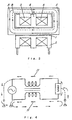
- a line filter comprises a bobbin 2 having a through-hole 1, a first coil 3 and a second coil 4 wound around the bobbin 2 and a closed magnetic circuit core 5 having a rectangularly cylindrical shape inserted through the through-hole 5.
- the bobbin 2 is provided with a middle flange 6 separating the first coil 3 from the second coil 4.
- the bobbin 2, inclusive of the middle flange 6, is made of a ferrite resin, which being a magnetic material.
- the line filter comprises first noise elimination means for eliminating a common mode noise 11, and second noise elimination means for eliminating a normal mode noise 12.
- the first noise elimination means makes respective magnetic flux A and magnetic flux B generated from the first coil 3 and the second coil 4 to proceed in a same direction in said magnetic core 5, in a mode not offsetting to each other, for the purpose of eliminating noise.
- the second noise elimination means makes respective magnetic flux A and magnetic flux B generated from the first coil 3 and the second coil 4 to proceed in opposite directions to each other in said magnetic core 5, in a mode not offsetting to each other; while the magnetic flux A and the magnetic flux B proceeding in a same direction within the middle flange 6, for the purpose of eliminating noise.
- the middle flange 6 is arranged adjacent to the magnetic core 5. Representing a distance between the bobbin and the magnetic core, viz, a distance of clearance between the outer circumferential surface 7of the middle flange 6 and the inner wall-surface 8 of the magnetic core 5 at a place above the outer circumferential surface 7, with a symbol H; the smallest value of H is not greater than the gap dimensions T (T1 + T2) between the inner wall-surface of the through-hole 1 of the bobbin 2 and the outer circumferential surface 10 of the magnetic core 5 being inserted in the through-hole 1, while the greatest value of H is not smaller than the gap dimensions T. Further, the outer circumferential surface 7 of the middle flange 6 of the bobbin 2 is not making contact with the inner wall-surface 8 of the magnetic core 5.
- first noise elimination means respective magnetic flux A and magnetic flux B generated from the first coil 3 and the second coil 4 proceed in a same direction in the closed magnetic circuit core 5, in a mode not offsetting to each other.
- the common mode noise 11 is eliminated in this way.
- second noise elimination means respective magnetic flux A and magnetic flux B generated from the first coil 3 and the second coil 4 proceed in opposite directions to each other in the magnetic core 5, in a mode not offsetting to each other.
- the normal mode noise 12 is eliminated in this way.
- the magnetic flux A and the magnetic flux B generated from the first coil 3 and the second coil 4 readily proceed in the middle flange 6.
- the magnetic flux A and the magnetic flux B are made to proceed in the magnetic core 5 in opposite directions to each other in a mode not offsetting to each other, the magnetic flux A and the magnetic flux B are naturally brought about to proceed in a same direction within the middle flange 6, and a magnetic flux A and a magnetic flux B is created around the first coil 3 and the second coil 4, respectively, to surely eliminate the normal mode noise 12.
- the middle flange 6 of the bobbin 2 is arranged to be adjacent to the magnetic core 5, the magnetic flux A and the magnetic flux B proceed in the middle flange 6 quite easily, and, around the first coil 3 and the second coil 4, respectively, a magnetic flux A and a magnetic flux B are created. This further enhances the sure elimination of normal mode noise 12.
- the distance H between bobbin and magnetic core is placed under a positional restriction, because the smallest value of H has been specified to be not greater than the gap dimension T (T1 + T2), and the greatest value of H has been specified to be not smaller than the gap dimension T.
- the closed magnetic circuit core 5 is simply allowed to go through in the through-hole 1, the distance H between bobbin and magnetic core might become very great, or very far away to each other, subject to a value of the gap dimension T (T1 + T2). In this case, it becomes difficult for the magnetic flux A and the magnetic flux B to proceed in the middle flange 6, and the effect of eliminating normal mode noise 12 may be ill affected.
- the middle flange 6 comes in touch with the magnetic core 5, the magnetic saturation easily arises and the characteristics of superimposed current deteriorate, which provides an adverse influence on the elimination of both the normal mode noise 12 and the common mode noise 11.
- a line filter of the above mentioned advantages uses a closed magnetic circuit core 5 having a rectangularly cylindrical shape
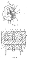
- a closed magnetic circuit core 13 having an EI joining cross-sectional shape as shown in Fig. 7 and Fig. 8 may be used instead for obtaining the same effects.
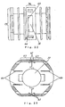
- the line filter comprises a bobbin 23 having a brim 21 at both ends and provided with a through-hole 22 between the brims 21, a first coil 24 and a second coil 25 wound around the bobbin 23, a closed magnetic circuit core 28 having a shape of the figure "8 " composed of a middle foot 26 inserted in the through-hole 22 and counterpart feet 27 arranged outside the bobbin 23 encountering the middle foot 26, a terminal board 29 for holding the magnetic core 28 horizontal, first noise elimination means for eliminating the common mode noise 30 and second noise elimination means for eliminating the normal mode noise 31.
- the second noise elimination means makes respective magnetic flux A generated from the first coil 24 and magnetic flux B generated from the second coil 25 to proceed in a same direction within a central magnetic core 32 disposed in the bobbin 23; while they proceed in opposite directions to each other in the magnetic core 28, in a mode not offsetting to each other.
- the second noise elimination means eliminates the normal mode noise 31.
- the first noise elimination means eliminates the common mode noise by making the magnetic flux A and the magnetic flux B to proceed, as shown in Fig. 15 and Fig. 16 , in a same direction in the magnetic core 28, in a mode not offsetting to each other.
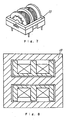
- the bobbin 23 is formed of two piece-members 33 of a bobbin, which had been split in a direction parallel to the through-hole 22 so as to be able to be recombined together at their split faces.
- Each of the piece-members 33 is provided with a middle flange 34 that separates the first coil 24 from the second coil 25.
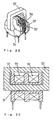
- the middle flange 34 is provided with a hollow 35 that is open towards the inner surface of the piece-member 33.
- a central magnetic core 32 made of a magnetic material is disposed in the hollow 35, and the hollow 35 is provided with hooking means for hooking the central magnetic core 32.
- the piece-member 33 is provided at the bottom of the hollow 35 with a through-window 36 penetrating to the outer surface towards the counterpart feet 27 of magnetic core 28.
- the central magnetic core 32 has a protrusion 37 extruding through the through-window 36. A part of the central magnetic core 32 is exposed to the closed magnetic circuit core 28, in a manner not making contact.
- the protrusion 37 has a step 38 that makes contact to the bottom surface of the hollow 35.
- the inner ceiling surface 39 and the inner bottom surface 40 of hollow 35 are horizontal planes, and the upper surface 41 and the lower surface 42 of central magnetic core 32 are also forming horizontal planes in accordance with the inner ceiling surface 39 and the inner bottom surface 40 of hollow 35.
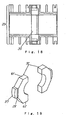
- hooking reeds 43 for hooking the central magnetic core 32, and a rib 44 is provided within the hollow 35 for elastically holding the central magnetic core 32.
- a hooking claw 45 for providing the central magnetic core 32 with a pressure effecting from the inner circumferential surface towards the outer circumferential surface of the piece-member 33.
- a slit 46 is provided at both sides of the hooking claw 45.
- Each of the piece-members 33 is provided with a splitting flange 47 for splitting a coil.
- the splitting flange 47 is disposed so as there is a gap 48 between the end of splitting flange 47 and the split face of piece-member 33. Wire of a first coil 24, or a second coil 25, is transferred across the splitting flange 47 by way of the gap 48.
- the piece-members 33 are disposed with their split faces in the vertical (direction Z) direction.
- Each of the piece-members 33 has horizontal planes at the upper surface 55 and the bottom surface 56.
- the split surface is provided with means for aligning the piece-members 33 to a right positioning to each other.
- the aligning means is formed of a first protruding wall 50 provided in parallel with the through-hole 22 and a second protruding wall 51 provided perpendicular to the through-hole 22 on the split face of piece-member 33.
- the first protruding wall 50 is provided for at least two with the through-hole 22 in between; the protruding walls 50 of each piece-member 33 are overlaid and held with a pressure to each other's.
- the second protruding wall 51 is provided for at least two with the middle flange 34 in between; the protruding walls 51 of each piece-member 33 are overlaid and held with a pressure to each other's.
- the terminal board 29 is provided with a terminal wall 52, which is arranged vertically to face the outer circumference of the bobbin 23.
- the terminal wall 52 has a cut 53 at a place corresponding to the middle flange 34 of bobbin 23.
- An adhesive agent is applied in the cut 53 for gluing the closed magnetic circuit core 28, the bobbin 23 and the terminal board 29 together.
- the outer dimensions in horizontal directions of the terminal board 29 are greater than those of the closed magnetic circuit core 28 in the horizontal directions.
- the common mode noise 30 is eliminated by the first noise elimination means.
- the normal mode noise 31 is eliminated by the second noise elimination means, where respective magnetic flux A generated from the first coil 24 and magnetic flux B generated from the second coil 25 are made to proceed in a same direction within the central magnetic core 32, while they proceed in opposite directions to each other in the closed magnetic circuit core 28 in a mode that the magnetic flux A and the magnetic flux B are not offsetting to each other. In this way, both of the common mode noise 30 and the normal mode noise 31 are eliminated altogether.
- the central magnetic core 32 made of a magnetic material is disposed in the hollow 35 of the middle flange 26.
- the hollow 35 is open towards inside of the piece-member 33, and is provided with hooking means for hooking the central magnetic core 32; therefore, the central magnetic core 32 does not fall off the piece-member 33.
- the hooking means for hooking the central magnetic core 32 provided in the hollow 35 the central magnetic core 32 is fixed steady in the hollow 35, and the positioning of central magnetic core 32 relative to the hollow 35 can be precisely determined. Accordingly, the positioning of central magnetic core 32 relative to the closed magnetic circuit core 28 is also determined with a precision. Because of the above described structure, the elimination of normal mode noise 31 will not be affected adversely by a possible falling of the central magnetic core 32 off the piece-member 33, or by a possible contacting with the magnetic core 28.
- the first coil 24 and the second coil 25 are wound around the bobbin 23 by rotating the bobbin 23 around the middle foot 26, after first disposing the central magnetic core 32 in the hollow 35, and then combining the piece-members 33 together.
- the central magnetic core 32 is secured in place by a centrifugal force effected by the rotation for coil winding; so it does not fall off the piece-member 33 of bobbin.
- the central magnetic core 32 may not be dislocated within the hollow 35; therefore, a trouble such as making contact with the middle foot 26 will not arise, which trouble might sometimes cause a broken central magnetic core 32.
- a part of the central magnetic core 28 is exposed through the through-window 36 provided in the bottom of the hollow 35 at a location facing to the counterpart feet 27 of the closed magnetic circuit core 28. This contributes to a reduction of the magnetic resistance between the central magnetic core 32 and the closed magnetic circuit core 28. This leads to an increased accuracy in eliminating the normal mode noise 31.
- a protrusion 37 provided in the central magnetic core 32 makes a further contribution to a reduction of the magnetic resistance between the central magnetic core 32 and the closed magnetic circuit core 28, which provides a further improvement in the increased accuracy in the elimination of normal mode noise 31.
- a distance between the central magnetic core 32 and the closed magnetic circuit core 28 can be easily determined for an optimum magnetic resistance.
- the hooking means comprises a hooking reed 43 provided at both ends of the hollow 35 for hooking the central magnetic core 32. Therefore, the location of the central magnetic core 32 relative to the hollow 35 can be fixed precisely by the hooking means.
- central magnetic core 32 relative to the closed magnetic circuit core 28 is also determined precisely. Because of the above described structure, elimination of the normal mode noise 31 will not be ill affected by a possible falling of the central magnetic core 32 off the piece-member 33 of bobbin, or by a possible contacting with the magnetic core 28.
- a hooking claw 45 that pushes the central magnetic core 32 from the inner circumferential surface towards the outer circumferential surface of the piece-member 33. Therefore, the central magnetic core 32 is fixed firm within the hollow 35 with the location relative to the hollow 35 precisely determined.
- a rib 44 is provided within the hollow 35 for elastically holding the central magnetic core 32, the location of central magnetic core 32 relative to the hollow 35 can be determined at a higher precision level.
- the protrusion 37 is extruding from the through-window 36. This contributes to surely fix the central magnetic core 32.
- the location of the central magnetic core 32 relative to the hollow 35 can be determined at a supreme precision level.
- the hooking reed 43 is provided with a slit 46, the central magnetic core 32 is held with an elasticity when it is placed in the hollow 35 of the middle flange 34.
- the moderated pressure of hooking reed 43 prevents occurrence of a possible breakage on the central magnetic core 32.
- the inner ceiling surface 39 and the inner bottom surface 40 of the hollow 35 have been finished to be horizontal planes, and the upper surface 41 and the lower surface 42 of the central magnetic core 32 are also finished to be horizontal planes in accordance with the inner ceiling surface 39 and the inner bottom surface 40 of the hollow 35. Therefore, the positioning of the central magnetic core 32 is regulated to a right direction within the hollow 35, and insertion of the central magnetic core 32 into the hollow 35 is easy.
- the positioning direction of the central magnetic core 32 within the hollow 35 is regulated a step more stringent.
- Each of the piece-members 33 of bobbin has been disposed so as its split face is positioned vertical, and its upper surface 55 and lower surface 56 are made to from horizontal planes. This can be an advantage in a trial for reducing the overall height.
- Each of the split faces of the piece-members 33 is provided with position regulating means for regulating each other's positioning. Therefore, the piece-members 33 can easily be positioned to a right orientation in terms of relative location.
- the respective first protruding walls 50 of the piece-members 33 are engaged overlaid together, and the second protruding walls 51 are also engaged overlaid together. Therefore, positioning between the couple of piece-members 33 is regulated in both vertical and horizontal directions.
- the above described structure also contributes to make the creeping distance in terms of electrical insulation longer; which offers an additional advantage in preventing occurrence of an insulation failure.
- each of the piece-members 33 is provided with at least two first protruding walls 50 and two second protruding walls 52 for engagement of corresponding walls with a pressure, the combined piece-members 33 are surely united to form a bobbin.
- the winding of a coil 24, or a coil 25, may be shifted easily across the splitting flange 47 by making use of the gap 48 provided in the piece-members 33 of a bobbin.
- the terminal wall 52 provided vertically on the terminal board 29 effectively insulates the first coil 24 and the second coil 25 from the closed magnetic circuit core 28.
- the closed magnetic circuit core 28, the bobbin 23 and the terminal board 29 can be glued together by applying an adhesive agent 54 in the cut 53 provided in the terminal wall 52.
- an adhesive agent 54 in one place completes the gluing operation; which makes a contribution in improving the productivity during manufacturing operation.
- the empty space within the through-hole 22 of bobbin 23 is not filled with anything.
- the space may be filled with a magnetic resin made of magnetic material, as shown in Fig. 27 ; providing a magnetic resin member 57, which occupies the empty space within the through-hole 22 and the hollow 35.
- the magnetic resin member 57 occupying the empty space within the through-hole 22 and the hollow 35 contributes to improve the magnetic characteristics, and to regulate the middle foot 26, the central magnetic core 32 and the bobbin 23 to a right positioning. It also contributes to suppress beating of the closed magnetic circuit core 28 and the central magnetic core 32.
- a piece-member 33 may be provided with a plurality of splitting flanges 47, with the end locations 58 of adjacent splitting flanges 47 displaced one another in an oblique direction as illustrated in Fig. 28 . If a winding of the first coil 24, or the second coil 25, is transferred from a span specified by the splitting flanges 47 to an adjacent span across the splitting flange 47 that has been disposed in the above described layout, the number of winding turns in a span will increase.
- a closed magnetic circuit core 28 having a an EI joining cross-sectional shape has been used in the present exemplary embodiment, a magnetic core having a rectangularly cylindrical shape may be used instead for yielding the same effect.
- a line filter in accordance with the present invention is capable of eliminating both the common mode noise and the normal mode noise altogether.
- the central magnetic core will not fall off the piece-member of a bobbin, which central magnetic core is surely fixed in a hollow and its positioning and the direction within the hollow are precisely regulated.
- the relative positioning between the central magnetic core and the closed magnetic circuit core are determined and maintained precisely.
- the occurrence of such troubles as falling of the central magnetic core off the piece-member, touching of the central magnetic core to the closed magnetic circuit core can be prevented.
- an adverse influence that could affect the elimination of normal mode noise is avoided.
- the central magnetic core is held firm in the piece-member under the effect of a centrifugal force generated by the rotation of bobbin; the central magnetic core would not fall off the piece-member, nor would it cause dislocation within the hollow during the rotation, such dislocation may be leading to a touching with, or even to a breakage of, the middle foot of closed magnetic circuit core.
- the present invention offers a line filter that has an improved characteristic in eliminating the normal mode noise, and is capable of eliminating both the common mode noise and the normal mode noise altogether.
Claims (21)
- Netzfilter mit:einem Spulenkörper (23), der ein Durchgangsloch (22) hat;einer ersten Spule (24) und einer zweiten Spule (25), die um den Spulenkörper gewickelt sind;einem geschlossenen Magnetkreiskern (28), der durch das Durchgangsloch des Spulenkörpers gesteckt ist,
wobeider geschlossene Magnetkreiskern einen Mittelfuß (26), der in dem Durchgangsloch steckt, und Gegenfüße aufweist, die außerhalb des Spulenkörpers angeordnet sind und auf den Mittelfuß treffen, undder Spulenkörper (23) aus Spulenkörper-Elementen (33) besteht, die in zwei parallele Teile entlang einer Richtung unterteilt sind, die parallel zu der Richtung des Durchgangslochs verläuft, wobei der Spulenkörper durch Verbinden der Elemente an entsprechenden Trennflächen hergestellt wird, wobei jedes der Elemente einen Mittelflansch (34) zum Trennen der ersten Spule (24) von der zweiten Spule (25) hat,
dadurch gekennzeichnet, dassder Mittelflansch eine Vertiefung (35) aufweist, deren Öffnung zu der Innenfläche des Elements zeigt,ein mittiger Magnetkern (32), der aus einem magnetischen Material besteht, in der Vertiefung vorgesehen ist unddie Vertiefung mit Einrastmitteln zum Einrasten des mittigen Magnetkerns versehen ist. - Netzfilter nach Anspruch 1, dadurch gekennzeichnet, dass die Vertiefung (35) mit einem Durchgangsfenster (36) an der Unterseite versehen ist, das zu der Außenfläche eines Elements hindurchgeht, wobei das Durchgangsfenster an einer Stelle gegenüber den Gegenfüßen (27) des geschlossenen Magnetkreiskerns angeordnet ist und ein Teil des mittigen Magnetkerns durch das Durchgangsfenster hindurch freiliegt.
- Netzfilter nach Anspruch 2, dadurch gekennzeichnet, dass der mittige Magnetkern mit einem Vorsprung (37) versehen ist, der durch das Durchgangsfenster (36) hindurch vorspringt.
- Netzfilter nach Anspruch 1, dadurch gekennzeichnet, dass die Einrastmittel aus einer Einrastzunge (43) bestehen, die an beiden Enden der Vertiefung zum Einrasten des mittigen Magnetkerns vorgesehen sind.
- Netzfilter nach Anspruch 4, dadurch gekennzeichnet, dass die Einrastzunge (43) an dem Spitzenende mit einer Einrastkralle (45) versehen ist, um den mittigen Magnetkern von der Innenfläche zu der Außenfläche eines Elements eines Spulenkörpers zu drücken.
- Netzfilter nach Anspruch 5, dadurch gekennzeichnet, dass die Einrastzunge (43) mit einem Schlitz (46) versehen ist.
- Netzfilter nach Anspruch 1, dadurch gekennzeichnet, dass die Einrastmittel aus einer Rippe (44) bestehen, die in der Vertiefung zum Festhalten des mittigen Magnetkerns mit einem Druck vorgesehen ist.
- Netzfilter nach Anspruch 1, dadurch gekennzeichnet, dass die Einrastmittel aus einem Durchgangsfenster, das an der Unterseite der Vertiefung vorgesehen ist, die zu der Außenfläche eines Elements des Spulenkörpers hindurchgeht, und einem Vorsprung des mittigen Magnetkerns besteht, der durch das Durchgangsfenster vorspringt.
- Netzfilter nach Anspruch 4, Anspruch 7 oder Anspruch 8, dadurch gekennzeichnet, dass die innere Deckenfläche und die innere Bodenfläche der Vertiefung horizontale Ebenen sind und die Oberseite und die Unterseite des mittigen Magnetkerns horizontale Ebenen sind, die der inneren Deckenfläche und der inneren Bodenfläche der Vertiefung entsprechen.
- Netzfilter nach Anspruch 8, dadurch gekennzeichnet, dass der Vorsprung (37) mit einem Absatz (38) versehen ist, der in Kontakt mit dem Boden der Vertiefung kommt.
- Netzfilter nach Anspruch 1, dadurch gekennzeichnet, dass das Element des Spulenkörpers so angeordnet ist, dass sich die Schlitzseite in der vertikalen Richtung befindet, und das Element eine horizontale Ebene an der Ober- und der Unterseite hat.
- Netzfilter nach Anspruch 1, dadurch gekennzeichnet, dass das Element des Spulenkörpers an der Trennungsfläche mit Ausrichtungsmitteln zum Ausrichten der Elemente für eine richtige relative Positionierung zueinander versehen ist.
- Netzfilter nach Anspruch 12, dadurch gekennzeichnet, dass die Ausrichtungsmittel zum Ausrichten für eine richtige relative Positionierung aus einer ersten vorspringenden Wand (50), die in einer Richtung parallel zu dem Durchgangsloch vorgesehen ist, und einer zweiten vorspringenden Wand (51) bestehen, die senkrecht zu dem Durchgangsloch auf den entsprechenden Trennflächen von Elementen vorgesehen ist, wobei entsprechende Wände der ersten vorspringenden Wand in den Elementen des Spulenkörpers übereinander angeordnet sind und entsprechende Wände der zweiten vorspringenden Wand in den Elementen des Spulenkörpers übereinander angeordnet sind.
- Netzfilter nach Anspruch 13, dadurch gekennzeichnet, dass die erste vorspringende Wand (50) vorgesehen ist für mindestens zwei, mit dem Durchgangsloch dazwischen, entsprechende Wände der ersten vorspringenden Wand in Elementen eines Spulenkörpers übereinander angeordnet und mit einem Druck aneinander gehalten werden, während die zweite vorspringende Wand (51) vorgesehen ist für mindestens zwei, mit dem Mittelflansch (34) dazwischen, entsprechende Wände der zweiten vorspringenden Wand in Elementen des Spulenkörpers übereinander angeordnet und mit einem Druck aneinander gehalten werden.
- Netzfilter nach Anspruch 1, dadurch gekennzeichnet, dass die Elemente (33) des Spulenkörpers mit einer Vielzahl von Trennflanschen (47) zum Trennen einer Spule versehen sind, wobei die Trennflansche so angeordnet sind, dass es einen Spalt (48) zwischen dem Ende des Trennflansches (47) und der Trennfläche des Elements (33) gibt, der es ermöglicht, dass ein Fenster einer Spule in einem von den Trennflanschen festgelegten Bereich durch den Spalt zu einem benachbarten Bereich verschoben werden kann.
- Netzfilter nach Anspruch 15, dadurch gekennzeichnet, dass die Trennflansche (47) so angeordnet sind, dass die Enden von benachbarten Trennflanschen nacheinander in einer schrägen Richtung verschoben werden.
- Netzfilter nach Anspruch 1, das weiterhin eine Endplatte (29) zum horizontalen Halten des geschlossenen Magnetkreiskerns aufweist, wobei die Endplatte eine Endwand (52) hat, die vertikal zwischen dem Spulenkörper (23) und dem geschlossenen Magnetkreiskern (28) steht, wobei sie zu der Außenfläche der ersten Spule und der zweiten Spule zeigt, wobei die Endwand mit einer Kerbe (53) an einer Stelle versehen ist, die dem Mittelflansch (34) entspricht, der den mittigen Magnetkern aufnimmt,
wobei der geschlossene Magnetkreiskern, der Spulenkörper und die Endplatte mit einem Klebstoff verleimt sind, der in der Kerbe aufgebracht wird. - Netzfilter nach Anspruch 17, dadurch gekennzeichnet, dass
der Mittelflansch (34) mit einem Durchgangsfenster (36) versehen ist, das zu der Außenfläche eines Elements eines Spulenkörpers hindurchgeht, wobei das Durchgangsfenster an einer Stelle angeordnet ist, die den Gegenfüßen des geschlossenen Magnetkreiskerns gegenüberliegt, sodass ein Teil des mittigen Magnetkerns freiliegt, und
der geschlossene Magnetkreiskern, der Spulenkörper, die Endplatte und der mittige Magnetkreiskern mit einem Klebstoff verleimt sind, der in der Kerbe (53) aufgebracht wird. - Netzfilter nach Anspruch 1, das weiterhin eine Endplatte (29) zum horizontalen Halten des geschlossenen Magnetkreiskerns aufweist, wobei die Außenabmessungen der Endplatte größer als die des geschlossenen Magnetkreiskerns sind.
- Netzfilter nach Anspruch 1, dadurch gekennzeichnet, dass ein magnetisches Harzteil (57) durch Füllen von leeren Räumen in dem Durchgangsloch und der Vertiefung eines Spulenkörpers mit einem magnetischen Harz hergestellt wird.
- Netzfilter nach Anspruch 1, dadurch gekennzeichnet, dass der mittige Magnetkern und der geschlossene Magnetkreiskern nicht miteinander in Kontakt kommen.
Applications Claiming Priority (4)
| Application Number | Priority Date | Filing Date | Title |
|---|---|---|---|
| JP10185996A JP2000021658A (ja) | 1998-07-01 | 1998-07-01 | ラインフィルタ |
| JP18599698 | 1998-07-01 | ||
| JP36916498 | 1998-12-25 | ||
| JP36916498A JP3436162B2 (ja) | 1998-12-25 | 1998-12-25 | ラインフィルタ |
Publications (3)
| Publication Number | Publication Date |
|---|---|
| EP0971479A2 EP0971479A2 (de) | 2000-01-12 |
| EP0971479A3 EP0971479A3 (de) | 2002-05-08 |
| EP0971479B1 true EP0971479B1 (de) | 2011-03-02 |
Family
ID=26503463
Family Applications (1)
| Application Number | Title | Priority Date | Filing Date |
|---|---|---|---|
| EP99112097A Expired - Lifetime EP0971479B1 (de) | 1998-07-01 | 1999-06-23 | Netzfilter |
Country Status (6)
| Country | Link |
|---|---|
| US (1) | US6078242A (de) |
| EP (1) | EP0971479B1 (de) |
| KR (1) | KR100318589B1 (de) |
| CN (1) | CN1179375C (de) |
| DE (1) | DE69943233D1 (de) |
| TW (1) | TW413825B (de) |
Families Citing this family (19)
| Publication number | Priority date | Publication date | Assignee | Title |
|---|---|---|---|---|
| TW504714B (en) | 2000-01-14 | 2002-10-01 | Matsushita Electric Ind Co Ltd | Line filter |
| DE10157796A1 (de) * | 2001-11-27 | 2003-06-05 | Abb Research Ltd | Dreidimensionale Wicklungsanordnung |
| JP4461931B2 (ja) * | 2003-08-08 | 2010-05-12 | 国産電機株式会社 | インバータユニット |
| TWI334612B (en) * | 2004-10-15 | 2010-12-11 | Delta Electronics Inc | Emi filter |
| JP4858035B2 (ja) * | 2006-09-19 | 2012-01-18 | トヨタ自動車株式会社 | リアクトルのコアおよびリアクトル |
| US20080074227A1 (en) * | 2006-09-21 | 2008-03-27 | Ford Global Technologies, Llc | Inductor topologies with substantial common-mode and differential-mode inductance |
| CN201112050Y (zh) * | 2007-10-06 | 2008-09-10 | 台达电子工业股份有限公司 | 一种电感器的基座 |
| JP5385083B2 (ja) * | 2009-10-19 | 2014-01-08 | 東京パーツ工業株式会社 | ラインフィルタ |
| JP5638416B2 (ja) * | 2011-02-18 | 2014-12-10 | 株式会社マキタ | 電動工具 |
| CN102195467A (zh) * | 2011-06-01 | 2011-09-21 | 江苏泰昌电子有限公司 | 一种沉板式滤波器 |
| TWI439698B (zh) * | 2011-09-30 | 2014-06-01 | Hermes Testing Solutions Inc | 電路測試探針卡及其探針基板結構 |
| KR101240854B1 (ko) * | 2011-11-11 | 2013-03-11 | 삼성전기주식회사 | 트랜스포머 |
| US20140176289A1 (en) * | 2012-12-21 | 2014-06-26 | Samsung Electro-Mechanics Co., Ltd. | Electromagnetic interference filter and method of manufacturing the same |
| WO2015005129A1 (ja) * | 2013-07-08 | 2015-01-15 | 株式会社村田製作所 | コイル部品 |
| CN106252031B (zh) * | 2015-06-12 | 2020-08-04 | 松下知识产权经营株式会社 | 磁性器件及使用该磁性器件的功率变换装置 |
| CN108899156B (zh) * | 2018-06-28 | 2020-06-09 | 佛山市川东磁电股份有限公司 | 一种磁性元件的铁芯组装装置 |
| US20210043372A1 (en) * | 2019-08-05 | 2021-02-11 | Thermo Scientific Portable Analytical Instruments Inc. | Pot core transformer with magnetic shunt |
| KR102494895B1 (ko) * | 2021-01-13 | 2023-02-06 | 주식회사 엠디엠 | 노이즈 저감을 위한 라인 필터 |
| KR102498943B1 (ko) * | 2021-04-27 | 2023-02-13 | 주식회사 웨이버사시스템즈 | 케이블용 노이즈 필터 |
Citations (2)
| Publication number | Priority date | Publication date | Assignee | Title |
|---|---|---|---|---|
| EP0615260A1 (de) * | 1993-03-12 | 1994-09-14 | Matsushita Electric Industrial Co., Ltd. | Netzfilter |
| JPH10172842A (ja) * | 1996-12-09 | 1998-06-26 | Murata Mfg Co Ltd | チョークコイル |
Family Cites Families (5)
| Publication number | Priority date | Publication date | Assignee | Title |
|---|---|---|---|---|
| JP3097485B2 (ja) * | 1995-02-03 | 2000-10-10 | 株式会社村田製作所 | チョークコイル |
| TW283780B (de) * | 1995-02-03 | 1996-08-21 | Murata Manufacturing Co | |
| JP3064853B2 (ja) * | 1995-02-03 | 2000-07-12 | 株式会社村田製作所 | チョークコイル |
| JP3063619B2 (ja) * | 1996-05-20 | 2000-07-12 | 株式会社村田製作所 | チョークコイル |
| JP3063632B2 (ja) * | 1996-09-02 | 2000-07-12 | 株式会社村田製作所 | チョークコイル |
-
1999
- 1999-05-29 TW TW088108937A patent/TW413825B/zh not_active IP Right Cessation
- 1999-06-23 EP EP99112097A patent/EP0971479B1/de not_active Expired - Lifetime
- 1999-06-23 DE DE69943233T patent/DE69943233D1/de not_active Expired - Lifetime
- 1999-06-30 CN CNB991101596A patent/CN1179375C/zh not_active Expired - Fee Related
- 1999-07-01 KR KR1019990026425A patent/KR100318589B1/ko not_active IP Right Cessation
- 1999-07-01 US US09/340,243 patent/US6078242A/en not_active Expired - Lifetime
Patent Citations (3)
| Publication number | Priority date | Publication date | Assignee | Title |
|---|---|---|---|---|
| EP0615260A1 (de) * | 1993-03-12 | 1994-09-14 | Matsushita Electric Industrial Co., Ltd. | Netzfilter |
| JPH10172842A (ja) * | 1996-12-09 | 1998-06-26 | Murata Mfg Co Ltd | チョークコイル |
| US5994992A (en) * | 1996-12-09 | 1999-11-30 | Murata Manufacturing Co., Ltd. | Choke coil |
Also Published As
| Publication number | Publication date |
|---|---|
| US6078242A (en) | 2000-06-20 |
| EP0971479A2 (de) | 2000-01-12 |
| DE69943233D1 (de) | 2011-04-14 |
| CN1247371A (zh) | 2000-03-15 |
| TW413825B (en) | 2000-12-01 |
| CN1179375C (zh) | 2004-12-08 |
| KR100318589B1 (ko) | 2001-12-28 |
| KR20000011419A (ko) | 2000-02-25 |
| EP0971479A3 (de) | 2002-05-08 |
Similar Documents
| Publication | Publication Date | Title |
|---|---|---|
| EP0971479B1 (de) | Netzfilter | |
| KR20000076821A (ko) | 코일 및 표면 실장형 코일 부품 | |
| JP2002043136A (ja) | リアクトル | |
| JPH07245217A (ja) | インダクタンス素子及び該素子用コイル | |
| EP0462562B1 (de) | Leitungsfiltereinrichtung | |
| JP5533214B2 (ja) | ベース付きコイル | |
| KR100444232B1 (ko) | 2차코일 고정형 트랜스포머 및 그에 사용되는 트랜스 보빈 | |
| JP4825693B2 (ja) | コイル部品 | |
| JP3436162B2 (ja) | ラインフィルタ | |
| JPH0534816B2 (de) | ||
| JPH09205023A (ja) | チョークコイル | |
| JPH10144537A (ja) | 小型トランス | |
| JP2001284142A (ja) | トランス及びトランスを備えた電源装置 | |
| JP3409009B2 (ja) | スイッチングトランス | |
| JPH04263405A (ja) | コイル巻枠 | |
| JP3200384B2 (ja) | コイル部品 | |
| JPH11307365A (ja) | コンバータトランス | |
| JP5008213B2 (ja) | リアクター | |
| JP2569628Y2 (ja) | 可飽和リアクタ | |
| JPS60171707A (ja) | 小型トランス | |
| JP2005033134A (ja) | トランス用ケース | |
| JP2000100618A (ja) | 巻線部品用ボビン | |
| JP2008205210A (ja) | トランス | |
| JPH02213104A (ja) | 変成器 | |
| JPH0749773Y2 (ja) | トランス装置 |
Legal Events
| Date | Code | Title | Description |
|---|---|---|---|
| PUAI | Public reference made under article 153(3) epc to a published international application that has entered the european phase |
Free format text: ORIGINAL CODE: 0009012 |
|
| AK | Designated contracting states |
Kind code of ref document: A2 Designated state(s): AT BE CH CY DE DK ES FI FR GB GR IE IT LI LU MC NL PT SE |
|
| AX | Request for extension of the european patent |
Free format text: AL;LT;LV;MK;RO;SI |
|
| PUAL | Search report despatched |
Free format text: ORIGINAL CODE: 0009013 |
|
| AK | Designated contracting states |
Kind code of ref document: A3 Designated state(s): AT BE CH CY DE DK ES FI FR GB GR IE IT LI LU MC NL PT SE |
|
| AX | Request for extension of the european patent |
Free format text: AL;LT;LV;MK;RO;SI |
|
| RIC1 | Information provided on ipc code assigned before grant |
Free format text: 7H 03H 1/00 A, 7H 01F 17/04 B |
|
| 17P | Request for examination filed |
Effective date: 20020711 |
|
| AKX | Designation fees paid |
Designated state(s): DE FR GB |
|
| RAP1 | Party data changed (applicant data changed or rights of an application transferred) |
Owner name: PANASONIC CORPORATION |
|
| 17Q | First examination report despatched |
Effective date: 20090408 |
|
| GRAP | Despatch of communication of intention to grant a patent |
Free format text: ORIGINAL CODE: EPIDOSNIGR1 |
|
| GRAS | Grant fee paid |
Free format text: ORIGINAL CODE: EPIDOSNIGR3 |
|
| GRAA | (expected) grant |
Free format text: ORIGINAL CODE: 0009210 |
|
| AK | Designated contracting states |
Kind code of ref document: B1 Designated state(s): DE FR GB |
|
| REG | Reference to a national code |
Ref country code: GB Ref legal event code: FG4D |
|
| REF | Corresponds to: |
Ref document number: 69943233 Country of ref document: DE Date of ref document: 20110414 Kind code of ref document: P |
|
| REG | Reference to a national code |
Ref country code: DE Ref legal event code: R096 Ref document number: 69943233 Country of ref document: DE Effective date: 20110414 |
|
| PLBE | No opposition filed within time limit |
Free format text: ORIGINAL CODE: 0009261 |
|
| STAA | Information on the status of an ep patent application or granted ep patent |
Free format text: STATUS: NO OPPOSITION FILED WITHIN TIME LIMIT |
|
| 26N | No opposition filed |
Effective date: 20111205 |
|
| GBPC | Gb: european patent ceased through non-payment of renewal fee |
Effective date: 20110623 |
|
| REG | Reference to a national code |
Ref country code: FR Ref legal event code: ST Effective date: 20120229 |
|
| REG | Reference to a national code |
Ref country code: DE Ref legal event code: R097 Ref document number: 69943233 Country of ref document: DE Effective date: 20111205 |
|
| REG | Reference to a national code |
Ref country code: DE Ref legal event code: R119 Ref document number: 69943233 Country of ref document: DE Effective date: 20120103 |
|
| PG25 | Lapsed in a contracting state [announced via postgrant information from national office to epo] |
Ref country code: FR Free format text: LAPSE BECAUSE OF NON-PAYMENT OF DUE FEES Effective date: 20110630 Ref country code: DE Free format text: LAPSE BECAUSE OF NON-PAYMENT OF DUE FEES Effective date: 20120103 |
|
| PG25 | Lapsed in a contracting state [announced via postgrant information from national office to epo] |
Ref country code: GB Free format text: LAPSE BECAUSE OF NON-PAYMENT OF DUE FEES Effective date: 20110623 |