EP0969490A2 - Schutzkappe - Google Patents
Schutzkappe Download PDFInfo
- Publication number
- EP0969490A2 EP0969490A2 EP99112043A EP99112043A EP0969490A2 EP 0969490 A2 EP0969490 A2 EP 0969490A2 EP 99112043 A EP99112043 A EP 99112043A EP 99112043 A EP99112043 A EP 99112043A EP 0969490 A2 EP0969490 A2 EP 0969490A2
- Authority
- EP
- European Patent Office
- Prior art keywords
- protective cap
- handle
- cap
- rotary switch
- collar
- Prior art date
- Legal status (The legal status is an assumption and is not a legal conclusion. Google has not performed a legal analysis and makes no representation as to the accuracy of the status listed.)
- Granted
Links
- 230000001681 protective effect Effects 0.000 title claims description 29
- 239000013013 elastic material Substances 0.000 claims description 3
- 238000007789 sealing Methods 0.000 description 2
- 239000000428 dust Substances 0.000 description 1
- 239000007788 liquid Substances 0.000 description 1
Images

Classifications
-
- H—ELECTRICITY
- H01—ELECTRIC ELEMENTS
- H01H—ELECTRIC SWITCHES; RELAYS; SELECTORS; EMERGENCY PROTECTIVE DEVICES
- H01H23/00—Tumbler or rocker switches, i.e. switches characterised by being operated by rocking an operating member in the form of a rocker button
- H01H23/02—Details
- H01H23/04—Cases; Covers
- H01H23/06—Dustproof, splashproof, drip-proof, waterproof, or flameproof casings
-
- H—ELECTRICITY
- H01—ELECTRIC ELEMENTS
- H01H—ELECTRIC SWITCHES; RELAYS; SELECTORS; EMERGENCY PROTECTIVE DEVICES
- H01H9/00—Details of switching devices, not covered by groups H01H1/00 - H01H7/00
- H01H9/02—Bases, casings, or covers
- H01H9/04—Dustproof, splashproof, drip-proof, waterproof, or flameproof casings
- H01H2009/048—Dustproof, splashproof, drip-proof, waterproof, or flameproof casings using a sealing boot, e.g. the casing having separate elastic body surrounding the operating member and hermetically closing the opening for it
-
- H—ELECTRICITY
- H01—ELECTRIC ELEMENTS
- H01H—ELECTRIC SWITCHES; RELAYS; SELECTORS; EMERGENCY PROTECTIVE DEVICES
- H01H9/00—Details of switching devices, not covered by groups H01H1/00 - H01H7/00
- H01H9/02—Bases, casings, or covers
- H01H9/04—Dustproof, splashproof, drip-proof, waterproof, or flameproof casings
Definitions
- the invention relates to a protective cap made of elastic Material for a switchgear with a rotatable handle.
- IP 68 In order to achieve the desired degree of protection, e.g. IP 68, can be achieved the complete covering of the front ring of the rotary switch required.
- the invention is therefore based on the object of a protective cap of the above type to create the inexpensive producible and in particular for sealing, e.g. a toggle handle, suitable as a handle for an electric rotary switch is.
- the protective cap one inner space of the shape has that the handle in the space occupied when it is actuated, without any reset torque is freely movable through the protective cap.
- the protective cap deformed so far that the handle around her Switching angle, possibly rotated in both directions can be.
- the protective cap forms after you let go back to their starting position. It is for both latching than suitable for groping gags.
- the switching device is a rotary switch that has a collar and if the protective cap has an area that can be put over the collar having.
- This embodiment enables compliance high sealing requirements, since the protective cap after Slip on the collar or the front ring of the rotary switch when it is fastened by means of a holder between a front plate and a front plate seal becomes. In this way, the protection class in "IP 68" applicable requirements.
- FIG. 1 shows a protective cap 1 according to the invention, which is made of elastic Material consists of two recessed grips 2.
- the inner free space of the protective cap 1 is shaped in accordance with FIG. that the handle of the knob of a rotary switch in the space occupied upon actuation without a reset torque is freely movable through the protective cap 1.
- the protective cap 1 is deformed to the extent that the handle is rotated by the switching angle described above can be.
- the protective cap forms after releasing 1 back to its starting position.
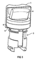
- the protective cap 1 is over with its area 5 the collar 6 of the rotary switch 3 slipped, with which the above Tightness requirements are met according to the task.
Landscapes
- Rotary Switch, Piano Key Switch, And Lever Switch (AREA)
- Switch Cases, Indication, And Locking (AREA)
- Tumbler Switches (AREA)
- Apparatus For Radiation Diagnosis (AREA)
- Surgical Instruments (AREA)
- Light Receiving Elements (AREA)
Abstract
Description
- FIG 1
- eine erfindungsgemäße Schutzkappe in Draufsicht,
- FIG 2
- eine Unteransicht der Schutzkappe mit dem durch sie gebildeten Innenraum und
- FIG 3
- eine Schnittansicht einer über einen Drehschalter gestülpten Schutzkappe.
Claims (2)
- Schutzkappe (1) aus elastischem Material für ein Schaltgerät (3) mit drehbarer Handhabe (4), dadurch gekennzeichnet, daß die Schutzkappe (1) einen inneren Freiraum der Gestalt aufweist, daß die Handhabe (4) in dem bei ihrer Betätigung eingenommenen Raum ohne Rückstellungsdrehmoment durch die Schutzkappe (1) frei beweglich ist.
- Schutzkappe nach Anspruch 1, dadurch gekennzeichnet, daß das Schaltgerät ein Drehschalter (3) ist, der einen Bund (6) aufweist, und daß die Schutzkappe (1) einen über den Bund (6) stülpbaren Bereich (5) aufweist.
Applications Claiming Priority (2)
| Application Number | Priority Date | Filing Date | Title |
|---|---|---|---|
| DE29811828U | 1998-07-02 | ||
| DE29811828U DE29811828U1 (de) | 1998-07-02 | 1998-07-02 | Schutzkappe |
Publications (3)
| Publication Number | Publication Date |
|---|---|
| EP0969490A2 true EP0969490A2 (de) | 2000-01-05 |
| EP0969490A3 EP0969490A3 (de) | 2000-07-05 |
| EP0969490B1 EP0969490B1 (de) | 2006-11-22 |
Family
ID=8059358
Family Applications (1)
| Application Number | Title | Priority Date | Filing Date |
|---|---|---|---|
| EP19990112043 Expired - Lifetime EP0969490B1 (de) | 1998-07-02 | 1999-06-22 | Schutzkappe |
Country Status (2)
| Country | Link |
|---|---|
| EP (1) | EP0969490B1 (de) |
| DE (2) | DE29811828U1 (de) |
Family Cites Families (8)
| Publication number | Priority date | Publication date | Assignee | Title |
|---|---|---|---|---|
| CH223140A (de) * | 1940-12-21 | 1942-08-31 | Licentia Gmbh | Anordnung an einem wettersicheren Gehäuse zur Betätigung von innerhalb desselben angeordneten Schaltgliedern. |
| US2457472A (en) | 1944-05-15 | 1948-12-28 | Weatherhead Co | Packless globe valve |
| DE818891C (de) | 1950-03-03 | 1951-10-29 | Continental Gummi Werke Ag | Federungskoerper |
| US3487186A (en) * | 1965-03-18 | 1969-12-30 | Metex Corp | Shielded resilient boot for electric switches |
| US3668938A (en) | 1971-03-01 | 1972-06-13 | Apm Corp | Hermetically sealing boot with actuator for thumb wheel type switches |
| US3928742A (en) | 1974-07-12 | 1975-12-23 | Rule Industries | Fluid-tight flexible cover |
| US4823397A (en) * | 1988-01-29 | 1989-04-18 | Southern Marine Research, Inc. | Transceiver with moisture resistant cover for thumbwheels and the like |
| DE29517641U1 (de) | 1995-11-07 | 1996-01-04 | Siemens AG, 80333 München | Gegenstand mit folienartigem Schutz, insbesondere Installationsgerät |
-
1998
- 1998-07-02 DE DE29811828U patent/DE29811828U1/de not_active Expired - Lifetime
-
1999
- 1999-06-22 EP EP19990112043 patent/EP0969490B1/de not_active Expired - Lifetime
- 1999-06-22 DE DE59913991T patent/DE59913991D1/de not_active Expired - Lifetime
Non-Patent Citations (1)
| Title |
|---|
| None |
Also Published As
| Publication number | Publication date |
|---|---|
| EP0969490B1 (de) | 2006-11-22 |
| DE29811828U1 (de) | 1998-09-03 |
| DE59913991D1 (de) | 2007-01-04 |
| EP0969490A3 (de) | 2000-07-05 |
Similar Documents
| Publication | Publication Date | Title |
|---|---|---|
| DE3222237C2 (de) | Abgedichteter Kippschalter | |
| DE3122899C2 (de) | Temperaturschalter | |
| EP0623942A1 (de) | Codiervorrichtung | |
| DE2617186B2 (de) | Elektrischer Schalter, insbesondere in Dual-inline-Ausführung | |
| EP0011323A1 (de) | Druckknopf für Tastschalter | |
| DE102016117783B4 (de) | Elektrischer Schalter | |
| DE2158629A1 (de) | Schalter | |
| DE2434272C2 (de) | Elektrischer Schalter | |
| EP0969490A2 (de) | Schutzkappe | |
| WO2005069329A1 (de) | Magnetisch aktivierte kontaktiereinrichtung | |
| DE2103494C3 (de) | Durch einen Druckknopf betätigter Schalter | |
| EP0017814B1 (de) | Einrichtung zum Umstellen einer Umschaltkontaktanordnung | |
| DE1935779B2 (de) | Elektrischer schalter | |
| DE19544467C1 (de) | Elektrische Signalgabeeinrichtung | |
| DE2923019C2 (de) | Hochspannungsschalter | |
| DE3711789C2 (de) | ||
| DE3242024A1 (de) | Digitalschalter | |
| DE694485C (de) | Druckschalter mit einem die festen Kontakte haltenden und die beweglichen Kontakte umhuellenden Isolierkoerper | |
| DE3141181A1 (de) | Schaltgeraet mit einer kulissengefuehrten schaltstange | |
| DE2440550B2 (de) | Schalter für Hilfsstromkreise | |
| DE9103979U1 (de) | Schaltmechanismus für Niederspannungsschaltgeräte | |
| DE1140261B (de) | Brueckenkontaktanordnung fuer elektrische Schaltgeraete | |
| DE1209192B (de) | Elektrischer Schalter | |
| EP0113417A1 (de) | Einrichtung zur Betätigung der Kontaktfedern eines Kontaktfedersatzes | |
| DE1173158B (de) | Befestigung eines elektrischen Schalters mit Betaetigungsglied |
Legal Events
| Date | Code | Title | Description |
|---|---|---|---|
| PUAI | Public reference made under article 153(3) epc to a published international application that has entered the european phase |
Free format text: ORIGINAL CODE: 0009012 |
|
| AK | Designated contracting states |
Kind code of ref document: A2 Designated state(s): DE FR IT |
|
| AX | Request for extension of the european patent |
Free format text: AL;LT;LV;MK;RO;SI |
|
| PUAL | Search report despatched |
Free format text: ORIGINAL CODE: 0009013 |
|
| AK | Designated contracting states |
Kind code of ref document: A3 Designated state(s): AT BE CH CY DE DK ES FI FR GB GR IE IT LI LU MC NL PT SE |
|
| AX | Request for extension of the european patent |
Free format text: AL;LT;LV;MK;RO;SI |
|
| 17P | Request for examination filed |
Effective date: 20000801 |
|
| AKX | Designation fees paid |
Free format text: DE FR IT |
|
| GRAP | Despatch of communication of intention to grant a patent |
Free format text: ORIGINAL CODE: EPIDOSNIGR1 |
|
| GRAS | Grant fee paid |
Free format text: ORIGINAL CODE: EPIDOSNIGR3 |
|
| GRAA | (expected) grant |
Free format text: ORIGINAL CODE: 0009210 |
|
| AK | Designated contracting states |
Kind code of ref document: B1 Designated state(s): DE FR IT |
|
| REF | Corresponds to: |
Ref document number: 59913991 Country of ref document: DE Date of ref document: 20070104 Kind code of ref document: P |
|
| ET | Fr: translation filed | ||
| PLBE | No opposition filed within time limit |
Free format text: ORIGINAL CODE: 0009261 |
|
| STAA | Information on the status of an ep patent application or granted ep patent |
Free format text: STATUS: NO OPPOSITION FILED WITHIN TIME LIMIT |
|
| 26N | No opposition filed |
Effective date: 20070823 |
|
| PGFP | Annual fee paid to national office [announced via postgrant information from national office to epo] |
Ref country code: IT Payment date: 20120626 Year of fee payment: 14 |
|
| PGFP | Annual fee paid to national office [announced via postgrant information from national office to epo] |
Ref country code: DE Payment date: 20120820 Year of fee payment: 14 |
|
| PGFP | Annual fee paid to national office [announced via postgrant information from national office to epo] |
Ref country code: FR Payment date: 20130703 Year of fee payment: 15 |
|
| REG | Reference to a national code |
Ref country code: DE Ref legal event code: R119 Ref document number: 59913991 Country of ref document: DE Effective date: 20140101 |
|
| PG25 | Lapsed in a contracting state [announced via postgrant information from national office to epo] |
Ref country code: DE Free format text: LAPSE BECAUSE OF NON-PAYMENT OF DUE FEES Effective date: 20140101 |
|
| PG25 | Lapsed in a contracting state [announced via postgrant information from national office to epo] |
Ref country code: IT Free format text: LAPSE BECAUSE OF NON-PAYMENT OF DUE FEES Effective date: 20130622 |
|
| REG | Reference to a national code |
Ref country code: FR Ref legal event code: ST Effective date: 20150227 |
|
| PG25 | Lapsed in a contracting state [announced via postgrant information from national office to epo] |
Ref country code: FR Free format text: LAPSE BECAUSE OF NON-PAYMENT OF DUE FEES Effective date: 20140630 |