EP0967445A2 - Klimaanlage mit Luftumwälzung mit geringem Druckverlust - Google Patents
Klimaanlage mit Luftumwälzung mit geringem Druckverlust Download PDFInfo
- Publication number
- EP0967445A2 EP0967445A2 EP99110807A EP99110807A EP0967445A2 EP 0967445 A2 EP0967445 A2 EP 0967445A2 EP 99110807 A EP99110807 A EP 99110807A EP 99110807 A EP99110807 A EP 99110807A EP 0967445 A2 EP0967445 A2 EP 0967445A2
- Authority
- EP
- European Patent Office
- Prior art keywords
- air
- cooling
- section
- temperature
- air conditioning
- Prior art date
- Legal status (The legal status is an assumption and is not a legal conclusion. Google has not performed a legal analysis and makes no representation as to the accuracy of the status listed.)
- Withdrawn
Links
- 238000004378 air conditioning Methods 0.000 title claims abstract description 181
- 238000001816 cooling Methods 0.000 claims abstract description 255
- 238000004140 cleaning Methods 0.000 claims abstract description 31
- 238000000034 method Methods 0.000 claims description 25
- 230000001143 conditioned effect Effects 0.000 claims description 4
- 238000007796 conventional method Methods 0.000 description 12
- 238000004519 manufacturing process Methods 0.000 description 7
- 239000004065 semiconductor Substances 0.000 description 6
- 239000000428 dust Substances 0.000 description 4
- 239000000203 mixture Substances 0.000 description 4
- 230000003068 static effect Effects 0.000 description 4
- 230000002950 deficient Effects 0.000 description 3
- 230000005540 biological transmission Effects 0.000 description 1
- 238000007664 blowing Methods 0.000 description 1
- 230000005484 gravity Effects 0.000 description 1
- 238000010438 heat treatment Methods 0.000 description 1
- 230000009545 invasion Effects 0.000 description 1
- 238000003754 machining Methods 0.000 description 1
- 239000000463 material Substances 0.000 description 1
- 238000011282 treatment Methods 0.000 description 1
Images

Classifications
-
- F—MECHANICAL ENGINEERING; LIGHTING; HEATING; WEAPONS; BLASTING
- F24—HEATING; RANGES; VENTILATING
- F24F—AIR-CONDITIONING; AIR-HUMIDIFICATION; VENTILATION; USE OF AIR CURRENTS FOR SCREENING
- F24F11/00—Control or safety arrangements
- F24F11/30—Control or safety arrangements for purposes related to the operation of the system, e.g. for safety or monitoring
- F24F11/46—Improving electric energy efficiency or saving
-
- F—MECHANICAL ENGINEERING; LIGHTING; HEATING; WEAPONS; BLASTING
- F24—HEATING; RANGES; VENTILATING
- F24F—AIR-CONDITIONING; AIR-HUMIDIFICATION; VENTILATION; USE OF AIR CURRENTS FOR SCREENING
- F24F11/00—Control or safety arrangements
- F24F11/30—Control or safety arrangements for purposes related to the operation of the system, e.g. for safety or monitoring
- F24F11/49—Control or safety arrangements for purposes related to the operation of the system, e.g. for safety or monitoring ensuring correct operation, e.g. by trial operation or configuration checks
-
- F—MECHANICAL ENGINEERING; LIGHTING; HEATING; WEAPONS; BLASTING
- F24—HEATING; RANGES; VENTILATING
- F24F—AIR-CONDITIONING; AIR-HUMIDIFICATION; VENTILATION; USE OF AIR CURRENTS FOR SCREENING
- F24F11/00—Control or safety arrangements
- F24F11/62—Control or safety arrangements characterised by the type of control or by internal processing, e.g. using fuzzy logic, adaptive control or estimation of values
- F24F11/63—Electronic processing
-
- F—MECHANICAL ENGINEERING; LIGHTING; HEATING; WEAPONS; BLASTING
- F24—HEATING; RANGES; VENTILATING
- F24F—AIR-CONDITIONING; AIR-HUMIDIFICATION; VENTILATION; USE OF AIR CURRENTS FOR SCREENING
- F24F11/00—Control or safety arrangements
- F24F11/70—Control systems characterised by their outputs; Constructional details thereof
- F24F11/72—Control systems characterised by their outputs; Constructional details thereof for controlling the supply of treated air, e.g. its pressure
- F24F11/74—Control systems characterised by their outputs; Constructional details thereof for controlling the supply of treated air, e.g. its pressure for controlling air flow rate or air velocity
- F24F11/76—Control systems characterised by their outputs; Constructional details thereof for controlling the supply of treated air, e.g. its pressure for controlling air flow rate or air velocity by means responsive to temperature, e.g. bimetal springs
-
- F—MECHANICAL ENGINEERING; LIGHTING; HEATING; WEAPONS; BLASTING
- F24—HEATING; RANGES; VENTILATING
- F24F—AIR-CONDITIONING; AIR-HUMIDIFICATION; VENTILATION; USE OF AIR CURRENTS FOR SCREENING
- F24F11/00—Control or safety arrangements
- F24F11/70—Control systems characterised by their outputs; Constructional details thereof
- F24F11/80—Control systems characterised by their outputs; Constructional details thereof for controlling the temperature of the supplied air
-
- F—MECHANICAL ENGINEERING; LIGHTING; HEATING; WEAPONS; BLASTING
- F24—HEATING; RANGES; VENTILATING
- F24F—AIR-CONDITIONING; AIR-HUMIDIFICATION; VENTILATION; USE OF AIR CURRENTS FOR SCREENING
- F24F3/00—Air-conditioning systems in which conditioned primary air is supplied from one or more central stations to distributing units in the rooms or spaces where it may receive secondary treatment; Apparatus specially designed for such systems
- F24F3/12—Air-conditioning systems in which conditioned primary air is supplied from one or more central stations to distributing units in the rooms or spaces where it may receive secondary treatment; Apparatus specially designed for such systems characterised by the treatment of the air otherwise than by heating and cooling
- F24F3/16—Air-conditioning systems in which conditioned primary air is supplied from one or more central stations to distributing units in the rooms or spaces where it may receive secondary treatment; Apparatus specially designed for such systems characterised by the treatment of the air otherwise than by heating and cooling by purification, e.g. by filtering; by sterilisation; by ozonisation
- F24F3/167—Clean rooms, i.e. enclosed spaces in which a uniform flow of filtered air is distributed
-
- F—MECHANICAL ENGINEERING; LIGHTING; HEATING; WEAPONS; BLASTING
- F24—HEATING; RANGES; VENTILATING
- F24F—AIR-CONDITIONING; AIR-HUMIDIFICATION; VENTILATION; USE OF AIR CURRENTS FOR SCREENING
- F24F8/00—Treatment, e.g. purification, of air supplied to human living or working spaces otherwise than by heating, cooling, humidifying or drying
- F24F8/10—Treatment, e.g. purification, of air supplied to human living or working spaces otherwise than by heating, cooling, humidifying or drying by separation, e.g. by filtering
-
- F—MECHANICAL ENGINEERING; LIGHTING; HEATING; WEAPONS; BLASTING
- F24—HEATING; RANGES; VENTILATING
- F24F—AIR-CONDITIONING; AIR-HUMIDIFICATION; VENTILATION; USE OF AIR CURRENTS FOR SCREENING
- F24F2110/00—Control inputs relating to air properties
- F24F2110/10—Temperature
-
- F—MECHANICAL ENGINEERING; LIGHTING; HEATING; WEAPONS; BLASTING
- F24—HEATING; RANGES; VENTILATING
- F24F—AIR-CONDITIONING; AIR-HUMIDIFICATION; VENTILATION; USE OF AIR CURRENTS FOR SCREENING
- F24F2110/00—Control inputs relating to air properties
- F24F2110/20—Humidity
-
- F—MECHANICAL ENGINEERING; LIGHTING; HEATING; WEAPONS; BLASTING
- F24—HEATING; RANGES; VENTILATING
- F24F—AIR-CONDITIONING; AIR-HUMIDIFICATION; VENTILATION; USE OF AIR CURRENTS FOR SCREENING
- F24F2110/00—Control inputs relating to air properties
- F24F2110/40—Pressure, e.g. wind pressure
Definitions
- the present invention relates to an air conditioning apparatus and an air conditioning method for reducing a pressure loss of circulation air to reduce electric power consumption for circulating circulation air in the air conditioning apparatus.
- a method for manufacturing a semiconductor device needs a process of using a hyperfine machining treatments. Associated with this process, dust existing in manufacture space for the semiconductor device invades the semiconductor device at a process of manufacturing the semiconductor device, and this invasion may cause the semiconductor device to be defective. Also, the change of temperature or humidity in the manufacture space may cause slight curvature or distortion to be incurred in a material used for the manufacture, which thereby may cause the semiconductor device to be defective. For dropping the rate of the defective device, it is necessary to reduce the quantity of the dust existing in the manufacture space and also necessary to keep the temperature and the humidity in the manufacture space constant. In response to above-mentioned request, the space is developed which is referred to as a clean room where the dust is reduced as much as possible and the temperature and the humidity are kept constant.
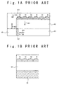
- Figs. 1A and 1B show a conventional clean room air conditioning apparatus using a FFU (Fan Filter Unit).
- Fig. 1A is a front section view showing this conventional clean room air conditioning apparatus.
- Fig. 1B is a side section view showing this conventional clean room air conditioning apparatus.
- the conventional clean room air conditioning apparatus using the FFU is provided with FFUs 41, a clean room interior 42, an under-floor portion 43, a cooling coil 44, and a return shaft 45.
- FFUs 41 are set on a top surface of a clean room interior 42.
- a cooling coil 44 is set in an under-floor portion 43 of the clean room.
- a return shaft 45 is set outside the clean room for controlling a temperature of air passing through the cooling coil 44.
- the air is circulated in an order of an air flow 401, an air flow 402, an air flow 403 and an air flow 404 shown in Fig. 1A.
- air cleaned by the FFUs 41 is perfectly passed through the clean room interior 42, the under-floor portion 43 and the cooling coil 44.
- the air is cooled when the air passes through the cooling coil 44.
- the temperature of the cooled air is controlled by the return shaft 45 and returned to the FFUs 41.
- the air conditioning apparatus has a problem that a pressure loss of the circulation air in the clean room is large.
- a pressure loss of the circulation air in the clean room is large.
- the circulation air perfectly passes through the cooling coil which has the large pressure loss, when the quantity of circulation wind is determined not for cooling heat generated in the clean room but for keeping a room clean at a certain degree.
- JP-A-Heisei 4-103937 describes "Method for Controlling Wind Quantity of Clean Room".
- a fan motor of FFU is composed of a single-phase motor in which rotation speeds can be changed in a plurality of stages by an operation of tap changing.
- An operational terminal unit for carrying out an ON-OFF operation and a tap changing operation of the single-phase motor is mounted for each FFU.
- a transmission line is laid for transmitting an operational command to each operational terminal device.
- the drive number of FFUs and the blown-out wind speeds from the FFUs are controlled through the remote operations of those operational terminal devices.
- JP-A-Heisei 7-4724 describes "Method for Controlling And Saving Energy of Air Conditioning System".
- This conventional technique has the following feature. Air inside a room is sucked into an air conditioning apparatus through an air filter by a fan motor. A temperature of the sucked air is measured by an sensor set at a sucked air unit in the air conditioning apparatus. The air sucked into the air conditioning apparatus is cooled by a cooling unit, and again heated by a re-heating unit, and humidified by a humidifier, and then blown from the air conditioning apparatus. The temperature and the humidity of the blown air are measured by an sensor set outside the air conditioning apparatus.
- the wind quantity is controlled in accordance with a present wind rate and a temperature difference measured by the sensor set at a sucked air unit and the sensor set outside the air conditioning apparatus.
- the cooling quantity is controlled in accordance with the controlled wind quantity.
- an open degree of a bypass damper for bypassing the air passed through the cooling unit is controlled in accordance with the humidity measured by the sensor set outside the air conditioning apparatus.
- JP-A-Heisei 9-159239 describes "Clean Room”.
- This conventional technique has the following feature. This is provided with a plate-shaped member with many holes set in the vicinity of a blowing port of FFU and an air releasing unit which is spaced away from the FFU and set substantially opposite to the FFU. An opening rate adjusted on the basis of the plate-shaped hole with the many holes is different depending on the set or non-set position of the FFU.
- JP-A-Heisei 9-287791 describes "Filter Unit And Clean Room Having Chamber".
- This conventional technique has the following feature. A plurality of FFUs are set removed, and a floor surface having an opening is placed in the clean room. The FFU is covered with a small chamber whose bottom surface is open and which is box-shaped and used for ceiling suck. An air intake is created around an air outtake of the FFU. A fan of the FFU is used to carry out the air blowout from the FFU and the air suck to the small chamber at the same time. It is possible to adjust a valve mounted at the air intake on a top surface of the small chamber to thereby adjust the balance between the quantity of the air suck from the ceiling and the quantity of the air suck to the small chamber.
- JP-A-Heisei 8-152170 describes "Structure of Clean Room".
- This conventional technique has the following feature. At first, a ceiling surface is made into an air filter surface provided with a plurality of air filters. Then, a clean room is created in which air is passed along a floor surface. Duct space for air circulation is disposed in portion outside the clean room. A cooling coil having a fan on a rear side thereof is set on a circulation path of the portion outside the clean room.
- the present invention has been made to solve the above-explained problems.
- an object of the present invention is to provide an air conditioning apparatus and an air conditioning method which can reduce electric power consumption for circulating circulation air by reducing a pressure loss given to circulation air, when the quantity of circulation air is determined not for cooling heat generated in the clean room but for keeping a room clean.
- an air conditioning apparatus includes a clean room, an air cleaning section, a cooling section and an air mixing section.
- the air cleaning section cleans air to supply to the clean room as cleaned air.
- the cooling section includes a plurality of cooling units and a plurality of non-cooling units. A plurality of cooling units cool air from the clean room to send out as cooled air. A plurality of non-cooling units sends out as non-cooled air from the clean room without cooling air.
- Each of the quantity of the cooled air and the non-cooled air is determined to compensate an amount of heat generated in the air conditioning apparatus and to reduce a pressure loss given to the air passing through the cooling section to a substantial minimum.
- the air mixing section mixes the cooled air and the non-cooled air to supply to the air cleaning section.
- the cleaned air is circulated through the clean room, the cooling section and the air mixing section to the air cleaning section.
- the air cleaning section may give a first pressure to the cleaned air to circulate the cleaned air through the clean room, the non-cooling unit in the cooling section and the air mixing section to the air cleaning section.
- the cooling section may give a second pressure to the cooled air to compensate the pressure loss given to the air passing through the cooling unit.
- the air cleaning section may include a fan filter unit.
- the fan filter unit including a filter and a fan. The fan sucks air and sends the sucked air to the filter. The filter cleans the air sent by the fan.
- the cooling unit may include a cooling equipment and a fan motor.
- the cooling equipment cools the cooled air.
- the fan motor gives a fan pressure to the cooled air. The fan pressure compensates for a pressure loss given the cooled air passing through the cooling equipment.
- the fan motor may further include a temperature measuring section and a temperature controller.
- the temperature measuring section measures a temperature of circulation air circulated in the air conditioning apparatus.
- the temperature controller stores a pre-determined temperature and controls a quantity of the circulation air passing through the cooling equipment based on a comparison with the measured temperature and the pre-determined temperature.
- the air conditioning apparatus may further include a temperature measuring section and a temperature controller.
- the temperature measuring section measures a temperature of circulation air circulated in the air conditioning apparatus.
- the temperature controller stores a pre-determined temperature and controls a number of the fan motors driving based on a comparison with the measured temperature and the pre-determined temperature.
- At least one of the cooling unit may include an air conditioning unit.
- the air conditioning unit adjusts a temperature and a humidity of the air passing through the air conditioning unit.
- the cooling section may divide the air passing through the cooling section into the cooled air, non-cooled air and a conditioned air passing through the air conditioning unit to compensate an amount of heat generated in the air conditioning apparatus and to reduce the pressure loss given to the air passing through the cooling section to a substantial minimum.
- the air conditioning apparatus may further include a temperature humidity measuring section and a temperature humidity controller.
- the temperature humidity measuring section measures a temperature and a measured humidity of circulation air.
- the temperature humidity controller stores a pre-determined temperature and a pre-determined humidity of the circulation air and controls a quantity of the cooled air and the conditioned air based on a comparison with the measured temperature and the pre-determined temperature and another comparison with the measured humidity and the pre-determined humidity.
- the air conditioning apparatus may further include a temperature humidity measuring section and a temperature humidity controller.
- the temperature humidity measuring section measures a temperature and a humidity of the circulation air.
- the temperature humidity controller stores a pre-determined temperature and a pre-determined humidity of the circulation air and controls the numbers of the air controlling units to be driven and the cooling units to be driven, based on a comparison with the measured temperature and the pre-determined temperature and another comparison with the measured humidity and the pre-determined humidity.
- an arrangement of the cooling units, the non-cooling units and the air conditioning units may be changeable in the cooling section.
- an arrangement of the cooling units and the bypass units may be changeable in the cooling section.
- an air conditioning method of an air conditioning apparatus includes steps of (a), (b) and (c).
- the air conditioning apparatus includes a clean room, an air cleaning section and an air mixing section.
- the air cleaning section cleans air passing through the air cleaning section.
- the cooling section includes a plurality of cooling units of cooling air passing through the plurality of cooling units and a plurality of non-cooling units without cooling air passing through the plurality of non-cooling units.
- the air mixing section mixes the air passing through the plurality of cooling units and the air passing through the plurality of non-cooling units.
- the step of (a) is a step of giving a pressure to circulation air circulated in the air conditioning apparatus to circulate the circulation air through the clean room, the non-cooling unit in the cooling section and the air mixing section to the air cleaning section.
- the step of (b) is a step of dividing the circulation air passing through the cooling section into a first air passing through the plurality of cooling units and a second air passing through the plurality of non-cooling units to cool the first air based on an amount of heat generated in the air conditioning apparatus and to reduce a pressure loss given to the circulation air passing through the cooling section to a substantial minimum.
- the step of (c) is a step of giving to the first air a pressure substantially equal to a pressure loss given to the first air passing through the cooling unit.
- the step of (b) may include steps of (d), (e) and (f).
- the step of (d) is a step of determining a pre-determined temperature.
- the step of (e) is a step of measuring a temperature of the circulation air before passing through the cooling section.
- the step of (f) is a step of dividing the circulation air passing through the cooling section into a quantity of the first air passing through the plurality of cooling units and a quantity of a second air passing through the plurality of non-cooling units based on a comparison with the measured temperature and the pre-determined temperature to reduce a pressure loss given to the air passing through the cooling section to a substantial minimum.
- the step of (c) may include a step of (g) controlling the quantity of the first air based on the result of the step of (f).
- a part of the cooling units may include air conditioning units of changing a temperature and a humidity of an air passing through the air conditioning units.
- the step of (b) includes a step of (h).
- the step of (h) is a step of dividing the circulation air passing through the cooling section into a first air passing through the plurality of cooling units, a second air passing through the plurality of non-cooling units and a third air passing the air conditioning units to cool the first air and the third air in response to an amount of heat generated in the air conditioning apparatus and to reduce the pressure loss given to the circulation air passing through the cooling section to a substantially minimum.
- the air conditioning method may further includes a step of (I).
- the step of (i) is a step of giving to the third air a pressure substantially equal to the pressure loss given to the third air passing through the air conditioning units.
- the air conditioning method may further includes steps of (j) and (k).
- the step of (j) is a step of determining a pre-determined temperature and a pre-determined humidity.
- the step of (k) is a step of measuring a temperature and a humidity of the circulation air before passing through the cooling section.
- the step of (h) may include a step of (l).
- the step of (l) is a step of dividing the circulation air passing through the cooling section into a first air passing through the plurality of cooling units, a second air passing through the plurality of non-cooling units and a third air passing the air conditioning units to cool the first air and the third air and to adjust a humidity of the third air based on a comparison with the measured temperature and the pre-determined temperature and another comparison with the measured humidity and the pre-determined humidity to reduce a pressure loss given to the circulation air passing through the cooling section to a substantial minimum.
- the step of (c) may further include a step of (m).
- the step of (m) is a step of controlling the quantity of the first air based on the step of (l).
- the step of (i) may further include a step of (n).
- the step of (n) is a step of controlling the quantity of the third air based on the step of (l).
- an air conditioning apparatus of a clean room includes an air cleaning portion, a cooling portion, an air mixing portion, an air circulating section.
- the air cleaning portion cleans air passing through the air cleaning section.
- the cooling portion includes a plurality of cooling units of cooling air passing through the cooling units; and a plurality of non-cooling units without cooling air passing through the non-cooling units.
- the air circulating section circulates a first air cleaned by the air cleaning section, through the clean room, the cooling portion and the air mixing portion to the air cleaning portion.
- the cooling section includes a dividing section and a cooling section.
- the dividing section divides the first air passing through the cooling section into a second air passing through the plurality of cooling units and a third air passing through the plurality of non-cooling unit.
- the cooling section cools the second air in the plurality of cooling units.
- the air mixing portion includes a mixing section mixing the second air cooled by the cooling section and the third air.
- each of the plurality of cooling units may include an cooling apparatus and an wind supplying apparatus supplying the second air to the cooling apparatus.
- the wind supplying apparatus may include a storing area, a first temperature measuring section and a controller.
- the storing area stores a pre-determined temperature.
- the first temperature measuring section measures a temperature of a circulation air circulated in the air conditioning apparatus.
- the controller controls a quantity of the second air supplied to the cooling apparatus based on a comparison with the measured temperature and the pre-determined temperature.
- the cooling section may further include a plurality of air conditioning units and a dividing section.
- the dividing section divides the first air passing through the cooling section into a second air passing through the plurality of cooling units, a third air passing through the plurality of non-cooling units and a fourth air passing through the plurality of air adjusting units.
- the air conditioning unit may further include a storing area, a second temperature humidity measuring section and an adjusting section.
- the storing area stores a pre-determined temperature and a pre-determined humidity.
- the second temperature humidity measuring section measures a temperature and a measured of the circulation air.
- the adjusting section adjusts a temperature and a humidity of the fourth air passing through the air conditioning unit based on a comparison with the measured temperature and the pre-determined temperature and another comparison with the measured humidity and the pre-determined humidity.
- the mixing section may mix the second air, the third air and the fourth air passing through the cooling section.
- the various air conditioning apparatuses and air conditioning methods of the present invention will be adapted to an air conditioning apparatus of a clean room using FFUs (Fan Filter Units).
- FFUs Fluor Filter Units
- the air conditioning apparatus of the present invention is adapted when the quantity of air circulated in the air conditioning apparatus is determined not for keeping cool from an amount of heat generated in the clean room but for keeping the clean room clean.
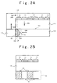
- Figs. 2A, 2B and 2C show the air conditioning apparatus according to the first embodiment of the present invention.
- Fig. 2A is a section view of the air conditioning apparatus according to the first embodiment of the present invention.
- Fig. 2B is a section view taken on the line A-A' of Fig. 2A.
- Fig. 2B mainly shows a structure of a cooling section.
- Fig. 2C is a section view showing an arrangement of a cooling unit constituting a part of the cooling section.
- FFUs 11 are set on a ceiling of a clean room interior 12.
- the clean room interior 12 and an under-floor portion 13 are partitioned with an access floor 121 as a boundary.
- a cooling section 14 is set in the under-floor portion 13.
- a return shaft 17 is set in a portion outside the clean room.
- the cooling section 14 is constituted by the combination of at least one of cooling units 15 and at least one of bypass units 16 shown in Fig. 2B.
- a cooling unit 15 is provided with a fan 151 and a cooling coil 152 shown in Fig. 2C.
- the FFU 11 has a function of giving the pressure to the circulation air for compensating a pressure loss given to the circulation air which is passed through the bypass unit 16 in the cooling section 14 and to the FFUs 11.
- the access floor 121 has a plurality of holes through which the circulation air can pass.
- the circulation air passing through the cooling section 14 is divided into a part of the circulation air passing through the cooling unit 15 and the remaining circulation air passing through the bypass unit 16.
- the cooling coil 152 in the cooling unit 15 cools the part of the circulation air passing through the cooling unit 15.
- the bypass unit 16 has a function that the remaining circulation air can be merely passing through the bypass unit 16.
- the pressure loss of the cooling coil 152 is larger than that of the bypass unit 16.
- the fan 151 in the cooling unit 15 has a function of giving the pressure substantially equal to the pressure loss of the cooling coil 152 to the part of the circulation air.
- the return shaft 17 has a function of mixing the part of the circulation air passing through the cooling unit 15 in the cooling section 14 and the remaining circulation air passed through the bypass unit 16 in the cooling section 14. And the return shaft 17 sends the mixture circulation air to the FFUs 11.
- the circulation air circulates in an order of an air flow 201, an air flow 202, an air flow 203 and an air flow 204 shown in Fig. 2A.
- the circulation air blown by the FFU 11 set on the ceiling of the clean room interior 12 is passed through the clean room interior 12 and the access floor 121 and then entered in the under-floor portion 13. Then, the circulation air entered in the under-floor portion 13 is entered in the cooling section 14. A part of the circulation air entered in the cooling section 14 passes through the cooling unit 15, and the remaining circulation air passes through the bypass unit 16. Only the circulation air passing through the cooling unit 15 is cooled at this time. The part of the circulation air passing through the cooling unit 15 and the remaining circulation air passing through the bypass unit 16 is mixed by the return shaft 17, and then the mixture circulation air is returned to the FFUs 11.
- a circulation route of the circulation air in the air conditioning apparatus is as follows.
- the circulation air blown by the FFUs 11 set on the ceiling of the clean room interior 12 passes through the clean room interior 12 and the access floor 121 to the under-floor portion 13.
- the circulation air entered in the under-floor portion 13 is entered in the cooling section 14.
- a part of the circulation air passes through the cooling unit 15 and the remaining circulation air passes through the bypass unit 16.
- the part of the circulation air passing through the cooling unit 15 and the remaining circulation air passing through the bypass unit 16 are mixed by the return shaft 17, and the mixture circulation air is returned to the FFUs 11.
- the circulation route of the circulation air in the conventional air conditioning apparatus shown in Figs. 1A and 1B will be described.
- the circulation air blown by the FFUs 41 set on the ceiling of the clean room interior 42 passes through the clean room interior 42 and the access floor to the under-floor portion 43.
- the circulation air entered in the under-floor portion 43 passes through the cooling coil 44 to the return shaft 45, and then is returned to the FFUs 11.
- the circulation air entered in the under-floor portion 43 passes perfectly through the cooling coil 44 to the return shaft 45.
- a filter pass static pressure adds to the circulation air passing through the filter in the FFU. Moreover, the pressure losses are given to the circulation air when the circulation air passes through the access floor, the under-floor portion, the bypass unit, the cooling coil, and the return shaft, respectively.
- the circulation air is circulated from the FFU through the access floor, the under-floor portion, the cooling coil and the return shaft.
- the sum of the filter pass static pressure and the pressure losses of the access floor, the under-floor portion, the cooling coil, and the return shaft respectively is given to the circulation air for circulating the circulation air in the conventional air conditioning apparatus.
- the first embodiment in the air conditioning apparatus of the present invention has two air circulation paths.
- the circulation air is circulated from the FFUs through the access floor, the under-floor portion, the cooling coil and the return shaft.
- the second air circulation path the circulation air is circulated from the FFUs through the access floor, the under-floor portion, the bypass unit and the return shaft.
- the total pressure of the filter pass static pressure and the pressure losses of the access floor, the under-floor portion, the cooling coil and the return shaft respectively is given to the circulation air for circulating the circulation air in the invented air conditioning apparatus.
- the total presure of the filter pass static pressure and the pressure losses of the access floor, the under-floor portion, the bypass unit and the return shaft respectively is given to the circulation air for circulating the circulation air in the invented air conditioning apparatus.
- the circulation air is perfectly passed through the cooling coil.
- the quantity of the circulation air passed through the cooling coil is 1,000,000 m 3 /h
- the quantity of the circulation air passed through the bypass unit is 2,000,000 m 3 /h.
- the air conditioning apparatus according to the first embodiment of the present invention can improve the efficiency of the electric power consumption by about 10 per cent, as compared with that according to the conventional technique.
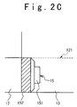
- Figs. 3A, 3B and 3C show the air conditioning apparatus according to the second embodiment of the present invention.
- Fig. 3A is a section view of the air conditioning apparatus according to the second embodiment of the present invention.
- Fig. 3B is a section view taken on the line B-B' of Fig. 3A.
- Fig. 3B mainly shows the structure of a cooling section.
- Fig. 3C is a section view showing an arrangement of a cooling unit constituting a part of the cooling section.
- FFUs 21 are set on a ceiling of a clean room interior 22.
- the clean room interior 22 and an under-floor portion 23 are partitioned with an access floor 221 as a boundary.
- a cooling section 24 is set in the under-floor portion 23.
- a return shaft 27 is set in a portion outside the clean room.
- the cooling section 24 is constituted by the combination of at least one of cooling units 25 and at least one of bypass units 26.
- the cooling unit 25 consists of a wind quantity changeable unit 251 and a cooling coil 252 shown in Fig. 3C.
- the wind quantity changeable unit 251 is linked to a temperature controller 242.
- This wind quantity changeable unit 251 has a function of giving a wind pressure for compensating a pressure loss of the cooling coil 252.
- it is provided with a temperature measuring section 241 and the temperature controller 242 in the cooling unit 25.
- the temperature measuring section 241 measures a temperature of the circulation air.
- the temperature controller 242 controls the quantity of the wind which the wind quantity changeable unit 251 sends to the cooling coil 252 according to the temperature measured by the temperature measuring section 241.
- the temperature measuring section 241 measures a temperature of the circulation air given an amount of heat generated in the clean room. It is desirable that the temperature measuring section 241 is set at the under-floor portion 23 of the clean room or the access floor 221. Also, the temperature measuring section 241 may be set at the wind quantity changeable unit 251 of the cooling section 24.
- the circulation air circulates in an order of an air flow 201, an air flow 202, an air flow 203 and an air flow 204, shown in Fig. 3A.
- the air conditioning apparatus In the air conditioning apparatus according to the second embodiment of the present invention, it is characterized that it is provided with a temperature measuring section 241 and the temperature controller 242 in the cooling unit 25, compared with that according to the first embodiment of the present invention.
- the temperature measuring section 241 measures a temperature of the circulation air.
- the temperature controller 242 controls the quantity of the air which the wind quantity changeable unit 251 sends to the cooling coil 252 based on the temperature measured by the temperature measuring section 241.
- the quantity of air circulated in the air conditioning apparatus is decided not for keeping cool from an amount of heat generated in the clean room but for keeping the clean room clean.
- the temperature controller 242 controls the quantity of the air blown into the cooling coil 252 by the wind quantity changeable unit 251 to remove heat substantially equal to an amount of heat generated in the clean room.
- the quantity of the air passing through the cooling coil 252. it is possible to compensate an amount of heat generated in the clean room to reduce the pressure loss given to the circulation air to a substantial minimum. Hence, it is possible to improve the efficiency of the electric power consumption necessary for circulating the air circulation.
- the temperature controller 242 has a pre-determined temperature in the circulation air.
- the temperature controller 242 controls the quantity of air blown into the cooling coil 252 by the wind quantity changeable unit 251 based on a comparison with the pre-determined temperature and the temperature measured by the temperature measuring section 241.
- the temperature controller 242 may control the quantity of the air in each wind quantity changeable unit 251 and also control the number of the wind quantity changeable units 251 which drive.
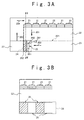
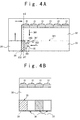
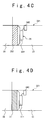
- Figs. 4A, 4B and 4C show the air conditioning apparatus according to the third embodiment of the present invention.
- Fig. 4A is a section view of the air conditioning apparatus according to the third embodiment of the present invention.
- Fig. 4B is a section view taken on the line C-C' of Fig. 4A.
- Fig. 4B mainly shows the structure of a cooling section.
- Fig. 4C is a section view showing an arrangement of a cooling unit constituting a part of the cooling section.
- Fig. 4D is a section view showing an arrangement of an air conditioning unit constituting a part of the cooling section.
- FFUs 31 are set on a ceiling of a clean room interior 32.
- the clean room interior 32 and an under-floor portion 33 are partitioned with an access floor 321 as a boundary.
- a cooling section 34 is set in the under-floor portion 33.
- a return shaft 38 is set in a portion outside the clean room.
- the cooling section 34 is set by the combination of a cooling unit 35, a bypass unit 36 and an air conditioning unit 37.
- the cooling unit 35 consists of a wind quantity changeable unit 351 and a cooling coil 352 shown in Fig. 4C.
- This wind quantity changeable unit 351 has a function of giving to the air passing through the cooling coil 352 a pressure which is substantially equal to a pressure loss given to the air passing through the cooling coil 352.
- the variable wind quantity unit 351 is linked to a temperature humidity controller 342.
- a wind quantity changeable unit 371 is set in an air conditioning unit 37 shown in Fig. 4D.
- This wind quantity changeable unit 371 has a function of giving to the air passing through the air conditioning unit 37 a pressure which is substantially equal to a pressure loss given to the air passing through the air conditioning unit 37.
- the wind quantity changeable unit 371 is linked to the temperature humidity controller 342.
- the air conditioning apparatus has a temperature humidity measuring section 341, the temperature humidity controller 342 and the wind quantity changeable units 351, 371.
- the temperature humidity measuring section 341 measures a temperature and a humidity of the circulation air in the air conditioning apparatus. According to the temperature and a humidity of the circulation air measured by the temperature humidity measuring section 341, the temperature humidity controller 342 controls the wind quantity changeable unit 351, 371 to adjust the quantity of air blown into the cooling unit 35 and the air adjusting unit 37.
- the circulation air circulates in an order of an air flow 401, an air flow 402, an air flow 403 and an air flow 404 shown in Fig. 4A.
- the air conditioning apparatus further includes the air adjusting unit 37 and the variable wind quantity unit 371 in the cooling unit 34, compared with the air conditioning apparatus according to the second embodiment of the present invention.
- the air conditioning apparatus according to the third embodiment of the present invention includes the temperature humidity measuring section 341 and the temperature humidity controller 342 instead of the temperature measuring section 241 and the temperature controller 242 in the air conditioning apparatus according to the second embodiment of the present invention, respectively.
- the temperature humidity measuring section 341 measures the temperature and the humidity of the circulation air.
- the temperature humidity controller 342 controls the wind quantity changeable unit 351 and the wind quantity changeable unit 371 to adjust the quantity of the air blown into the cooling unit 35 and/or that of the air blown into the air adjusting unit 37, based on the temperature and the humidity measured by the temperature humidity measuring section 341.
- the temperature humidity measuring section 341 measures the temperature and the humidity of the circulation air and the temperature and the humidity are changed in response to the load given in the clean room. It is desirable that the temperature humidity measuring section 341 is set at the under-floor portion 33 of the clean room or the access floor 321. Moreover, the temperature humidity measuring section 341 may be set at the variable wind quantity units 351, 371 in the cooling section 34.
- the quantity of air circulated in the air conditioning apparatus is decided not for keeping cool from an amount of heat generated in the clean room but for keeping the clean room clean.
- the temperature controller 242 controls the quantity of the air blown into the cooling coil 352 and the air conditioning unit 37 to remove the load substantially equal to the load generated in the clean room. It is possible to control each of the quantity of the air passed through the cooling coil 352 and passed through the air conditioning unit 37. Thus, it is possible to compensate a load generated in the clean room to reduce the pressure loss given to the circulation air substantially to a minimum. Hence, it is possible to improve the efficiency of the electric power consumption necessary for circulating the air circulation.
- the temperature humidity controller 342 has a pre-determined temperature and humidity in the circulation air, respectively.
- the temperature humidity controller 342 controls the quantity of air blown into the cooling coil 352 by the wind quantity changeable unit 351 and that blown into the air conditioning unit 37 by the wind quantity changeable unit 371 according to the result of the comparison between the pre-determined temperature and humidity, and the temperature and humidity measured by the temperature measuring section 341, respectively.
- the temperature humidity controller 342 can control the quantity of the wind in each wind quantity changeable unit 351, 371 and also control the number of the wind quantity changeable units 251, 371 which drive.
- the temperature humidity controller 342 controls the operations of the wind quantity changeable unit 351 in the cooling unit 35 and the wind quantity changeable unit 371 set in the air conditioning unit 37 to adjust the quantity of the wind passed through the cooling unit 35 and the quantity of the air passed through the air conditioning unit 37.
- the air conditioning apparatus of the present invention it is possible to arbitrarily determine and change the arrangements of the cooling unit, the bypass unit and the air conditioning unit in the cooling section. Moreover, it is possible to freely change a unit width of the bypass unit. In short, the air conditioning apparatus of the present invention has the feature that the layout in the cooling section is determined freely.
Landscapes
- Engineering & Computer Science (AREA)
- General Engineering & Computer Science (AREA)
- Chemical & Material Sciences (AREA)
- Combustion & Propulsion (AREA)
- Mechanical Engineering (AREA)
- Physics & Mathematics (AREA)
- Signal Processing (AREA)
- Fluid Mechanics (AREA)
- Fuzzy Systems (AREA)
- Mathematical Physics (AREA)
- Air Conditioning Control Device (AREA)
- Ventilation (AREA)
- Central Air Conditioning (AREA)
Applications Claiming Priority (2)
| Application Number | Priority Date | Filing Date | Title |
|---|---|---|---|
| JP10179336A JP3092705B2 (ja) | 1998-06-25 | 1998-06-25 | 空調装置 |
| JP17933698 | 1998-06-25 |
Publications (2)
| Publication Number | Publication Date |
|---|---|
| EP0967445A2 true EP0967445A2 (de) | 1999-12-29 |
| EP0967445A3 EP0967445A3 (de) | 2002-06-05 |
Family
ID=16064066
Family Applications (1)
| Application Number | Title | Priority Date | Filing Date |
|---|---|---|---|
| EP99110807A Withdrawn EP0967445A3 (de) | 1998-06-25 | 1999-06-04 | Klimaanlage mit Luftumwälzung mit geringem Druckverlust |
Country Status (4)
| Country | Link |
|---|---|
| US (1) | US6151903A (de) |
| EP (1) | EP0967445A3 (de) |
| JP (1) | JP3092705B2 (de) |
| KR (1) | KR100355629B1 (de) |
Cited By (1)
| Publication number | Priority date | Publication date | Assignee | Title |
|---|---|---|---|---|
| EP2071248A1 (de) | 2007-12-14 | 2009-06-17 | GE-Hitachi Nuclear Energy Americas LLC | Luftfilterung und -handhabung für den Bewohnbarkeitsbereich eines Atomreaktors |
Families Citing this family (13)
| Publication number | Priority date | Publication date | Assignee | Title |
|---|---|---|---|---|
| EP1258182A4 (de) | 2000-02-18 | 2008-12-17 | Rtkl Associates Inc | Wärmeabführeinrichtung für computergestelle |
| US6557357B2 (en) | 2000-02-18 | 2003-05-06 | Toc Technology, Llc | Computer rack heat extraction device |
| US6412292B2 (en) | 2000-05-09 | 2002-07-02 | Toc Technology, Llc | Computer rack heat extraction device |
| US6574970B2 (en) | 2000-02-18 | 2003-06-10 | Toc Technology, Llc | Computer room air flow method and apparatus |
| US6293115B1 (en) | 2000-04-10 | 2001-09-25 | Delphi Technologies, Inc. | Inlet air mixture control method for a vehicle air conditioning system |
| JP2002147811A (ja) * | 2000-11-08 | 2002-05-22 | Sharp Corp | クリーンルーム |
| JP4038352B2 (ja) * | 2001-08-24 | 2008-01-23 | 株式会社日立産機システム | クリーンルーム |
| DE10350678A1 (de) * | 2003-10-30 | 2005-06-16 | Gebhardt Ventilatoren Gmbh & Co. | Zuluftgerät, insbesondere zur Befestigung an Decken von Reinräumen |
| KR20060056709A (ko) * | 2004-11-22 | 2006-05-25 | 삼성전자주식회사 | 도어 입구에 에어 커튼을 가지는 반도체 제조 장비 |
| US7334938B2 (en) * | 2005-01-03 | 2008-02-26 | Ralph Remsburg | Mold and fungus growth warning apparatus and method |
| US20060199508A1 (en) * | 2005-01-28 | 2006-09-07 | Nair Manu Kumar V | Intensifier |
| US8333517B2 (en) * | 2007-02-05 | 2012-12-18 | Nippon Telegraph And Telephone Corporation | Semiconductor submodule, method for connecting connector and semiconductor submodule, and optical module |
| CN103308436A (zh) * | 2013-05-30 | 2013-09-18 | 苏州华达仪器设备有限公司 | 一种气体检测实验室 |
Citations (5)
| Publication number | Priority date | Publication date | Assignee | Title |
|---|---|---|---|---|
| JPH04103937A (ja) | 1990-08-21 | 1992-04-06 | Takasago Thermal Eng Co Ltd | クリーンルームの風量制御方法 |
| JPH074724A (ja) | 1992-12-22 | 1995-01-10 | Fujitsu Syst Constr Kk | 空調設備の省エネルギー制御方式 |
| JPH08152170A (ja) | 1994-11-25 | 1996-06-11 | Shin Nippon Kucho Kk | クリーンルーム構造 |
| JPH09159239A (ja) | 1995-12-07 | 1997-06-20 | Hitachi Ltd | クリーンルーム |
| JPH09287791A (ja) | 1996-04-23 | 1997-11-04 | Hitachi Plant Eng & Constr Co Ltd | チャンバー付きファンフィルターユニット及びクリーンルーム |
Family Cites Families (6)
| Publication number | Priority date | Publication date | Assignee | Title |
|---|---|---|---|---|
| EP0326726A1 (de) * | 1988-02-02 | 1989-08-09 | Hirayama Setsubi Kabushiki Kaisha | Reinraumanlage und Baueinheit für diese Reinraumanlage |
| JPH02208433A (ja) * | 1989-02-03 | 1990-08-20 | Mitsubishi Electric Corp | クリーンルーム用空気清浄装置 |
| JPH03291436A (ja) * | 1990-04-05 | 1991-12-20 | N M B Semiconductor:Kk | 半導体製造工場のクリーンルーム |
| JP2580375B2 (ja) * | 1990-08-31 | 1997-02-12 | 日立プラント建設株式会社 | クリ―ンル―ム |
| JPH08327106A (ja) * | 1995-05-31 | 1996-12-13 | Taikisha Ltd | クリーンルーム設備 |
| JP3491242B2 (ja) * | 1995-06-27 | 2004-01-26 | 清水建設株式会社 | クリーンルームにおける空気処理装置 |
-
1998
- 1998-06-25 JP JP10179336A patent/JP3092705B2/ja not_active Expired - Fee Related
-
1999
- 1999-06-04 EP EP99110807A patent/EP0967445A3/de not_active Withdrawn
- 1999-06-16 US US09/333,968 patent/US6151903A/en not_active Expired - Fee Related
- 1999-06-23 KR KR1019990023841A patent/KR100355629B1/ko not_active Expired - Fee Related
Patent Citations (5)
| Publication number | Priority date | Publication date | Assignee | Title |
|---|---|---|---|---|
| JPH04103937A (ja) | 1990-08-21 | 1992-04-06 | Takasago Thermal Eng Co Ltd | クリーンルームの風量制御方法 |
| JPH074724A (ja) | 1992-12-22 | 1995-01-10 | Fujitsu Syst Constr Kk | 空調設備の省エネルギー制御方式 |
| JPH08152170A (ja) | 1994-11-25 | 1996-06-11 | Shin Nippon Kucho Kk | クリーンルーム構造 |
| JPH09159239A (ja) | 1995-12-07 | 1997-06-20 | Hitachi Ltd | クリーンルーム |
| JPH09287791A (ja) | 1996-04-23 | 1997-11-04 | Hitachi Plant Eng & Constr Co Ltd | チャンバー付きファンフィルターユニット及びクリーンルーム |
Cited By (4)
| Publication number | Priority date | Publication date | Assignee | Title |
|---|---|---|---|---|
| EP2071248A1 (de) | 2007-12-14 | 2009-06-17 | GE-Hitachi Nuclear Energy Americas LLC | Luftfilterung und -handhabung für den Bewohnbarkeitsbereich eines Atomreaktors |
| CN101457960A (zh) * | 2007-12-14 | 2009-06-17 | 通用电气-日立核能美国有限责任公司 | 核反应器的可居住区域的空气过滤和处理 |
| CN101457960B (zh) * | 2007-12-14 | 2014-05-07 | 通用电气-日立核能美国有限责任公司 | 核反应器的可居住区域的空气过滤和处理 |
| US9435552B2 (en) | 2007-12-14 | 2016-09-06 | Ge-Hitachi Nuclear Energy Americas Llc | Air filtration and handling for nuclear reactor habitability area |
Also Published As
| Publication number | Publication date |
|---|---|
| KR100355629B1 (ko) | 2002-10-09 |
| KR20000006399A (ko) | 2000-01-25 |
| EP0967445A3 (de) | 2002-06-05 |
| US6151903A (en) | 2000-11-28 |
| JP2000018677A (ja) | 2000-01-18 |
| JP3092705B2 (ja) | 2000-09-25 |
Similar Documents
| Publication | Publication Date | Title |
|---|---|---|
| US6151903A (en) | Air conditioning apparatus and air conditioning method for reducing electric power consumption by reducing pressure loss in circulation air | |
| JP3113793B2 (ja) | 空気調和方式 | |
| US5976010A (en) | Energy efficient air quality maintenance system and method | |
| JP5479374B2 (ja) | 減湿装置及び方法 | |
| JP2012202558A (ja) | クリーンルーム空調システム | |
| JP3561191B2 (ja) | クリーンルーム | |
| GB2515378A (en) | Evaporative cooler apparatus and method | |
| JP5453721B2 (ja) | 半導体製造装置用空気調和システム | |
| JP3503265B2 (ja) | クリーンルームの空調システム | |
| JP3875055B2 (ja) | 乾燥装置 | |
| JP2001056140A (ja) | クリーンルーム | |
| JPH05203245A (ja) | 空調装置 | |
| JPH05288378A (ja) | クリーンルーム | |
| JP3300964B2 (ja) | Vav制御システム | |
| JP3963660B2 (ja) | クリーンルーム用空調システム | |
| JP4294461B2 (ja) | 空調設備 | |
| JPH0422314Y2 (de) | ||
| US20240344735A1 (en) | Constant temperature and humidity system | |
| JPH06313582A (ja) | 空気調和システム | |
| JP3049708B1 (ja) | 外気処理兼用天吊形空調機 | |
| JP3045142B2 (ja) | 空気調和装置 | |
| JPH1089724A (ja) | 空調設備 | |
| JP6842074B2 (ja) | 情報通信機器を収容した室の空調システム | |
| JP2001227788A (ja) | クリーンルーム装置 | |
| JP3327143B2 (ja) | 空気調和機 |
Legal Events
| Date | Code | Title | Description |
|---|---|---|---|
| PUAI | Public reference made under article 153(3) epc to a published international application that has entered the european phase |
Free format text: ORIGINAL CODE: 0009012 |
|
| AK | Designated contracting states |
Kind code of ref document: A2 Designated state(s): AT BE CH CY DE DK ES FI FR GB GR IE IT LI LU MC NL PT SE |
|
| AX | Request for extension of the european patent |
Free format text: AL;LT;LV;MK;RO;SI |
|
| PUAL | Search report despatched |
Free format text: ORIGINAL CODE: 0009013 |
|
| AK | Designated contracting states |
Kind code of ref document: A3 Designated state(s): AT BE CH CY DE DK ES FI FR GB GR IE IT LI LU MC NL PT SE |
|
| AX | Request for extension of the european patent |
Free format text: AL;LT;LV;MK;RO;SI |
|
| RIC1 | Information provided on ipc code assigned before grant |
Free format text: 7F 24F 3/16 A, 7F 24F 11/00 B |
|
| 17P | Request for examination filed |
Effective date: 20020613 |
|
| AKX | Designation fees paid |
Designated state(s): DE FR GB |
|
| RAP1 | Party data changed (applicant data changed or rights of an application transferred) |
Owner name: NEC ELECTRONICS CORPORATION |
|
| STAA | Information on the status of an ep patent application or granted ep patent |
Free format text: STATUS: THE APPLICATION HAS BEEN WITHDRAWN |
|
| 18W | Application withdrawn |
Effective date: 20031021 |