EP0965543B1 - Magasin de commission pour marchandises - Google Patents
Magasin de commission pour marchandises Download PDFInfo
- Publication number
- EP0965543B1 EP0965543B1 EP99107698A EP99107698A EP0965543B1 EP 0965543 B1 EP0965543 B1 EP 0965543B1 EP 99107698 A EP99107698 A EP 99107698A EP 99107698 A EP99107698 A EP 99107698A EP 0965543 B1 EP0965543 B1 EP 0965543B1
- Authority
- EP
- European Patent Office
- Prior art keywords
- order
- conveyor
- storage
- picking
- horizontal conveyor
- Prior art date
- Legal status (The legal status is an assumption and is not a legal conclusion. Google has not performed a legal analysis and makes no representation as to the accuracy of the status listed.)
- Expired - Lifetime
Links
- 230000007246 mechanism Effects 0.000 claims description 25
- 230000008878 coupling Effects 0.000 claims description 21
- 238000010168 coupling process Methods 0.000 claims description 21
- 238000005859 coupling reaction Methods 0.000 claims description 21
- 230000033001 locomotion Effects 0.000 claims description 17
- 239000000470 constituent Substances 0.000 claims 1
- 230000005540 biological transmission Effects 0.000 description 3
- 238000005516 engineering process Methods 0.000 description 3
- 230000007306 turnover Effects 0.000 description 3
- 230000008901 benefit Effects 0.000 description 2
- 238000010276 construction Methods 0.000 description 2
- 238000000034 method Methods 0.000 description 2
- 230000008569 process Effects 0.000 description 2
- 235000004443 Ricinus communis Nutrition 0.000 description 1
- 240000000528 Ricinus communis Species 0.000 description 1
- 230000015572 biosynthetic process Effects 0.000 description 1
- 230000005484 gravity Effects 0.000 description 1
- 238000004806 packaging method and process Methods 0.000 description 1
- 238000003825 pressing Methods 0.000 description 1
- 238000005096 rolling process Methods 0.000 description 1
- 230000003068 static effect Effects 0.000 description 1
- 238000011144 upstream manufacturing Methods 0.000 description 1
Images


Classifications
-
- B—PERFORMING OPERATIONS; TRANSPORTING
- B65—CONVEYING; PACKING; STORING; HANDLING THIN OR FILAMENTARY MATERIAL
- B65G—TRANSPORT OR STORAGE DEVICES, e.g. CONVEYORS FOR LOADING OR TIPPING, SHOP CONVEYOR SYSTEMS OR PNEUMATIC TUBE CONVEYORS
- B65G1/00—Storing articles, individually or in orderly arrangement, in warehouses or magazines
- B65G1/02—Storage devices
- B65G1/04—Storage devices mechanical
- B65G1/06—Storage devices mechanical with means for presenting articles for removal at predetermined position or level
- B65G1/08—Storage devices mechanical with means for presenting articles for removal at predetermined position or level the articles being fed by gravity
-
- B—PERFORMING OPERATIONS; TRANSPORTING
- B65—CONVEYING; PACKING; STORING; HANDLING THIN OR FILAMENTARY MATERIAL
- B65G—TRANSPORT OR STORAGE DEVICES, e.g. CONVEYORS FOR LOADING OR TIPPING, SHOP CONVEYOR SYSTEMS OR PNEUMATIC TUBE CONVEYORS
- B65G1/00—Storing articles, individually or in orderly arrangement, in warehouses or magazines
- B65G1/02—Storage devices
- B65G1/04—Storage devices mechanical
- B65G1/137—Storage devices mechanical with arrangements or automatic control means for selecting which articles are to be removed
- B65G1/1373—Storage devices mechanical with arrangements or automatic control means for selecting which articles are to be removed for fulfilling orders in warehouses
- B65G1/1378—Storage devices mechanical with arrangements or automatic control means for selecting which articles are to be removed for fulfilling orders in warehouses the orders being assembled on fixed commissioning areas remote from the storage areas
-
- B—PERFORMING OPERATIONS; TRANSPORTING
- B65—CONVEYING; PACKING; STORING; HANDLING THIN OR FILAMENTARY MATERIAL
- B65G—TRANSPORT OR STORAGE DEVICES, e.g. CONVEYORS FOR LOADING OR TIPPING, SHOP CONVEYOR SYSTEMS OR PNEUMATIC TUBE CONVEYORS
- B65G47/00—Article or material-handling devices associated with conveyors; Methods employing such devices
- B65G47/74—Feeding, transfer, or discharging devices of particular kinds or types
- B65G47/88—Separating or stopping elements, e.g. fingers
- B65G47/8807—Separating or stopping elements, e.g. fingers with one stop
- B65G47/8823—Pivoting stop, swinging in or out of the path of the article
-
- B—PERFORMING OPERATIONS; TRANSPORTING
- B65—CONVEYING; PACKING; STORING; HANDLING THIN OR FILAMENTARY MATERIAL
- B65G—TRANSPORT OR STORAGE DEVICES, e.g. CONVEYORS FOR LOADING OR TIPPING, SHOP CONVEYOR SYSTEMS OR PNEUMATIC TUBE CONVEYORS
- B65G47/00—Article or material-handling devices associated with conveyors; Methods employing such devices
- B65G47/74—Feeding, transfer, or discharging devices of particular kinds or types
- B65G47/88—Separating or stopping elements, e.g. fingers
- B65G47/8807—Separating or stopping elements, e.g. fingers with one stop
- B65G47/883—Fixed stop
- B65G47/8853—Fixed stop with conveyors, e.g. pivoting or rotating, to transfer the article
-
- B—PERFORMING OPERATIONS; TRANSPORTING
- B65—CONVEYING; PACKING; STORING; HANDLING THIN OR FILAMENTARY MATERIAL
- B65G—TRANSPORT OR STORAGE DEVICES, e.g. CONVEYORS FOR LOADING OR TIPPING, SHOP CONVEYOR SYSTEMS OR PNEUMATIC TUBE CONVEYORS
- B65G2205/00—Stopping elements used in conveyors to stop articles or arrays of articles
- B65G2205/04—Stopping elements used in conveyors to stop articles or arrays of articles where the stop device is not adaptable
Definitions
- the invention relates to a picking warehouse for piece goods according to the preamble of claim 1.
- the warehouse technology is penalizing in the narrower sense, d. H. the static storage of the individual piece goods, rather important, whereas the dynamic processes and primarily the handling of goods becomes more important.
- the aim of modern warehouse technology It is therefore the length of time that the individual piece goods remain in the warehouse and thus the capital formation associated with the storage increases as little as possible hold.
- the well-known order-picking warehouse is a multi-storey rack construction side-by-side and stacked aisles for general cargo educated.
- the floors of the storage aisles thus formed are made of roller conveyors Freely rotatable castors and slightly inclined, so that at one end the storage aisles, the so-called loading or loading side Were under their own gravity along the roller conveyors to the other end of the warehouse aisle, the picking or picking side.
- the goods are usually stored on the loading side by Hand picked by hand from a pallet of individual piece goods and used in the assigned warehouse aisle. Picking too often takes place on the removal side of the picking rack by hand; can also be done via controlled removal devices, see e.g. CH 432366A.
- the invention has for its object to provide a picking warehouse with which high turnover rates can be achieved.
- each storage aisle is provided with its own removal device which can be operated independently of the other removal devices; see the characteristics of claim 1.
- the picking warehouse according to the invention enables this way a turnover speed at which, when fully utilized, it ultimately it would even be possible to remove goods from all warehouse aisles at the same time and put together for a commission order.
- removed goods For the removal of the removal devices from the respective storage aisles removed goods is according to a preferred embodiment of the picking warehouse suggested that along the picking devices and a continuously driven one across the storage aisles Transport path for the removed goods extends.
- the individual storage aisles can be inclined in a manner known per se roller conveyors descending towards the picking area from unused, free rotatable rollers or rollers.
- the rollers or rollers can be braked individually or in groups.
- each removal device settles from a horizontal conveyor and its own lifting mechanism at least partial lifting of the horizontal conveyor together.
- the lifting mechanism brings the horizontal conveyor into contact with the respective piece goods, whereupon this is then taken up by the horizontal conveyor and is moved in the direction of the downstream transport device.
- the number of drive elements and the moving individual parts can be reduced, by driving a plurality according to a preferred development the horizontal conveyor takes place via a common drive shaft, which is transverse extends to the warehouse aisles.
- the order picking warehouse is designed with one Existing conveyor alley proposed that the horizontal conveyor, can be raised to a height by means of the lifting mechanism the effective conveying area of the horizontal conveyor above the contact area the goods are on the roller conveyor. In this way it is avoided that the goods in the foremost position in an undefined position in the area between the storage aisle and the removal device, d. H. the horizontal conveyor arrives.
- each warehouse aisle facing the picking area End with a limit stop protruding beyond the contact area for the goods is provided, on which the foremost goods are in contact, and that the horizontal conveyor of the removal device by means of the lifting mechanism can be raised to a height at which the effective conveying surface of the horizontal conveyor located above the limit stop.
- the removal device with a facing the warehouse aisle and raised by operating the lifting mechanism Provide a stop to temporarily hold back the second foremost item.
- the stop is designed to be raised together with the horizontal conveyor.
- the magnetic coupling preferably surrounds the drive shaft in a ring shape, and it is supported by an articulated lever from below against the housing of the horizontal conveyor from.
- This transport track is assigned to several storage aisles at the same time.
- each cross conveyor has its own Provide lifting mechanism for at least partially lifting the cross conveyor, the effective conveying surface of the cross conveyor when not actuated Lifting mechanism below and at least partially when the lifting mechanism is actuated located above the top of the transport rollers.
- the lifting force can also require the drive energy for the cross conveyor be derived.
- the drive of a plurality of Cross conveyor via a common drive shaft, and that each cross conveyor via its own magnetic coupling to derive the movement at least partial lifting of the cross conveyor from the rotational movement of the common Drive shaft has, the magnetic coupling of each cross conveyor separately can be controlled by the other magnetic clutches.
- the transport path consist of transport rollers the effective width of which is at least twice the width of the Rolls or rolls of the roller conveyor, and that the longitudinal axes of the transport rollers at an angle to the direction of the storage aisles with the conveyor component are arranged away from the storage aisles.
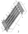
- the picking warehouse for general cargo and especially for food in cardboard containers, that have a very high turnover rate in the wholesale sector primarily from a storage area 1, a storage area 1 upstream Assembly area 2 and a picking area downstream of the storage area 1 3 together.
- the storage takes place in the assembly area 2 new goods to be stored in the correct storage location within the storage area 1.
- the individual piece goods are accordingly removed from storage area 1 by computer from the Commission and to a place where the compilation and if necessary The commissions are packaged into larger packaging containers.
- Removal of the individual goods from storage area 1 are removal devices 4 provided that the goods removed from the storage area 1 individually place on a transport path 5, along which the further transport of the Goods done.
- the goods in the assembly area 2 are also conveyed by means of a continuously driven conveyor track 6, which, like the conveyor track 5 in the picking area 3, from a variety of driven Transport rollers 6a composed on which the transported piece goods roll along.
- the storage area 1 is composed of a plurality arranged at a uniform height and parallel aligned lanes 7 together.
- the Warehouse aisles 7 are slightly inclined and descending towards the picking area 3 arranged and consist of roller tracks 8 from freely rotatable rollers or Rollers.
- the individual warehouse aisles 7 are separated by limits 9 so that goods are not accidentally can get into neighboring storage aisles. Every camp aisle is with Provide braking devices with which the rollers or rollers individually or brake in groups so that they roll along the storage aisles Were not reaching too high a speed.
- the rollers can be provided with wheel flanges.
- each warehouse aisle there are 7 in each warehouse aisle only goods or piece goods of the same type. 1 and 2 shown, consisting of a total of four storage aisles 1 therefore four different types of goods can be stored.
- the goods the same type of goods are arranged one behind the other in the respective warehouse aisle 7, whereby they automatically move up to due to the inclination of the roller conveyor 8 move the end of the warehouse aisle 7 facing the picking area 3, and the foremost product is held there at a limit stop 23.
- a total of four storage aisles 7 form together a module 10.
- modules can be arranged side by side be, so that, depending on the spatial conditions, up to one hundred storage aisles side by side and with common facilities of the Arrange assembly area 2 and picking area 3.
- the order picking warehouse shown can also be stacked several times be arranged so as to multiply the space utilization.
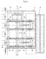
- the transport track 6 is common to all storage lanes 7, which is why via the transport track 6 goods of very different types can also be transported.
- Around Classifying goods in the correct warehouse aisle 7 is the one in FIG. 1 illustrated embodiment above the conveyor track 6, a cross conveyor 11 arranged with the conveying direction 12 in the direction of the storage lanes 7.
- the cross conveyor 11 is adjustable along the transport path 6 according to the arrow 11a, and so on to take a position in front of the storage alley 7 to be populated.
- the cross conveyor 11 is arranged with respect to the transport path 6 that about the goods 6 arriving in the third storage lane from the right.
- the cross conveyor 11 is preferably a belt conveyor with a high coefficient of friction, so that goods also cross to the direction of transport the transport path 6 can be moved on the transport rollers 6a.
- the setting of the cross conveyor 11 with respect to the length of the transport path 6 is carried out fully automatically depending on the transport path 6 supplied product group. Their identification can e.g. B. using a barcode take place, which is on the piece goods.
- each storage aisle 7 can be one own, reaching between the transport rollers 6a of the transport path 6 Cross conveyor 13 may be assigned. This can be constructed similarly to the removal device 4th
- the A side of the transport path 6 facing away from storage lanes 7 is a second picking area be arranged so that the transport path 6 on both sides Have the picking areas loaded.
- this Case can also transport the cross conveyor 11, 13 in both directions.
- the goods are picked in the picking area 3 by means of the removal devices 4 taken individually from the storage aisles and onto the common one Conveyed transport path 5, which extends across the storage lanes 7.
- Pollerförrnige Rollers 14 with a horizontal axis of rotation cause a tilt-free Transfer and redirect the goods from the removal device 4 to the Transport lane 5.
- Each individual storage lane 7 is a separate removal device 4 assigned, which is why goods removed from several storage aisles 7 at the same time and can be transferred to the transport track 5.
- Each removal device 4 is composed of a horizontal conveyor 15 and one Lifting mechanism together.
- the horizontal conveyor 15 is located in Extension and alignment to the Lagergasse 7.
- the horizontal conveyor 15 exists from several endless belts guided over pulleys and is enough its rear end 16 viewed in the conveying direction into the respective warehouse aisle 7 in. To enable this overlap of the two transport systems, there can be 8 free spaces between the rollers of the roller conveyor, into which the transport belts of the horizontal conveyor 15 fit.
- the front end 17 of the horizontal conveyor 15 viewed in the conveying direction extends close to the transport track 5, so that a delay-free at this location and gentle transfer of the goods to the transport track 5 achieved is additionally supported by the bollard-shaped rollers shown in FIG. 1 14th
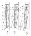
- the in the Figs. 3a to 3d lifting mechanism not shown in detail Removal device 4 serves the horizontal conveyor 15, but at least its effective conveying area to raise.
- the horizontal conveyor 15 pivotable about an axis 18 disposed near its front end 17, whereby the rear end 16 of the horizontal conveyor 15 can be raised.
- Actuation of the lifting mechanism therefore reaches the effective conveying surface of the Horizontal conveyor 15 from the passive position 19 shown in Fig. 3a in the in contrast, raised, active position 19 '. Only in the active position 19 ' engages the conveying surface of the horizontal conveyor 15 from below under that in the storage aisle 7 foremost goods 20 so that they are gripped by the horizontal conveyor 15 and shown in different steps in FIGS. 2b to 2d Way is transferred to the transport path 5.
- the horizontal conveyor 15 is only then driven when it is shown in dashed lines in FIGS. 3a to 3d, active position 19 '. However, the horizontal conveyor 15 is located in the passive position 19, it stands still.
- FIGS. 4a to 4c, 5 and 6 described second embodiment.
- the horizontal conveyor works here 15 in continuous operation, d. H. he runs even when he is at non-actuated lifting mechanism in its lowered, passive position 19 located.
- the horizontal conveyor 15 runs "empty" in this case, and takes the foremost Goods 20 only due to its lifting and contacting the underside the goods 20.
- the advantage of this design option is that the drive of several horizontal conveyors 15 via a common drive shaft can be done.
- This common drive shaft is also the axis 18 around which around the individual horizontal conveyors 15 from the passive position 19 to the active one Position 19 'are pivotable.
- control is therefore carried out of the individual removal devices 4 exclusively by pressing the Lifting mechanism while the actual conveying movement runs continuously. Every time, by controlling the lifting mechanism of the horizontal conveyor 15 moves from its passive to the active position, a single item 20 taken from the respective storage lane 7.
- the second foremost Goods 21 is gripped by the horizontal conveyor 15 is in the range of rear, liftable end 16 of the horizontal conveyor 15 attached a stop 22, against which the second foremost product 21 comes.
- This product 21 can therefore Do not continue to roll on the roller conveyor 8 as long as the horizontal conveyor 15 is in its active position 19 '.
- the stop 22 gives the following Goods 21 free, so that this up to the front limit stop 23rd the Lagergasse 7 can roll forward and is the new front item.
- the limit stop 23 protrudes over the contact surface of the storage lane 7 addition, which is why the horizontal conveyor 15 so far by means of the lifting mechanism can be raised that the conveying surface of the horizontal conveyor 15 above this Limit stop 23 is located.
- FIGS. 3a to 3d the structure of the removal devices show more schematically, are based on the Figs. 4a to 4c, 5 and 6 also explained the construction details of the removal devices:
- the horizontal conveyor 15 of the removal device 4 consists of a first one Pulley 24, the axis of which coincides with the drive shaft 18 and with this is rotatably connected, and a second, more facing the roller conveyor 8 Pulley 25.
- An endless leads over both pulleys 24, 25 Belt 26 with a non-slip surface.
- the pulley 25 is in a housing 27 mounted, which is pivotable about an axis of rotation 28 near the transport path 5 is.
- To partially raise the horizontal conveyor 15 from the in Fig. 4a shown passive position in the active position shown in Fig. 4b and 4c Position is its rear end 16, which reaches the end of the roller conveyor 8 pivotable about the axis of rotation 28.
- the housing 27 pivotable rear pulley 25 from its lower to its higher position, whereby the goods 20 lying against the limit stop 23 by then is gripped from below and transported in the direction of the transport path 5.
- This transport is shown in FIGS. 4b and 4c.
- the stop 22 projects according to Fig. 4c on the conveyor level of the roller conveyor, so that the following Goods 21 initially only reached the stop 22. Now after Lowering the removal device again into the passive one shown in FIG. 4a This item can also be positioned up to the rigid limit stop 23 then roll.
- each the removal devices 4 has its own magnetic coupling 29 which can also be controlled separately from the other magnetic clutches.
- the magnetic clutch 29 surrounds the drive shaft 18 in a ring and is supported by a Articulated lever 30 from below against the housing 27 of the horizontal conveyor 15 In this way, the drive torque of the drive shaft 18 can be via the magnetic coupling 29 convert into a pivoting movement of the articulated lever 30, so that the housing 27 is pivoted about its axis of rotation 28 upwards.
- the Force to lift the horizontal conveyor, including those supported on it Goods 20 is therefore exclusively from the existing rotational movement of the Drive shaft 18 derived.
- the one required for each individual control process additional energy is therefore limited to the relatively low energy of the electric magnetic coupling 29.
- Transmission linkage 31 can be used, which is parallel to the drive shaft 18 extends. In this way it is possible to simultaneously use several articulated levers 30 insert, whereby the housing 27 lift tilt-free leaves. This is particularly advantageous because in the exemplary embodiment each horizontal conveyor 15 to achieve a wide contact area over total has four straps 26.
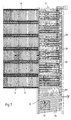
- Fig. 5 shows that the longitudinal axes of the transport rollers 6a of the transport path 5 at an angle ⁇ obliquely to the transport direction of the roller conveyors 8 are arranged. This results in the transportation of the goods along the transport path 5 not only a conveying component in the direction of the transport path itself, but a second funding component away from the storage aisles.
- a commodity or a piece good 32 is shown sequentially in FIG. 5, like this very quickly due to the arrangement of the transport rollers 6a
- the outer edge 33 of the transport path 5 arrives. In this way it is avoided that removed and transported along the transport path 5 piece goods from the subsequent general aisles hinder the emergence of general cargo.
- FIG. 7 arrive incoming piece goods 32 by tilting the transport rollers 6b at the angle ⁇ to that edge 33 of the transport path 6 that is immediately past the warehouse lanes. This ensures that incoming General cargo 32 are always on this edge of the transport path before the piece goods reach the individual warehouse aisles.
- the transport rollers 6a are aligned straight, d. H. aligned with the warehouse aisles.
- the cross conveyor 13 are located between successive transport rollers 6a.
- the driven transport rollers 6a point in the transport direction a sufficient distance from each other.
- the cross conveyor 13 works as well as above for the picking area of the picking warehouse was explained using endless belts 34 that over pulleys 35, 36 are guided.
- the pulleys 35 are driven, via a for all cross conveyor 13 common drive shaft 37.
- the cross conveyor 13 are located in a housing pivotable about an axis of rotation 38 39.
- the axis of rotation 38 is located at the end facing away from the storage aisles of the cross conveyor.
- FIG. 8a this is in its passive position.
- the piece goods 32 roll along of the transport rollers 6a without cross-conveying.
- FIG. 8b With actuation of the cross conveyor raises it according to FIG. 8b, the housing 39 being around the axis of rotation 38 pivots.
- the geometric relationships are such that the effective conveying surface of belt 34 and transport rollers 6a then on same height when the effective conveying surface of the belt 34 and extend the top of the transport rollers 6a exactly parallel to each other. This Case is shown in Fig. 8b. Then, as shown in FIG.
- Such an obstacle may be the flange 41 of the transport rollers 6a.
- the lifting mechanism for pivoting the housing 39 about the axis of rotation 38 works the same as above with reference to FIGS. 3a to 3d and 4a to 4c for the removal devices explained: the drive of all Cross conveyor 13 takes place via the common drive shaft 37, furthermore each has Cross conveyor 13 via its own magnetic coupling 29 for deriving the movement the drive shaft 37 on the pivoting and thus partially lifting of the housing 39 of the cross conveyor.
- each magnetic coupling is 29 Can be controlled separately from the other magnetic clutches, so as to be internal to the system to be able to select that warehouse lane 7 into which those rolling over the transport track 6 General cargo should be sorted.
Landscapes
- Engineering & Computer Science (AREA)
- Mechanical Engineering (AREA)
- Warehouses Or Storage Devices (AREA)
Claims (18)
- Magasin de préparation de commandes constitué :caractérisé en ce que,d'une zone d'entreposage (1) comportant une pluralité de pistes d'entreposage (7) qui s'y étendent parallèlement entre elles, qui sont composées de transporteurs à galets (8) et qui sont chacune destinées à des marchandises d'un même type,d'une zone d'alimentation (2) située à l'une des extrémités des pistes d'entreposage (7) et comportant des moyens d'emmagasinage de nouvelles marchandises dans les pistes d'entreposage associées (7) etd'une zone de préparation de commandes (3) située à l'autre extrémité des pistes d'entreposage (7) et comportant, pour chacune des pistes d'entreposage (7), des dispositifs d'enlèvement séparés (4) servant au transfert commandé par ordinateur de marchandises individuelles des pistes d'entreposage (7) aux dispositifs de transport disposés en aval, chaque dispositif d'enlèvement (4) étant équipé d'un convoyeur horizontal (15) destiné aux marchandises (20) à évacuer,
outre le convoyeur horizontal (15), un butoir mobile (22) tourné vers la piste d'entreposage (7) et servant à retenir les marchandises suivantes (21) est une partie constitutive de chacun des dispositifs d'enlèvement (4),
en ce que le convoyeur horizontal (15) est entraíné, et en ce que non seulement le mouvement d'entraínement du convoyeur horizontal (15) mais aussi le mouvement du butoir (22) sont dérivés du mouvement rotatif d'un arbre de transmission commun (18). - Magasin de préparation de commandes selon la revendication 1, caractérisé en ce qu'une voie de transport (5) continuellement entraínée et destinée aux marchandises enlevées s'étend le long des dispositifs d'enlèvement (4) et transversalement aux pistes d'entreposage (7).
- Magasin de préparation de commandes selon la revendication 1, caractérisé en ce que les galets ou les cylindres des transporteurs à galets (8) peuvent être freinés individuellement ou par groupes.
- Magasin de préparation de commandes selon l'une des revendications précédentes, caractérisé par un mécanisme de levage propre à chacun des dispositifs d'enlèvement (4) et servant à lever, au moins partiellement, le convoyeur horizontal (15).
- Magasin de préparation de commandes selon la revendication 4, caractérisé en ce que le convoyeur horizontal (15) peut être soulevé par le mécanisme de levage jusqu'à une hauteur à laquelle la surface de transport efficace du convoyeur horizontal (15) se trouve au-dessus de la surface de contact des colis de détail placés sur le transporteur à galets (8).
- Magasin de préparation de commandes selon l'une des revendications 1 à 5, caractérisé en ce que l'entraínement d'une pluralité des dispositifs d'enlèvement (4) a lieu au moyen d'un arbre de transmission commun (18) qui s'étend transversalement aux pistes d'entreposage (7).
- Magasin de préparation de commandes selon l'une des revendications 4 à 6, caractérisé en ce que chacune des pistes d'entreposage (7) est munie, à son extrémité tournée vers la zone de préparation de commandes (3), d'une butée de limitation (23) faisant saillie au-dessus de la surface de contact des marchandises et contre laquelle la marchandise de tête (20) du moment prend appui, et en ce que le convoyeur horizontal (15) du dispositif d'enlèvement (4) peut être soulevé au moyen du mécanisme de levage jusqu'à une hauteur à laquelle la surface de transport efficace du convoyeur horizontal (15) se trouve au-dessus de la butée de limitation (23).
- Magasin de préparation de commandes selon la revendication 7, caractérisé en ce que le butoir (22) est configuré de manière à pouvoir être soulevé conjointement avec le convoyeur horizontal (15).
- Magasin de préparation de commandes selon l'une des revendications 4 à 8, caractérisé en ce que, pour soulever partiellement le convoyeur horizontal (15), son extrémité arrière (16) qui va jusque dans la piste d'entreposage (7) peut basculer autour d'un axe de rotation (28).
- Magasin de préparation de commandes selon l'une des revendications 4 à 9, caractérisé par un accouplement à aimant (29) servant, lors du soulèvement au moins partiel du convoyeur horizontal (15), à tirer le mouvement du mouvement rotatif de l'arbre de transmission commun (18), l'accouplement à aimant (29) de chacun des dispositifs d'enlèvement (4) pouvant être commandé indépendamment de tous les autres accouplements à aimant (29).
- Magasin de préparation de commandes selon la revendication 10, caractérisé en ce que l'accouplement à aimant (29) entoure l'arbre de transmission (18) en formant un anneau et en ce qu'il prend appui par le dessous, par l'intermédiaire d'un levier articulé (30), contre le boítier (27) du convoyeur horizontal (15).
- Magasin de préparation de commandes selon l'une des revendications 1 à 11, caractérisé en ce que le convoyeur horizontal (15) se compose d'une première poulie (24) reliée solidairement à l'arbre de transmission (18), d'au moins une autre poulie rotative (25) ainsi que d'une courroie sans fin (26) passant sur les poulies (24, 25), la poulie entraínée (24) déterminant l'extrémité avant (17) et la poulie rotative (25) déterminant l'extrémité arrière (16) du convoyeur horizontal (15).
- Magasin de préparation de commandes selon l'une des revendications précédentes, caractérisé par un dispositif de transport (6) entraíné de façon continue qui s'étend transversalement aux pistes d'entreposage (7) dans la zone d'alimentation (2) et qui est composé de cylindres de transport individuels (6a), lequel est destiné aux marchandises à nouvellement entreposer.
- Magasin de préparation de commandes selon la revendication 13, caractérisé par des convoyeurs transversaux (13) qui sont disposés entre les cylindres de transport (6a), qui peuvent être actionnés séparément pour chacune des pistes d'entreposage (7) et dont le sens de transport (12) est orienté vers leur piste d'entreposage respective (7).
- Magasin de préparation de commandes selon la revendication 14, caractérisé en ce que chaque convoyeur transversal (13) est pourvu d'un mécanisme de levage propre servant au levage au moins partiel du convoyeur transversal, la surface de transport efficace (40) du convoyeur transversal étant placée au-dessous de la face supérieure des cylindres de transport lorsque le mécanisme de levage n'est pas actionné et au moins partiellement au-dessus de la face supérieure des cylindres de transport (6a) lorsque le mécanisme de levage est actionné.
- Magasin de préparation de commandes selon la revendication 15, caractérisé en ce que le convoyeur transversal (13) se compose de plusieurs poulies (35, 36) sur lesquelles passe une courroie sans fin (34) dont la face supérieure constitue la surface de transport efficace (40) du convoyeur transversal (13).
- Magasin de préparation de commandes selon la revendication 15 ou la revendication 16, caractérisé en ce que l'entraínement d'une pluralité de convoyeurs transversaux (13) a lieu au moyen d'un arbre de transmission commun (37) et en ce que chacun des convoyeurs transversaux (13) dispose de son propre accouplement à aimant (29) servant, lors du levage au moins partiel du convoyeur transversal, à prélever le mouvement sur le mouvement rotatif de l'arbre de transmission commun (37), l'accouplement à aimant (29) de chaque convoyeur transversal (13) pouvant être commandé séparément du reste des autres accouplements à aimant (29).
- Magasin de préparation de commandes selon la revendication 2, caractérisé en ce que la voie de transport (5) se compose de cylindres de transport ayant une largeur efficace d'au moins le double de la largeur des galets ou des cylindres du transporteur à galets (8) et en ce que l'axe longitudinal des cylindres de transport est disposé de manière à former un angle (α) avec la direction des pistes d'entreposage (7) et de façon à créer une composante de transport s'éloignant des pistes d'entreposage (7).
Applications Claiming Priority (2)
| Application Number | Priority Date | Filing Date | Title |
|---|---|---|---|
| DE19823083A DE19823083A1 (de) | 1998-05-22 | 1998-05-22 | Kommissionierlager für Stückgüter |
| DE19823083 | 1998-05-22 |
Publications (3)
| Publication Number | Publication Date |
|---|---|
| EP0965543A2 EP0965543A2 (fr) | 1999-12-22 |
| EP0965543A3 EP0965543A3 (fr) | 2001-09-26 |
| EP0965543B1 true EP0965543B1 (fr) | 2003-08-06 |
Family
ID=7868708
Family Applications (1)
| Application Number | Title | Priority Date | Filing Date |
|---|---|---|---|
| EP99107698A Expired - Lifetime EP0965543B1 (fr) | 1998-05-22 | 1999-04-17 | Magasin de commission pour marchandises |
Country Status (6)
| Country | Link |
|---|---|
| US (1) | US6186724B1 (fr) |
| EP (1) | EP0965543B1 (fr) |
| AT (1) | ATE246652T1 (fr) |
| DE (2) | DE19823083A1 (fr) |
| DK (1) | DK0965543T3 (fr) |
| ES (1) | ES2204024T3 (fr) |
Families Citing this family (28)
| Publication number | Priority date | Publication date | Assignee | Title |
|---|---|---|---|---|
| DE19905967B4 (de) * | 1999-02-12 | 2004-02-05 | Dynamic Systems Engineering B.V. | Anlage zur Warenkommissionierung, insbesondere zur Kommissionierung von Lebensmitteln in rechteckigen Paketgebinden |
| DE10020608A1 (de) * | 2000-04-27 | 2001-10-31 | Dynamic Systems Engineering B | Lager- und/oder Transportvorrichtung für Stückgüter |
| ES2166330B1 (es) * | 2000-05-17 | 2003-02-16 | Gomez Gines Sanchez | Almacen automatico optimizado. |
| US6615104B2 (en) | 2001-05-01 | 2003-09-02 | Nintendo Of America, Inc. | System and method of selecting box size |
| NO20020585L (no) * | 2002-02-05 | 2003-08-06 | Zopa As | System og fremgangsmate for a overfore produkter fra et oppbevaringsomrade til et utleveringsomrade |
| US7184855B2 (en) * | 2002-03-13 | 2007-02-27 | Stingel Iii Frederick J | Automated container storage and delivery system |
| US6729836B2 (en) * | 2002-03-13 | 2004-05-04 | Stingel, Iii Frederick J. | Automated container storage and delivery system |
| US6871116B2 (en) * | 2002-10-17 | 2005-03-22 | Vertique, Inc. | Determining pallet case configurations for placement by a robot |
| DE102004046439A1 (de) * | 2004-09-24 | 2006-04-06 | Siemens Ag | Vorrichtung zum Ein- und Ausschleusen von Ladungsträgern oder Stückgütern |
| CA2524414C (fr) * | 2004-10-26 | 2014-01-14 | 3584925 Canada Inc. | Systeme d'assortiment de commandes automatise |
| AT501825B1 (de) * | 2005-05-11 | 2007-03-15 | Sticht Fertigungstech Stiwa | Fördersystem zum fördern und vereinzeln von teilen |
| NL1030328C2 (nl) * | 2005-11-01 | 2007-05-03 | Trm Patenten B V | Systeem voor het rangschikken en/of opslaan van objecten. |
| DE102006048345A1 (de) * | 2006-10-12 | 2008-04-17 | Köra-Packmat Maschinenbau GmbH | Transportverfahren |
| US7963384B2 (en) * | 2008-12-19 | 2011-06-21 | 3584925 Canada Inc. | Automated order sequencing method and system |
| US8540038B1 (en) | 2009-01-09 | 2013-09-24 | The United States Of America As Represented By The Secretary Of The Navy | Low profile omnidirectional vehicle |
| DE102011106667A1 (de) | 2011-07-05 | 2013-01-10 | SSI Schäfer Noell GmbH Lager- und Systemtechnik | Lager- und Kommissioniersystem und Verfahren zum automatisierten Kommissionieren mit einem Kanallager |
| US20130062160A1 (en) * | 2011-09-14 | 2013-03-14 | Jeffrey J. Steinbach | Article tray and handling of articles with the tray |
| DE102012101267A1 (de) * | 2012-02-17 | 2013-08-22 | Wincor Nixdorf International Gmbh | Kassensystemanordnung |
| CN104289449B (zh) * | 2013-07-19 | 2019-10-18 | 李斌云 | 万向分拣平台 |
| ITVI20130214A1 (it) * | 2013-08-09 | 2015-02-10 | Idea Srl | Magazzino automatico |
| DE102015213195A1 (de) * | 2015-07-14 | 2017-01-19 | Siemens Aktiengesellschaft | Transportrutsche mit Antriebsmittel |
| FI130923B1 (en) * | 2018-05-04 | 2024-05-29 | Actiw Oy | Grouping station for grouping pallets |
| FR3096364B1 (fr) * | 2019-05-23 | 2021-10-29 | Savoye | Procédé de traitement d’une liste de commandes dans un système de préparation de commandes, et poste de préparation correspondant. |
| CN112634541A (zh) * | 2020-12-18 | 2021-04-09 | 广州卓腾科技有限公司 | 用于车管自助设备的发皮套装置 |
| CN113145478B (zh) * | 2021-04-28 | 2025-04-04 | 浙江百世技术有限公司 | 一种物流分拣装置 |
| DE102021124545B4 (de) | 2021-09-22 | 2025-08-07 | Stöcklin Logistik Ag | Vorrichtung und Verfahren zur Sequenzierung von Ladeeinheiten in einer vorbestimmten Reihenfolge |
| TWI895527B (zh) * | 2021-10-19 | 2025-09-01 | 日商大福股份有限公司 | 物品搬送裝置 |
| EP4190725A1 (fr) * | 2021-12-02 | 2023-06-07 | Primetals Technologies Austria GmbH | Dispositif de transport et procédé de transport des faisceaux de bandes métalliques |
Family Cites Families (12)
| Publication number | Priority date | Publication date | Assignee | Title |
|---|---|---|---|---|
| US3108677A (en) * | 1960-11-25 | 1963-10-29 | Baker Perkins Inc | Pan transfer apparatus |
| CH432366A (de) * | 1963-04-02 | 1967-03-15 | Electrolux Ab | Speicheranordnung |
| DE1243106B (de) * | 1964-01-27 | 1967-06-22 | Guenther Zagelow Dipl Ing | Speicher- und Ausgabeeinrichtung fuer Foerderguttraeger |
| SE363794B (fr) * | 1971-04-26 | 1974-02-04 | Electrolux Ab | |
| DE2121622A1 (de) * | 1971-05-03 | 1972-11-16 | Meyer, Heinz-Jürgen, Dipl.-Ing., 6149Rimbach | Regal zur Aufnahme von Lagergegen; ständen |
| JPS5772505A (en) * | 1980-10-21 | 1982-05-06 | Sanki Eng Co Ltd | Rack loader in gravity loading rack device |
| US4383598A (en) * | 1981-12-28 | 1983-05-17 | Newman Frank E | Conveyor control apparatus |
| JPS58212501A (ja) * | 1982-05-31 | 1983-12-10 | Kao Corp | ピッキング装置 |
| US4527937A (en) * | 1983-05-13 | 1985-07-09 | Orion Automation Industries | Automatic storage and distribution system |
| NL8502715A (nl) * | 1985-10-04 | 1987-05-04 | Elten Nederland | Installatie voor het verzamelen van kratten. |
| DE3920405C1 (fr) * | 1989-06-22 | 1990-03-29 | Goldschmidt, Sol, Zuerich, Ch | |
| AT406151B (de) * | 1995-04-12 | 2000-03-27 | Peem Foerderanlagen Gmbh | Einrichtung zum verteilen von stückgut |
-
1998
- 1998-05-22 DE DE19823083A patent/DE19823083A1/de not_active Withdrawn
-
1999
- 1999-04-17 EP EP99107698A patent/EP0965543B1/fr not_active Expired - Lifetime
- 1999-04-17 DK DK99107698T patent/DK0965543T3/da active
- 1999-04-17 ES ES99107698T patent/ES2204024T3/es not_active Expired - Lifetime
- 1999-04-17 DE DE59906481T patent/DE59906481D1/de not_active Expired - Lifetime
- 1999-04-17 AT AT99107698T patent/ATE246652T1/de active
- 1999-05-21 US US09/316,891 patent/US6186724B1/en not_active Expired - Lifetime
Also Published As
| Publication number | Publication date |
|---|---|
| US6186724B1 (en) | 2001-02-13 |
| EP0965543A2 (fr) | 1999-12-22 |
| DK0965543T3 (da) | 2003-12-01 |
| ES2204024T3 (es) | 2004-04-16 |
| EP0965543A3 (fr) | 2001-09-26 |
| DE59906481D1 (de) | 2003-09-11 |
| ATE246652T1 (de) | 2003-08-15 |
| DE19823083A1 (de) | 1999-11-25 |
Similar Documents
| Publication | Publication Date | Title |
|---|---|---|
| EP0965543B1 (fr) | Magasin de commission pour marchandises | |
| EP1189825B1 (fr) | Dispositif de transport et/ou de stockage pour marchandises en colis | |
| DE3920405C1 (fr) | ||
| AT503572B1 (de) | Fördereinrichtung zum depalettieren von auf einem warenträger gestapelter waren | |
| DE102013104423B4 (de) | Fördersystem und Verfahren zum Be- und Entladen von Stückgütern | |
| DE102011053009A1 (de) | Transfereinrichtung | |
| WO2007134832A2 (fr) | Station de remplissage séparée | |
| EP0095634B1 (fr) | Dispositif pour palettiser des marchandises | |
| EP0396960A2 (fr) | Méthode et installation pour réarranger des objets palettisés par sortes en groupes dont la composition des sortes est définie | |
| DE4303413A1 (de) | Beschickungsvorrichtung für eine Palettiervorrichtung | |
| DE4217079A1 (de) | Einrichtung zur selektiven palettisierung von gegenstaenden mit unterschiedlichen eigenschaften | |
| DE212010000076U1 (de) | Kommissioniereinrichtung | |
| DE102006039697A1 (de) | Vorrichtung und Verfahren zum Entladen von mit Palettenlagen beladenen Tablaren | |
| EP0581398B1 (fr) | Porte-charges et dispositif pour leur vidange | |
| DE2702724A1 (de) | Einrichtung zum sortieren und ablegen von zuschnitten bei plattenaufteilanlagen | |
| AT406151B (de) | Einrichtung zum verteilen von stückgut | |
| EP1144282B1 (fr) | Dispositif pour rassembler et preparer des marchandises de detail | |
| DE20214241U1 (de) | Lagervorrichtung | |
| DE69607698T2 (de) | Vorrichtung zum Be- und/oder Entladen von einem Behälter mit Stapeln von Packungen, insbesondere Eierkartons | |
| EP0852559A1 (fr) | Dispositif et procede pour agencer des contenants en verre sur une palette | |
| EP0697356B1 (fr) | Dispositif pour empiler ou désempiler des marchandises superposables | |
| DE3343732C2 (fr) | ||
| EP1230137B1 (fr) | Dispositif pour rassembler et preparer des marchandises de detail | |
| DE4100234A1 (de) | Anlage zum einlagern von guetern | |
| DE1556734C3 (de) | Einrichtung zum Be- und Entladen von Etagengestellen, insbesondere von Mehretagen-Käse norden |
Legal Events
| Date | Code | Title | Description |
|---|---|---|---|
| PUAI | Public reference made under article 153(3) epc to a published international application that has entered the european phase |
Free format text: ORIGINAL CODE: 0009012 |
|
| AK | Designated contracting states |
Kind code of ref document: A2 Designated state(s): AT BE CH CY DE DK ES FI FR GB GR IE IT LI LU MC NL PT SE Kind code of ref document: A2 Designated state(s): AT BE CH DE DK ES FR GB IT LI NL SE |
|
| AX | Request for extension of the european patent |
Free format text: AL;LT;LV;MK;RO;SI |
|
| PUAL | Search report despatched |
Free format text: ORIGINAL CODE: 0009013 |
|
| AK | Designated contracting states |
Kind code of ref document: A3 Designated state(s): AT BE CH CY DE DK ES FI FR GB GR IE IT LI LU MC NL PT SE |
|
| AX | Request for extension of the european patent |
Free format text: AL;LT;LV;MK;RO;SI |
|
| RIC1 | Information provided on ipc code assigned before grant |
Free format text: 7B 65G 1/06 A, 7B 65G 1/08 B, 7B 65G 47/88 B, 7B 65G 1/137 B, 7B 65G 47/54 B |
|
| 17P | Request for examination filed |
Effective date: 20011029 |
|
| GRAG | Despatch of communication of intention to grant |
Free format text: ORIGINAL CODE: EPIDOS AGRA |
|
| GRAG | Despatch of communication of intention to grant |
Free format text: ORIGINAL CODE: EPIDOS AGRA |
|
| GRAH | Despatch of communication of intention to grant a patent |
Free format text: ORIGINAL CODE: EPIDOS IGRA |
|
| 17Q | First examination report despatched |
Effective date: 20020218 |
|
| GRAH | Despatch of communication of intention to grant a patent |
Free format text: ORIGINAL CODE: EPIDOS IGRA |
|
| AKX | Designation fees paid |
Free format text: AT BE CH DE DK ES FR GB IT LI NL SE |
|
| GRAA | (expected) grant |
Free format text: ORIGINAL CODE: 0009210 |
|
| AK | Designated contracting states |
Designated state(s): AT BE CH DE DK ES FR GB IT LI NL SE |
|
| REG | Reference to a national code |
Ref country code: GB Ref legal event code: FG4D Free format text: NOT ENGLISH |
|
| REG | Reference to a national code |
Ref country code: CH Ref legal event code: EP |
|
| GBT | Gb: translation of ep patent filed (gb section 77(6)(a)/1977) |
Effective date: 20030806 |
|
| REG | Reference to a national code |
Ref country code: CH Ref legal event code: NV Representative=s name: DR. LUSUARDI AG |
|
| REF | Corresponds to: |
Ref document number: 59906481 Country of ref document: DE Date of ref document: 20030911 Kind code of ref document: P |
|
| REG | Reference to a national code |
Ref country code: SE Ref legal event code: TRGR |
|
| REG | Reference to a national code |
Ref country code: DK Ref legal event code: T3 |
|
| ET | Fr: translation filed | ||
| REG | Reference to a national code |
Ref country code: ES Ref legal event code: FG2A Ref document number: 2204024 Country of ref document: ES Kind code of ref document: T3 |
|
| PLBE | No opposition filed within time limit |
Free format text: ORIGINAL CODE: 0009261 |
|
| STAA | Information on the status of an ep patent application or granted ep patent |
Free format text: STATUS: NO OPPOSITION FILED WITHIN TIME LIMIT |
|
| 26N | No opposition filed |
Effective date: 20040507 |
|
| REG | Reference to a national code |
Ref country code: CH Ref legal event code: PFA Owner name: DYNAMIC SYSTEMS ENGINEERING BV Free format text: DYNAMIC SYSTEMS ENGINEERING BV#KOOPMANSLAAN 3#7005 BK DOETINCHEM (NL) -TRANSFER TO- DYNAMIC SYSTEMS ENGINEERING BV#KOOPMANSLAAN 3#7005 BK DOETINCHEM (NL) |
|
| REG | Reference to a national code |
Ref country code: DE Ref legal event code: R082 Ref document number: 59906481 Country of ref document: DE Representative=s name: BUNGARTZ CHRISTOPHERSEN PARTNERSCHAFT MBB PATE, DE |
|
| REG | Reference to a national code |
Ref country code: FR Ref legal event code: PLFP Year of fee payment: 17 |
|
| PGFP | Annual fee paid to national office [announced via postgrant information from national office to epo] |
Ref country code: ES Payment date: 20150427 Year of fee payment: 17 Ref country code: CH Payment date: 20150422 Year of fee payment: 17 Ref country code: SE Payment date: 20150423 Year of fee payment: 17 Ref country code: DK Payment date: 20150424 Year of fee payment: 17 Ref country code: GB Payment date: 20150423 Year of fee payment: 17 |
|
| PGFP | Annual fee paid to national office [announced via postgrant information from national office to epo] |
Ref country code: FR Payment date: 20150422 Year of fee payment: 17 Ref country code: BE Payment date: 20150430 Year of fee payment: 17 |
|
| PG25 | Lapsed in a contracting state [announced via postgrant information from national office to epo] |
Ref country code: BE Free format text: LAPSE BECAUSE OF NON-PAYMENT OF DUE FEES Effective date: 20160430 |
|
| REG | Reference to a national code |
Ref country code: DK Ref legal event code: EBP Effective date: 20160430 |
|
| REG | Reference to a national code |
Ref country code: SE Ref legal event code: EUG |
|
| REG | Reference to a national code |
Ref country code: CH Ref legal event code: PL |
|
| GBPC | Gb: european patent ceased through non-payment of renewal fee |
Effective date: 20160417 |
|
| REG | Reference to a national code |
Ref country code: FR Ref legal event code: ST Effective date: 20161230 |
|
| PG25 | Lapsed in a contracting state [announced via postgrant information from national office to epo] |
Ref country code: CH Free format text: LAPSE BECAUSE OF NON-PAYMENT OF DUE FEES Effective date: 20160430 Ref country code: FR Free format text: LAPSE BECAUSE OF NON-PAYMENT OF DUE FEES Effective date: 20160502 Ref country code: GB Free format text: LAPSE BECAUSE OF NON-PAYMENT OF DUE FEES Effective date: 20160417 Ref country code: LI Free format text: LAPSE BECAUSE OF NON-PAYMENT OF DUE FEES Effective date: 20160430 |
|
| PG25 | Lapsed in a contracting state [announced via postgrant information from national office to epo] |
Ref country code: SE Free format text: LAPSE BECAUSE OF NON-PAYMENT OF DUE FEES Effective date: 20160418 |
|
| PG25 | Lapsed in a contracting state [announced via postgrant information from national office to epo] |
Ref country code: DK Free format text: LAPSE BECAUSE OF NON-PAYMENT OF DUE FEES Effective date: 20160430 |
|
| PG25 | Lapsed in a contracting state [announced via postgrant information from national office to epo] |
Ref country code: ES Free format text: LAPSE BECAUSE OF NON-PAYMENT OF DUE FEES Effective date: 20160418 |
|
| PGFP | Annual fee paid to national office [announced via postgrant information from national office to epo] |
Ref country code: NL Payment date: 20180423 Year of fee payment: 20 |
|
| PGFP | Annual fee paid to national office [announced via postgrant information from national office to epo] |
Ref country code: DE Payment date: 20180515 Year of fee payment: 20 |
|
| PGFP | Annual fee paid to national office [announced via postgrant information from national office to epo] |
Ref country code: IT Payment date: 20180420 Year of fee payment: 20 Ref country code: AT Payment date: 20180418 Year of fee payment: 20 |
|
| REG | Reference to a national code |
Ref country code: ES Ref legal event code: FD2A Effective date: 20181128 |
|
| REG | Reference to a national code |
Ref country code: DE Ref legal event code: R071 Ref document number: 59906481 Country of ref document: DE Ref country code: NL Ref legal event code: MK Effective date: 20190416 |
|
| REG | Reference to a national code |
Ref country code: AT Ref legal event code: MK07 Ref document number: 246652 Country of ref document: AT Kind code of ref document: T Effective date: 20190417 |