EP0965543B1 - Dispensing store for piece goods - Google Patents
Dispensing store for piece goods Download PDFInfo
- Publication number
- EP0965543B1 EP0965543B1 EP99107698A EP99107698A EP0965543B1 EP 0965543 B1 EP0965543 B1 EP 0965543B1 EP 99107698 A EP99107698 A EP 99107698A EP 99107698 A EP99107698 A EP 99107698A EP 0965543 B1 EP0965543 B1 EP 0965543B1
- Authority
- EP
- European Patent Office
- Prior art keywords
- order
- conveyor
- storage
- picking
- horizontal conveyor
- Prior art date
- Legal status (The legal status is an assumption and is not a legal conclusion. Google has not performed a legal analysis and makes no representation as to the accuracy of the status listed.)
- Expired - Lifetime
Links
Images


Classifications
-
- B—PERFORMING OPERATIONS; TRANSPORTING
- B65—CONVEYING; PACKING; STORING; HANDLING THIN OR FILAMENTARY MATERIAL
- B65G—TRANSPORT OR STORAGE DEVICES, e.g. CONVEYORS FOR LOADING OR TIPPING, SHOP CONVEYOR SYSTEMS OR PNEUMATIC TUBE CONVEYORS
- B65G1/00—Storing articles, individually or in orderly arrangement, in warehouses or magazines
- B65G1/02—Storage devices
- B65G1/04—Storage devices mechanical
- B65G1/06—Storage devices mechanical with means for presenting articles for removal at predetermined position or level
- B65G1/08—Storage devices mechanical with means for presenting articles for removal at predetermined position or level the articles being fed by gravity
-
- B—PERFORMING OPERATIONS; TRANSPORTING
- B65—CONVEYING; PACKING; STORING; HANDLING THIN OR FILAMENTARY MATERIAL
- B65G—TRANSPORT OR STORAGE DEVICES, e.g. CONVEYORS FOR LOADING OR TIPPING, SHOP CONVEYOR SYSTEMS OR PNEUMATIC TUBE CONVEYORS
- B65G1/00—Storing articles, individually or in orderly arrangement, in warehouses or magazines
- B65G1/02—Storage devices
- B65G1/04—Storage devices mechanical
- B65G1/137—Storage devices mechanical with arrangements or automatic control means for selecting which articles are to be removed
- B65G1/1373—Storage devices mechanical with arrangements or automatic control means for selecting which articles are to be removed for fulfilling orders in warehouses
- B65G1/1378—Storage devices mechanical with arrangements or automatic control means for selecting which articles are to be removed for fulfilling orders in warehouses the orders being assembled on fixed commissioning areas remote from the storage areas
-
- B—PERFORMING OPERATIONS; TRANSPORTING
- B65—CONVEYING; PACKING; STORING; HANDLING THIN OR FILAMENTARY MATERIAL
- B65G—TRANSPORT OR STORAGE DEVICES, e.g. CONVEYORS FOR LOADING OR TIPPING, SHOP CONVEYOR SYSTEMS OR PNEUMATIC TUBE CONVEYORS
- B65G47/00—Article or material-handling devices associated with conveyors; Methods employing such devices
- B65G47/74—Feeding, transfer, or discharging devices of particular kinds or types
- B65G47/88—Separating or stopping elements, e.g. fingers
- B65G47/8807—Separating or stopping elements, e.g. fingers with one stop
- B65G47/8823—Pivoting stop, swinging in or out of the path of the article
-
- B—PERFORMING OPERATIONS; TRANSPORTING
- B65—CONVEYING; PACKING; STORING; HANDLING THIN OR FILAMENTARY MATERIAL
- B65G—TRANSPORT OR STORAGE DEVICES, e.g. CONVEYORS FOR LOADING OR TIPPING, SHOP CONVEYOR SYSTEMS OR PNEUMATIC TUBE CONVEYORS
- B65G47/00—Article or material-handling devices associated with conveyors; Methods employing such devices
- B65G47/74—Feeding, transfer, or discharging devices of particular kinds or types
- B65G47/88—Separating or stopping elements, e.g. fingers
- B65G47/8807—Separating or stopping elements, e.g. fingers with one stop
- B65G47/883—Fixed stop
- B65G47/8853—Fixed stop with conveyors, e.g. pivoting or rotating, to transfer the article
-
- B—PERFORMING OPERATIONS; TRANSPORTING
- B65—CONVEYING; PACKING; STORING; HANDLING THIN OR FILAMENTARY MATERIAL
- B65G—TRANSPORT OR STORAGE DEVICES, e.g. CONVEYORS FOR LOADING OR TIPPING, SHOP CONVEYOR SYSTEMS OR PNEUMATIC TUBE CONVEYORS
- B65G2205/00—Stopping elements used in conveyors to stop articles or arrays of articles
- B65G2205/04—Stopping elements used in conveyors to stop articles or arrays of articles where the stop device is not adaptable
Definitions
- the invention relates to a picking warehouse for piece goods according to the preamble of claim 1.
- the warehouse technology is penalizing in the narrower sense, d. H. the static storage of the individual piece goods, rather important, whereas the dynamic processes and primarily the handling of goods becomes more important.
- the aim of modern warehouse technology It is therefore the length of time that the individual piece goods remain in the warehouse and thus the capital formation associated with the storage increases as little as possible hold.
- the well-known order-picking warehouse is a multi-storey rack construction side-by-side and stacked aisles for general cargo educated.
- the floors of the storage aisles thus formed are made of roller conveyors Freely rotatable castors and slightly inclined, so that at one end the storage aisles, the so-called loading or loading side Were under their own gravity along the roller conveyors to the other end of the warehouse aisle, the picking or picking side.
- the goods are usually stored on the loading side by Hand picked by hand from a pallet of individual piece goods and used in the assigned warehouse aisle. Picking too often takes place on the removal side of the picking rack by hand; can also be done via controlled removal devices, see e.g. CH 432366A.
- the invention has for its object to provide a picking warehouse with which high turnover rates can be achieved.
- each storage aisle is provided with its own removal device which can be operated independently of the other removal devices; see the characteristics of claim 1.
- the picking warehouse according to the invention enables this way a turnover speed at which, when fully utilized, it ultimately it would even be possible to remove goods from all warehouse aisles at the same time and put together for a commission order.
- removed goods For the removal of the removal devices from the respective storage aisles removed goods is according to a preferred embodiment of the picking warehouse suggested that along the picking devices and a continuously driven one across the storage aisles Transport path for the removed goods extends.
- the individual storage aisles can be inclined in a manner known per se roller conveyors descending towards the picking area from unused, free rotatable rollers or rollers.
- the rollers or rollers can be braked individually or in groups.
- each removal device settles from a horizontal conveyor and its own lifting mechanism at least partial lifting of the horizontal conveyor together.
- the lifting mechanism brings the horizontal conveyor into contact with the respective piece goods, whereupon this is then taken up by the horizontal conveyor and is moved in the direction of the downstream transport device.
- the number of drive elements and the moving individual parts can be reduced, by driving a plurality according to a preferred development the horizontal conveyor takes place via a common drive shaft, which is transverse extends to the warehouse aisles.
- the order picking warehouse is designed with one Existing conveyor alley proposed that the horizontal conveyor, can be raised to a height by means of the lifting mechanism the effective conveying area of the horizontal conveyor above the contact area the goods are on the roller conveyor. In this way it is avoided that the goods in the foremost position in an undefined position in the area between the storage aisle and the removal device, d. H. the horizontal conveyor arrives.
- each warehouse aisle facing the picking area End with a limit stop protruding beyond the contact area for the goods is provided, on which the foremost goods are in contact, and that the horizontal conveyor of the removal device by means of the lifting mechanism can be raised to a height at which the effective conveying surface of the horizontal conveyor located above the limit stop.
- the removal device with a facing the warehouse aisle and raised by operating the lifting mechanism Provide a stop to temporarily hold back the second foremost item.
- the stop is designed to be raised together with the horizontal conveyor.
- the magnetic coupling preferably surrounds the drive shaft in a ring shape, and it is supported by an articulated lever from below against the housing of the horizontal conveyor from.
- This transport track is assigned to several storage aisles at the same time.
- each cross conveyor has its own Provide lifting mechanism for at least partially lifting the cross conveyor, the effective conveying surface of the cross conveyor when not actuated Lifting mechanism below and at least partially when the lifting mechanism is actuated located above the top of the transport rollers.
- the lifting force can also require the drive energy for the cross conveyor be derived.
- the drive of a plurality of Cross conveyor via a common drive shaft, and that each cross conveyor via its own magnetic coupling to derive the movement at least partial lifting of the cross conveyor from the rotational movement of the common Drive shaft has, the magnetic coupling of each cross conveyor separately can be controlled by the other magnetic clutches.
- the transport path consist of transport rollers the effective width of which is at least twice the width of the Rolls or rolls of the roller conveyor, and that the longitudinal axes of the transport rollers at an angle to the direction of the storage aisles with the conveyor component are arranged away from the storage aisles.
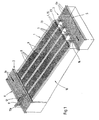
- the picking warehouse for general cargo and especially for food in cardboard containers, that have a very high turnover rate in the wholesale sector primarily from a storage area 1, a storage area 1 upstream Assembly area 2 and a picking area downstream of the storage area 1 3 together.
- the storage takes place in the assembly area 2 new goods to be stored in the correct storage location within the storage area 1.
- the individual piece goods are accordingly removed from storage area 1 by computer from the Commission and to a place where the compilation and if necessary The commissions are packaged into larger packaging containers.
- Removal of the individual goods from storage area 1 are removal devices 4 provided that the goods removed from the storage area 1 individually place on a transport path 5, along which the further transport of the Goods done.
- the goods in the assembly area 2 are also conveyed by means of a continuously driven conveyor track 6, which, like the conveyor track 5 in the picking area 3, from a variety of driven Transport rollers 6a composed on which the transported piece goods roll along.
- the storage area 1 is composed of a plurality arranged at a uniform height and parallel aligned lanes 7 together.
- the Warehouse aisles 7 are slightly inclined and descending towards the picking area 3 arranged and consist of roller tracks 8 from freely rotatable rollers or Rollers.
- the individual warehouse aisles 7 are separated by limits 9 so that goods are not accidentally can get into neighboring storage aisles. Every camp aisle is with Provide braking devices with which the rollers or rollers individually or brake in groups so that they roll along the storage aisles Were not reaching too high a speed.
- the rollers can be provided with wheel flanges.
- each warehouse aisle there are 7 in each warehouse aisle only goods or piece goods of the same type. 1 and 2 shown, consisting of a total of four storage aisles 1 therefore four different types of goods can be stored.
- the goods the same type of goods are arranged one behind the other in the respective warehouse aisle 7, whereby they automatically move up to due to the inclination of the roller conveyor 8 move the end of the warehouse aisle 7 facing the picking area 3, and the foremost product is held there at a limit stop 23.
- a total of four storage aisles 7 form together a module 10.
- modules can be arranged side by side be, so that, depending on the spatial conditions, up to one hundred storage aisles side by side and with common facilities of the Arrange assembly area 2 and picking area 3.
- the order picking warehouse shown can also be stacked several times be arranged so as to multiply the space utilization.
- the transport track 6 is common to all storage lanes 7, which is why via the transport track 6 goods of very different types can also be transported.
- Around Classifying goods in the correct warehouse aisle 7 is the one in FIG. 1 illustrated embodiment above the conveyor track 6, a cross conveyor 11 arranged with the conveying direction 12 in the direction of the storage lanes 7.
- the cross conveyor 11 is adjustable along the transport path 6 according to the arrow 11a, and so on to take a position in front of the storage alley 7 to be populated.
- the cross conveyor 11 is arranged with respect to the transport path 6 that about the goods 6 arriving in the third storage lane from the right.
- the cross conveyor 11 is preferably a belt conveyor with a high coefficient of friction, so that goods also cross to the direction of transport the transport path 6 can be moved on the transport rollers 6a.
- the setting of the cross conveyor 11 with respect to the length of the transport path 6 is carried out fully automatically depending on the transport path 6 supplied product group. Their identification can e.g. B. using a barcode take place, which is on the piece goods.
- each storage aisle 7 can be one own, reaching between the transport rollers 6a of the transport path 6 Cross conveyor 13 may be assigned. This can be constructed similarly to the removal device 4th
- the A side of the transport path 6 facing away from storage lanes 7 is a second picking area be arranged so that the transport path 6 on both sides Have the picking areas loaded.
- this Case can also transport the cross conveyor 11, 13 in both directions.
- the goods are picked in the picking area 3 by means of the removal devices 4 taken individually from the storage aisles and onto the common one Conveyed transport path 5, which extends across the storage lanes 7.
- Pollerförrnige Rollers 14 with a horizontal axis of rotation cause a tilt-free Transfer and redirect the goods from the removal device 4 to the Transport lane 5.
- Each individual storage lane 7 is a separate removal device 4 assigned, which is why goods removed from several storage aisles 7 at the same time and can be transferred to the transport track 5.
- Each removal device 4 is composed of a horizontal conveyor 15 and one Lifting mechanism together.
- the horizontal conveyor 15 is located in Extension and alignment to the Lagergasse 7.
- the horizontal conveyor 15 exists from several endless belts guided over pulleys and is enough its rear end 16 viewed in the conveying direction into the respective warehouse aisle 7 in. To enable this overlap of the two transport systems, there can be 8 free spaces between the rollers of the roller conveyor, into which the transport belts of the horizontal conveyor 15 fit.
- the front end 17 of the horizontal conveyor 15 viewed in the conveying direction extends close to the transport track 5, so that a delay-free at this location and gentle transfer of the goods to the transport track 5 achieved is additionally supported by the bollard-shaped rollers shown in FIG. 1 14th
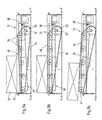
- the in the Figs. 3a to 3d lifting mechanism not shown in detail Removal device 4 serves the horizontal conveyor 15, but at least its effective conveying area to raise.
- the horizontal conveyor 15 pivotable about an axis 18 disposed near its front end 17, whereby the rear end 16 of the horizontal conveyor 15 can be raised.
- Actuation of the lifting mechanism therefore reaches the effective conveying surface of the Horizontal conveyor 15 from the passive position 19 shown in Fig. 3a in the in contrast, raised, active position 19 '. Only in the active position 19 ' engages the conveying surface of the horizontal conveyor 15 from below under that in the storage aisle 7 foremost goods 20 so that they are gripped by the horizontal conveyor 15 and shown in different steps in FIGS. 2b to 2d Way is transferred to the transport path 5.
- the horizontal conveyor 15 is only then driven when it is shown in dashed lines in FIGS. 3a to 3d, active position 19 '. However, the horizontal conveyor 15 is located in the passive position 19, it stands still.
- FIGS. 4a to 4c, 5 and 6 described second embodiment.
- the horizontal conveyor works here 15 in continuous operation, d. H. he runs even when he is at non-actuated lifting mechanism in its lowered, passive position 19 located.
- the horizontal conveyor 15 runs "empty" in this case, and takes the foremost Goods 20 only due to its lifting and contacting the underside the goods 20.
- the advantage of this design option is that the drive of several horizontal conveyors 15 via a common drive shaft can be done.
- This common drive shaft is also the axis 18 around which around the individual horizontal conveyors 15 from the passive position 19 to the active one Position 19 'are pivotable.
- control is therefore carried out of the individual removal devices 4 exclusively by pressing the Lifting mechanism while the actual conveying movement runs continuously. Every time, by controlling the lifting mechanism of the horizontal conveyor 15 moves from its passive to the active position, a single item 20 taken from the respective storage lane 7.
- the second foremost Goods 21 is gripped by the horizontal conveyor 15 is in the range of rear, liftable end 16 of the horizontal conveyor 15 attached a stop 22, against which the second foremost product 21 comes.
- This product 21 can therefore Do not continue to roll on the roller conveyor 8 as long as the horizontal conveyor 15 is in its active position 19 '.
- the stop 22 gives the following Goods 21 free, so that this up to the front limit stop 23rd the Lagergasse 7 can roll forward and is the new front item.
- the limit stop 23 protrudes over the contact surface of the storage lane 7 addition, which is why the horizontal conveyor 15 so far by means of the lifting mechanism can be raised that the conveying surface of the horizontal conveyor 15 above this Limit stop 23 is located.
- FIGS. 3a to 3d the structure of the removal devices show more schematically, are based on the Figs. 4a to 4c, 5 and 6 also explained the construction details of the removal devices:
- the horizontal conveyor 15 of the removal device 4 consists of a first one Pulley 24, the axis of which coincides with the drive shaft 18 and with this is rotatably connected, and a second, more facing the roller conveyor 8 Pulley 25.
- An endless leads over both pulleys 24, 25 Belt 26 with a non-slip surface.
- the pulley 25 is in a housing 27 mounted, which is pivotable about an axis of rotation 28 near the transport path 5 is.
- To partially raise the horizontal conveyor 15 from the in Fig. 4a shown passive position in the active position shown in Fig. 4b and 4c Position is its rear end 16, which reaches the end of the roller conveyor 8 pivotable about the axis of rotation 28.
- the housing 27 pivotable rear pulley 25 from its lower to its higher position, whereby the goods 20 lying against the limit stop 23 by then is gripped from below and transported in the direction of the transport path 5.
- This transport is shown in FIGS. 4b and 4c.
- the stop 22 projects according to Fig. 4c on the conveyor level of the roller conveyor, so that the following Goods 21 initially only reached the stop 22. Now after Lowering the removal device again into the passive one shown in FIG. 4a This item can also be positioned up to the rigid limit stop 23 then roll.
- each the removal devices 4 has its own magnetic coupling 29 which can also be controlled separately from the other magnetic clutches.
- the magnetic clutch 29 surrounds the drive shaft 18 in a ring and is supported by a Articulated lever 30 from below against the housing 27 of the horizontal conveyor 15 In this way, the drive torque of the drive shaft 18 can be via the magnetic coupling 29 convert into a pivoting movement of the articulated lever 30, so that the housing 27 is pivoted about its axis of rotation 28 upwards.
- the Force to lift the horizontal conveyor, including those supported on it Goods 20 is therefore exclusively from the existing rotational movement of the Drive shaft 18 derived.
- the one required for each individual control process additional energy is therefore limited to the relatively low energy of the electric magnetic coupling 29.
- Transmission linkage 31 can be used, which is parallel to the drive shaft 18 extends. In this way it is possible to simultaneously use several articulated levers 30 insert, whereby the housing 27 lift tilt-free leaves. This is particularly advantageous because in the exemplary embodiment each horizontal conveyor 15 to achieve a wide contact area over total has four straps 26.
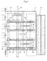
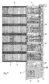
- Fig. 5 shows that the longitudinal axes of the transport rollers 6a of the transport path 5 at an angle ⁇ obliquely to the transport direction of the roller conveyors 8 are arranged. This results in the transportation of the goods along the transport path 5 not only a conveying component in the direction of the transport path itself, but a second funding component away from the storage aisles.
- a commodity or a piece good 32 is shown sequentially in FIG. 5, like this very quickly due to the arrangement of the transport rollers 6a
- the outer edge 33 of the transport path 5 arrives. In this way it is avoided that removed and transported along the transport path 5 piece goods from the subsequent general aisles hinder the emergence of general cargo.
- FIG. 7 arrive incoming piece goods 32 by tilting the transport rollers 6b at the angle ⁇ to that edge 33 of the transport path 6 that is immediately past the warehouse lanes. This ensures that incoming General cargo 32 are always on this edge of the transport path before the piece goods reach the individual warehouse aisles.
- the transport rollers 6a are aligned straight, d. H. aligned with the warehouse aisles.
- the cross conveyor 13 are located between successive transport rollers 6a.
- the driven transport rollers 6a point in the transport direction a sufficient distance from each other.
- the cross conveyor 13 works as well as above for the picking area of the picking warehouse was explained using endless belts 34 that over pulleys 35, 36 are guided.
- the pulleys 35 are driven, via a for all cross conveyor 13 common drive shaft 37.
- the cross conveyor 13 are located in a housing pivotable about an axis of rotation 38 39.
- the axis of rotation 38 is located at the end facing away from the storage aisles of the cross conveyor.
- FIG. 8a this is in its passive position.
- the piece goods 32 roll along of the transport rollers 6a without cross-conveying.
- FIG. 8b With actuation of the cross conveyor raises it according to FIG. 8b, the housing 39 being around the axis of rotation 38 pivots.
- the geometric relationships are such that the effective conveying surface of belt 34 and transport rollers 6a then on same height when the effective conveying surface of the belt 34 and extend the top of the transport rollers 6a exactly parallel to each other. This Case is shown in Fig. 8b. Then, as shown in FIG.
- Such an obstacle may be the flange 41 of the transport rollers 6a.
- the lifting mechanism for pivoting the housing 39 about the axis of rotation 38 works the same as above with reference to FIGS. 3a to 3d and 4a to 4c for the removal devices explained: the drive of all Cross conveyor 13 takes place via the common drive shaft 37, furthermore each has Cross conveyor 13 via its own magnetic coupling 29 for deriving the movement the drive shaft 37 on the pivoting and thus partially lifting of the housing 39 of the cross conveyor.
- each magnetic coupling is 29 Can be controlled separately from the other magnetic clutches, so as to be internal to the system to be able to select that warehouse lane 7 into which those rolling over the transport track 6 General cargo should be sorted.
Abstract
Description
Die Erfindung betrifft ein Kommissionierlager für Stückgüter gemäß Oberbegriff des Anspruchs 1.The invention relates to a picking warehouse for piece goods according to the preamble of claim 1.
Die Kommissionierlagertechnik gewinnt in allen Bereichen des Handels und insbesondere auch im Lebensmittelgroßhandel an Bedeutung. Jedoch büßt die Lagertechnik im engeren Sinne, d. h. die statische Lagerung der einzelnen Stückgüter, eher an Bedeutung ein, wohingegen die dynamischen Prozesse und in erster Linie das Umschlagen der Güter an Bedeutung gewinnen. Ziel einer modernen Lagertechnik ist es daher, die Verweildauer der einzelnen Stückgüter in dem Lager und damit die mit der Einlagerung verbundene Kapitalbildung so gering wie möglich zu halten.The picking warehouse technology wins in all areas of the trade and in particular also important in food wholesale. However, the warehouse technology is penalizing in the narrower sense, d. H. the static storage of the individual piece goods, rather important, whereas the dynamic processes and primarily the handling of goods becomes more important. The aim of modern warehouse technology It is therefore the length of time that the individual piece goods remain in the warehouse and thus the capital formation associated with the storage increases as little as possible hold.
Die bekannten Kommissionierlager sind als mehrstöckige Regalkonstruktionen mit nebeneinander und übereinander angeordneten Lagergassen für die Stückgüter ausgebildet. Die Böden der so gebildeten Lagergassen sind mit Rollenbahnen aus frei drehbaren Rollen versehen und leicht geneigt, so daß die an dem einen Ende der Lagergassen, der sogenannten Beschickungs- oder Bestückungsseite, eingelagerten Waren unter ihrer eigenen Schwerkraft entlang den Rollenbahnen zum anderen Ende der Lagergasse, der Entnahme- bzw. Kommissionierseite, laufen. Die Einlagerung der Stückgüter auf der Beschickungsseite erfolgt in der Regel von Hand, indem die einzelnen Stückgüter von Hand von einer Palette entnommen und in die jeweils zugewiesene Lagergasse eingesetzt werden. Auch das Kommissionieren an der Entnahmeseite des Kommissionierregals erfolgt oftmals noch von Hand; kann aber auch über gesteuerte Entnahmeeinrichtungen erfolgen, siehe z.B CH 432366A.The well-known order-picking warehouse is a multi-storey rack construction side-by-side and stacked aisles for general cargo educated. The floors of the storage aisles thus formed are made of roller conveyors Freely rotatable castors and slightly inclined, so that at one end the storage aisles, the so-called loading or loading side Were under their own gravity along the roller conveyors to the other end of the warehouse aisle, the picking or picking side. The goods are usually stored on the loading side by Hand picked by hand from a pallet of individual piece goods and used in the assigned warehouse aisle. Picking too often takes place on the removal side of the picking rack by hand; can also be done via controlled removal devices, see e.g. CH 432366A.
Bekannt sind jedoch auch rechnergesteuert verfahrbare Entnahmevorrichtungen in Gestalt von Fördergeräten, die in einem auf der Kommissionierseite des Regals angeordneten Gang verfahrbar sind und entsprechend dem Kommissionierauftrag die in den einzelnen Lagergassen vorrätig gehaltenen Stückgüter übernehmen und zu einem Auftrag zusammenstellen. Die hierbei verwendeten Fördereinrichtungen sind über entsprechende Führungen in zwei Koordinaten verfahrbar, so daß von der Fördereinrichtung jede der übereinander und nebeneinander angeordneten Lagergassen einzeln angefahren werden kann.However, computer-controlled removal devices are also known in Shape of conveyors in one on the picking side of the shelf arranged aisle are movable and according to the picking order take over the general cargo held in the individual warehouse aisles and put it together for an order. The funding facilities used here can be moved in two coordinates via corresponding guides, so that each of the conveyors arranged one above the other and side by side Storage lanes can be approached individually.
Der Erfindung liegt die Aufgabe zugrunde, ein Kommissionierlager zu schaffen, mit dem sich hohe Umschlagraten erzielen lassen.The invention has for its object to provide a picking warehouse with which high turnover rates can be achieved.
Zur Lösung wird bei einem Kommissionierlager der eingangs genannten Art vorgeschlagen, daß jede Lagergasse mit einer eigenen, unabhängig von den übrigen Entnahmevorrichtungen betätigbaren Entnahmevorrichtung versehen ist; siehe den Kennzeichen des Anspruch 1.To solve this problem , it is proposed in a picking warehouse of the type mentioned at the outset that each storage aisle is provided with its own removal device which can be operated independently of the other removal devices; see the characteristics of claim 1.
Mit einem so ausgebildeten Kommissionierlager läßt sich eine höhere Umschlagrate erzielen als dies bei bekannten Systemen der Fall ist, da jede einzelne Lagergasse mit einer eigenen Entnahmevorrichtung versehen ist, die unabhängig von den übrigen Entnahmevorrichtungen des Kommissionierlagers rechnergesteuert betätigbar ist. Das erfindungsgemäße Kommissionierlager ermöglicht auf diese Weise eine Umschlaggeschwindigkeit, bei der bei voller Ausnutzung es letztlich sogar möglich wäre, Waren aus sämtlichen Lagergassen gleichzeitig zu entnehmen und zu einem Kommissionsauftrag zusammenzustellen.With a picking warehouse designed in this way, a higher handling rate can be achieved achieve than is the case with known systems, since each individual Lagergasse is provided with its own removal device that is independent Computer-controlled by the other removal devices of the picking warehouse can be actuated. The picking warehouse according to the invention enables this way a turnover speed at which, when fully utilized, it ultimately it would even be possible to remove goods from all warehouse aisles at the same time and put together for a commission order.
Zum Abtransport der mittels der Entnahmevorrichtungen aus den jeweiligen Lagergassen entnommenen Waren wird gemäß einer bevorzugten Ausführungsform des Kommissionierlagers vorgeschlagen, daß sich entlang den Entnahmevorrichtungen und quer zu den Lagergassen eine kontinuierlich angetriebene Transportbahn für die entnommenen Waren erstreckt.For the removal of the removal devices from the respective storage aisles removed goods is according to a preferred embodiment of the picking warehouse suggested that along the picking devices and a continuously driven one across the storage aisles Transport path for the removed goods extends.
Die einzelnen Lagergassen können in an sich bekannter Weise mit geneigten, zu dem Kommissionierbereich hin abfallenden Rollenbahnen aus antriebslosen, frei drehbaren Rollen oder Walzen versehen sein. Die Rollen bzw. Walzen können einzeln oder gruppenweise abbremsbar sein.The individual storage aisles can be inclined in a manner known per se roller conveyors descending towards the picking area from unused, free rotatable rollers or rollers. The rollers or rollers can be braked individually or in groups.
Gemäß einer bevorzugten Ausführungsform setzt sich jede Entnahmevorrichtung aus einem Horizontalförderer und einem eigenen Hubmechanismus zum zumindest teilweisen Anheben des Horizontalförderers zusammen. Der Hubmechanismus bringt im Falle seiner Betätigung den Horizontalförderer in Kontakt mit dem jeweiligen Stückgut, woraufhin dieses dann von dem Horizontalförderer ergriffen und in Richtung auf die nachgeordnete Transporteinrichtung bewegt wird.According to a preferred embodiment, each removal device settles from a horizontal conveyor and its own lifting mechanism at least partial lifting of the horizontal conveyor together. The lifting mechanism brings the horizontal conveyor into contact with the respective piece goods, whereupon this is then taken up by the horizontal conveyor and is moved in the direction of the downstream transport device.
Die Zahl der Antriebselemente und der beweglichen Einzelteile läßt sich reduzieren, indem gemäß einer bevorzugten Weiterbildung der Antrieb einer Mehrzahl der Horizontalförderer über eine gemeinsame Antriebswelle erfolgt, die sich quer zu den Lagergassen erstreckt.The number of drive elements and the moving individual parts can be reduced, by driving a plurality according to a preferred development the horizontal conveyor takes place via a common drive shaft, which is transverse extends to the warehouse aisles.
Desweiteren wird bei einer Ausgestaltung des Kommissionierlagers mit einer aus Rollenbahnen bestehenden Lagergasse vorgeschlagen, daß der Horizontalförderer, mittels des Hubmechanismus bis in eine Höhe anhebbar ist, in der sich die wirksame Förderfläche des Horizontalförderers oberhalb der Aufstandsfläche der Waren auf der Rollenbahn befindet. Auf diese Weise wird vermieden, daß die an vorderster Stelle befindliche Ware in eine undefinierte Stellung im Bereich zwischen der Lagergasse und der Entnahmevorrichtung, d. h. dem Horizontalförderer gelangt.Furthermore, the order picking warehouse is designed with one Existing conveyor alley proposed that the horizontal conveyor, can be raised to a height by means of the lifting mechanism the effective conveying area of the horizontal conveyor above the contact area the goods are on the roller conveyor. In this way it is avoided that the goods in the foremost position in an undefined position in the area between the storage aisle and the removal device, d. H. the horizontal conveyor arrives.
Zur Erzielung eines sicheren Ergreifens des Stückgutes wird weiterhin vorgeschlagen, daß jede Lagergasse an ihrem dem Kommissionierbereich zugewandten Ende mit einem über die Aufstandsfläche für die Waren hinausragenden Begrenzungsanschlag versehen ist, an der die jeweils vorderste Ware anliegt, und daß der Horizontalförderer der Entnahmevorrichtung mittels des Hubmechanismus bis in eine Höhe anhebbar ist, in der sich die wirksame Förderfläche des Horizontalförderers oberhalb des Begrenzungsanschlags befindet. In order to achieve a secure gripping of the piece goods, it is also proposed that that each warehouse aisle facing the picking area End with a limit stop protruding beyond the contact area for the goods is provided, on which the foremost goods are in contact, and that the horizontal conveyor of the removal device by means of the lifting mechanism can be raised to a height at which the effective conveying surface of the horizontal conveyor located above the limit stop.
Um zu verhindern, daß während der Entnahme der vordersten Ware auch die dahinter angeordnete Ware von der Förderbewegung des Horizontalförderers erfaßt wird, ist gemäß einer weiteren Ausgestaltung die Entnahmevorrichtung mit einem der Lagergasse zugewandten und durch Betätigung des Hubmechanismus anhebbaren Anschlag zum vorläufigen Zurückhalten der zweitvordersten Ware versehen. Zur Erzielung einer baulichen Vereinfachung ist es hierbei von Vorteil, wenn der Anschlag zusammen mit dem Horizontalförderer anhebbar gestaltet ist.In order to prevent the goods in front from being removed, even those behind arranged goods detected by the conveying movement of the horizontal conveyor is, according to a further embodiment, the removal device with a facing the warehouse aisle and raised by operating the lifting mechanism Provide a stop to temporarily hold back the second foremost item. In order to achieve a structural simplification, it is advantageous here if the stop is designed to be raised together with the horizontal conveyor.
Zwecks konstruktiv einfacher Realisierung des Hubmechanismus wird ferner vorgeschlagen, daß zum teilweisen Anheben des Horizontalförderers dessen hinteres, in die Lagergasse reichendes Ende um die zugleich eine Drehachse bildende Antriebswelle verschwenkbar ist.For the purpose of constructively simple realization of the lifting mechanism, it is also proposed that that for partially lifting the horizontal conveyor the rear, end reaching into the Lagergasse around the axis of rotation which also forms an axis of rotation Drive shaft is pivotable.
Zur Vermeidung einer eigenen Kraftquelle für das Anheben des Horizontalförderers einschließlich der sich darauf abstützenden Ware wird desweiteren ein Weg vorgeschlagen, die hierzu erforderliche Kraft unmittelbar von der ohnehin vorhandenen Drehbewegung der gemeinsamen Antriebswelle abzuleiten. Hierzu ist eine bevorzugte Ausgestaltung gekennzeichnet durch eine Magnetkupplung zum Ableiten der Bewegung beim zumindest teilweisen Anheben des Horizontalförderers aus der Drehbewegung der gemeinsamen Antriebswelle, wobei die Magnetkupplung jeder Entnahmevorrichtung getrennt von den übrigen Magnetkupplungen ansteuerbar ist. Der Vorteil dieser Ausgestaltung besteht darin, daß zur Betätigung des Hubmechanismus nur der relativ geringe Strom für die elektrische Magnetkupplung aufgebracht werden muß. Die erforderliche Anhebekraft hingegen wird unter Nutzung der Kupplung von dem Antriebsmoment der gemeinsamen Antriebswelle abgeleitet.To avoid having your own power source for lifting the horizontal conveyor including the goods based on it, will also become a way proposed that the force required for this directly from the already existing Derive rotary motion of the common drive shaft. This is a preferred embodiment characterized by a magnetic coupling for deriving the movement when the horizontal conveyor is at least partially raised from the rotary motion of the common drive shaft, the magnetic coupling each removal device can be controlled separately from the other magnetic couplings is. The advantage of this configuration is that for actuation the lifting mechanism only the relatively low current for the electric magnetic coupling must be applied. The required lifting force, however, will using the clutch from the drive torque of the common drive shaft derived.
Vorzugsweise umschließt die Magnetkupplung die Antriebswelle ringförmig, und sie stützt sich über einen Gelenkhebel von unten gegen das Gehäuse des Horizontalförderers ab.The magnetic coupling preferably surrounds the drive shaft in a ring shape, and it is supported by an articulated lever from below against the housing of the horizontal conveyor from.
Mit der Erfindung wird ferner eine in dem Bestückungsbereich quer zu den Lagergassen sich erstreckende, kontinuierlich angetriebene und sich aus einzelnen Transportwalzen zusammensetzende Transportbahn für neu einzulagernde Waren vorgeschlagen. With the invention also one in the assembly area transversely to the storage aisles extending, continuously driven and made up of individual Transport track for transporting goods to be put together proposed.
Diese Transportbahn ist mehreren Lagergassen zugleich zugewiesen. Um die auf der Transportbahn bewegten Stückgüter in die jeweils richtige Lagergasse zu fördern, ist eine weitere Ausgestaltung durch zwischen den Transportwalzen angeordnete, für jede Lagergasse getrennt betätigbare Querförderer mit Förderrichtung in Richtung zu der jeweiligen Lagergasse gekennzeichnet.This transport track is assigned to several storage aisles at the same time. To the on conveying general cargo moving on the transport track to the correct warehouse aisle, is a further embodiment by arranged between the transport rollers, Cross conveyors with conveying direction that can be operated separately for each storage aisle marked towards the respective warehouse lane.
Gemäß einer weiteren Ausgestaltung ist jeder Querförderer mit einem eigenen Hubmechanismus zum zumindest teilweisen Anheben des Querförderers versehen, wobei sich die wirksame Förderfläche des Querförderers bei unbetätigtem Hubmechanismus unterhalb und bei betätigtem Hubmechanismus zumindest teilweise oberhalb der Oberseite der Transportwalzen befindet.According to a further embodiment, each cross conveyor has its own Provide lifting mechanism for at least partially lifting the cross conveyor, the effective conveying surface of the cross conveyor when not actuated Lifting mechanism below and at least partially when the lifting mechanism is actuated located above the top of the transport rollers.
Um zum Anheben des Querförderers einschließlich der gegebenenfalls erheblichen Gewichtskraft des darüber befindlichen Stückgutes einen eigenen Antrieb zu benötigen, kann die Hubkraft auch von der Antriebsenergie für die Querförderer abgeleitet werden. Hierzu wird vorgeschlagen, daß der Antrieb einer Mehrzahl der Querförderer über eine gemeinsame Antriebswelle erfolgt, und daß jeder Querförderer über eine eigene Magnetkupplung zum Ableiten der Bewegung beim zumindest teilweisen Anheben des Querförderers aus der Drehbewegung der gemeinsamen Antriebswelle verfügt, wobei die Magnetkupplung jedes Querförderers getrennt von den übrigen Magnetkupplungen ansteuerbar ist.To raise the cross conveyor including any significant Weight of the piece goods above it to its own drive the lifting force can also require the drive energy for the cross conveyor be derived. For this purpose, it is proposed that the drive of a plurality of Cross conveyor via a common drive shaft, and that each cross conveyor via its own magnetic coupling to derive the movement at least partial lifting of the cross conveyor from the rotational movement of the common Drive shaft has, the magnetic coupling of each cross conveyor separately can be controlled by the other magnetic clutches.
Schließlich wird vorgeschlagen, daß sich die Transportbahn aus Transportwalzen zusammensetzt, deren wirksame Breite mindestens das Doppelte der Breite der Rollen bzw. Walzen der Rollenbahn beträgt, und daß die Längsachsen der Transportwalzen unter einem Winkel schräg zur Richtung der Lagergassen mit Förderkomponente weg von den Lagergassen angeordnet sind.Finally, it is proposed that the transport path consist of transport rollers the effective width of which is at least twice the width of the Rolls or rolls of the roller conveyor, and that the longitudinal axes of the transport rollers at an angle to the direction of the storage aisles with the conveyor component are arranged away from the storage aisles.
Nachfolgend wird ein erfindungsgemäßes Kommissionierlager anhand von Ausführungsbeispielen und unter Bezugnahme auf die Zeichnungen erläutert. Auf den Zeichnungen zeigen:
- Fig. 1
- in perspektivischer Darstellung einen Teil eines Kommissionierlagers in einer ersten Ausführungsform;
- Fig. 2
- in perspektivischer Darstellung einen Teil eines Kommissionierlagers in einer zweiten Ausführungsform;
- Fig. 3a
- einen Teilschnitt durch das Kommissionierlager in jenem Bereich, in dem die einzelnen Waren mittels einer Entnahmevorrichtung aus Lagergassen des Lagerbereichs entnommen werden, wobei die Entnahmevorrichtung in ihrer unbetätigten Stellung gezeigt ist;
- Fig. 3b
- entspricht der Darstellung nach Fig. 3a, jedoch bei betätigter Entnahmevorrichtung;
- Fig. 3c
- entspricht der Fig. 3b, jedoch bei im Vergleich zu Fig. 3b zeitlich fortgeschrittener Funktion und
- Fig. 3d
- entspricht der Darstellung nach Fig. 3c, jedoch bei wiederum zeitlich fortgeschrittener Funktion;
- Fig. 4a
- einen gegenüber Fig. 3a konstruktiv abgewandelten Teilschnitt durch das Kommissionierlager in jenem Bereich, in dem die einzelnen Waren mittels einer Entnahmevorrichtung aus Lagergassen des Lagerbereichs entnommen werden, wobei die Entnahmevorrichtung in ihrer unbetätigten Stellung gezeigt ist;
- Fig. 4b
- entspricht der Darstellung nach Fig. 4a, jedoch bei betätigter Entnahmevorrichtung;
- Fig. 4c
- entspricht der Fig. 4b, jedoch bei im Vergleich zu Fig. 4b zeitlich fortgeschrittener Funktion;
- Fig. 5
- eine teilweise Draufsicht auf das Kommissionierlager nach Fig. 2 im Bereich der Entnahmevorrichtungen;
- Fig. 6
- eine vergrößerte Darstellung des Details VI in Fig. 5;
- Fig. 7
- eine Draufsicht auf einen Teil des Kommissionierlagers nach Fig. 2 im Bestückungsbereich;
- Fig. 8a
- einen Teilschnitt durch das Kommissionierlager im Bestückungsbereich, wobei ein dort angeordneter Querförderer in unbetätigter Stellung gezeigt ist;
- Fig. 8b
- entspricht der Darstellung nach Fig. 8a, jedoch bei betätigtem Querförderer und
- Fig. 8c
- entspricht der Fig. 8b, jedoch bei im Vergleich zu Fig. 8b zeitlich fortgeschrittener Funktion.
- Fig. 1
- a perspective view of part of a picking warehouse in a first embodiment;
- Fig. 2
- a perspective view of part of a picking warehouse in a second embodiment;
- Fig. 3a
- a partial section through the picking warehouse in that area in which the individual goods are removed from the aisles of the storage area by means of a removal device, the removal device being shown in its unactuated position;
- Fig. 3b
- corresponds to the representation according to FIG. 3a, but with the removal device actuated;
- Fig. 3c
- corresponds to FIG. 3b, but with function and advanced in time compared to FIG. 3b
- Fig. 3d
- corresponds to the representation according to FIG. 3c, but with a function that is again more advanced in time;
- Fig. 4a
- a constructively modified partial section through FIG. 3a through the picking warehouse in the area in which the individual goods are removed from the aisles of the storage area by means of a removal device, the removal device being shown in its unactuated position;
- Fig. 4b
- corresponds to the representation according to FIG. 4a, but with the removal device actuated;
- Fig. 4c
- corresponds to FIG. 4b, but with a function that is more advanced in time than FIG. 4b;
- Fig. 5
- a partial plan view of the picking warehouse of Figure 2 in the area of the removal devices.
- Fig. 6
- an enlarged view of the detail VI in Fig. 5;
- Fig. 7
- a plan view of a part of the picking warehouse of Figure 2 in the loading area.
- Fig. 8a
- a partial section through the picking warehouse in the loading area, a transverse conveyor arranged there being shown in the unactuated position;
- Fig. 8b
- corresponds to the representation of Fig. 8a, but with the cross conveyor and operated
- Fig. 8c
- corresponds to FIG. 8b, but with a function that is more advanced in time than FIG. 8b.
Das Kommissionierlager für Stückgüter und insbesondere für Lebensmittel in Kartongebinden,
die im Großhandel eine sehr hohe Umschlagrate haben, setzt sich in
erster Linie aus einem Lagerbereich 1, einem dem Lagerbereich 1 vorgeschalteten
Bestückungsbereich 2 und einem dem Lagerbereich 1 nachgeschalteten Kommissionierbereich
3 zusammen. In dem Bestückungsbereich 2 erfolgt die Einlagerung
neu einzulagernder Stückgüter in den richtigen Lagerort innerhalb des Lagerbereiches
1. In dem Kommissionierbereich 3 werden die einzelnen Stückgüter entsprechend
der Kommission rechnergesteuert aus dem Lagerbereich 1 entnommen und
an einen Ort gefördert, an dem dann die Zusammenstellung und gegebenenfalls
Verpackung der Kommissionen zu größeren Verpackungsgebinden erfolgt. Zur
Entnahme der einzelnen Waren aus dem Lagerbereich 1 sind Entnahmevorrichtungen
4 vorgesehen, die die aus dem Lagerbereich 1 einzeln entnommenen Waren
auf eine Transportbahn 5 ablegen, entlang der dann der Weitertransport der
Waren erfolgt.The picking warehouse for general cargo and especially for food in cardboard containers,
that have a very high turnover rate in the wholesale sector
primarily from a storage area 1, a storage area 1
Auch die Zuförderung der Waren im Bestückungsbereich 2 erfolgt mittels einer
kontinuierlich angetriebenen Transportbahn 6, die sich, ebenso wie die Transportbahn
5 in dem Kommissionierbereich 3, aus einer Vielzahl angetriebener
Transportwalzen 6a zusammensetzt, auf denen die transportierten Stückgüter
entlangrollen.The goods in the
Der Lagerbereich 1 setzt sich aus einer Mehrzahl in einheitlicher Höhe angeordneter
und parallel zueinander ausgerichteter Lagergassen 7 zusammen. Die
Lagergassen 7 sind leicht geneigt und zu dem Kommissionierbereich 3 hin abfallend
angeordnet und bestehen aus Rollenbahnen 8 aus frei drehbaren Rollen oder
Walzen. Infolge der leichten Neigung der Lagergassen 7 können die darin befindlichen
Waren unter Wirkung ihres eigenen Gewichts entlang der jeweiligen Lagergasse
7 entlangrollen, bis sie auf ein Hindernis stoßen. Die einzelnen Lagergassen
7 sind durch Begrenzungen 9 voneinander getrennt, so daß Waren nicht versehentlich
in benachbarte Lagergassen gelangen können. Jede Lagergasse ist mit
Bremseinrichtungen versehen, mit denen sich die Rollen oder Walzen einzeln oder
gruppenweise abbremsen lassen, damit die entlang der Lagergassen entlangrollenden
Waren keine zu große Geschwindigkeit erreichen. Zur seitlichen Führung
der Waren können die Rollen bzw. Walzen mit Spurkränzen versehen sein.The storage area 1 is composed of a plurality arranged at a uniform height
and parallel aligned
Bei dem beschriebenen Kommissionierlager befinden sich in jeder Lagergasse 7
ausschließlich Waren bzw. Stückgüter derselben Art. Bei dem in den Fign. 1 und 2
dargestellten, aus insgesamt vier Lagergassen bestehenden Lagerbereich 1 ist
daher eine Lagerung von vier unterschiedlichen Warenarten möglich. Die Waren
derselben Warenart sind hintereinanderliegend in der jeweiligen Lagergasse 7 angeordnet,
wobei sie sich infolge der Neigung der Rollenbahn 8 selbsttätig bis an
das dem Kommissionierbereich 3 zugewandte Ende der Lagergasse 7 bewegen,
und die vorderste Ware dort an einem Begrenzungsanschlag 23 festgehalten wird.In the order picking warehouse described, there are 7 in each warehouse aisle
only goods or piece goods of the same type. 1 and 2
shown, consisting of a total of four storage aisles 1
therefore four different types of goods can be stored. The goods
the same type of goods are arranged one behind the other in the
Die in den Fign. 1 und 2 dargestellten insgesamt vier Lagergassen 7 bilden gemeinsam
ein Modul 10. Mehrere solcher Module können nebeneinander angeordnet
werden, so daß sich, abhängig von den räumlichen Gegebenheiten, bis zu
einhundert Lagergassen nebeneinander und mit gemeinsamen Einrichtungen des
Bestückungsbereiches 2 und des Kommissionierbereiches 3 anordnen lassen.
Zusätzlich kann das dargestellte Kommissionierlager auch mehrfach übereinander
angeordnet sein, um so eine Vervielfachung der Platzausnutzung zu erreichen.The in Figs. 1 and 2, a total of four
Die Transportbahn 6 ist allen Lagergassen 7 gemeinsam, weshalb über die Transportbahn
6 auch Waren sehr unterschiedlicher Art herangefördert werden. Um diese
Waren in die jeweils richtige Lagergasse 7 einzuordnen, ist bei dem in Fig. 1
dargestellten Ausführungsbeispiel über der Transportbahn 6 ein Querförderer 11
mit Förderrichtung 12 in Richtung auf die Lagergassen 7 angeordnet. Der Querförderer
11 ist gemäß dem Pfeil 11a entlang der Transportbahn 6 einstellbar, um so
eine Position vor der jeweils zu bestückenden Lagergasse 7 einzunehmen. In Fig.
1 ist der Querförderer 11 so bezüglich der Transportbahn 6 angeordnet, daß über
die Transportbahn 6 ankommende Waren in die dritte Lagergasse von rechts gelangen.
Bei dem Querförderer 11 handelt es sich vorzugsweise um einen Bandförderer
mit hohem Reibbeiwert, so daß Waren auch quer zu der Transportrichtung
der Transportbahn 6 auf deren Transportwalzen 6a verschoben werden können.
Die Einstellung des Querförderers 11 in bezug auf die Länge der Transportbahn 6
erfolgt vollautomatisch in Abhängigkeit von der jeweils über die Transportbahn 6
zugeführten Warengruppe. Deren Identifizierung kann z. B. anhand eines Barcodes
erfolgen, der sich auf den Stückgütern befindet.The
Gemäß der Ausführungsform nach Fig. 2 kann aber auch jeder Lagergasse 7 ein
eigener, bis zwischen die Transportwalzen 6a der Transportbahn 6 reichender
Querförderer 13 zugeordnet sein. Dieser kann ähnlich aufgebaut sein wie die Entnahmevorrichtung
4.According to the embodiment according to FIG. 2, however, each
Femer kann, was die Fign. 1 und 2 nicht erkennen lassen, auf der anderen, den
Lagergassen 7 abgewandten Seite der Transportbahn 6 ein zweiter Kommissionierbereich
angeordnet sein, so daß sich über die Transportbahn 6 beidseitig
Kommissionierbereiche beschicken lassen. Selbstverständlich sollten in diesem
Fall auch die Querförderer 11, 13 in beiden Richtungen transportieren können.Furthermore, what the FIGS. 1 and 2 do not show on the other, the
A side of the
In dem Kommissionierbereich 3 werden die Waren mittels der Entnahmevorrichtungen
4 einzeln aus den Lagergassen entnommen und auf die gemeinsame
Transportbahn 5 überführt, die sich quer zu den Lagergassen 7 erstreckt. Pollerförrnige
Rollen 14 mit horizontaler Drehachse bewirken ein verkantungsfreies
Überführen und Umlenken der Waren von der Entnahmevorrichtung 4 auf die
Transportbahn 5. Jeder einzelnen Lagergasse 7 ist eine eigene Entnahmevorrichtung
4 zugeordnet, weshalb Waren zugleich aus mehreren Lagergassen 7 entnommen
und auf die Transportbahn 5 überführt werden können.The goods are picked in the picking
Einzelheiten und Funktionsweise der Entnahmevorrichtungen 4 werden nachfolgend
anhand der Figuren 3a bis 3d erläutert.Details and operation of the
Jede Entnahmevorrichtung 4 setzt sich aus einem Horizontalförderer 15 und einem
Hubmechanismus zusammen. Der Horizontalförderer 15 befindet sich in
Verlängerung und Fluchtung zu der Lagergasse 7. Der Horizontalförderer 15 besteht
aus mehreren über Umlenkrollen geführten, endlosen Riemen und reicht mit
seinem in Förderrichtung betrachtet hinteren Ende 16 bis in die jeweilige Lagergasse
7 hinein. Um diese Überschneidung der beiden Transportsysteme zu ermöglichen,
können sich zwischen den Rollen der Rollenbahn 8 Freiräume befinden,
in die die Transportriemen des Horizontalförderers 15 hineinpassen.Each
Das in Förderrichtung betrachtet vordere Ende 17 des Horizontalförderers 15
reicht bis nahe an die Transportbahn 5, so daß an diesem Ort eine verzögerungsfreie
und schonende Übergabe der Waren auf die Transportbahn 5 erreicht
wird, zusätzlich unterstützt durch die in Fig. 1 dargestellten pollerförmigen Rollen
14.The
Der in den Fign. 3a bis 3d nicht im einzelnen dargestellte Hubmechanismus der
Entnahmevorrichtung 4 dient dazu, den Horizontalförderer 15, zumindest aber
dessen wirksame Förderfläche, anzuheben. Hierzu ist der Horizontalförderer 15
um eine nahe seinem vorderen Ende 17 angeordnete Achse 18 schwenkbar, wodurch
sich das hintere Ende 16 des Horizontalförderers 15 anheben läßt. Durch
Betätigung des Hubmechanismus gelangt daher die wirksame Förderfläche des
Horizontalförderers 15 aus der in Fig. 3a dargestellten passiven Stellung 19 in die
demgegenüber angehobene, aktive Stellung 19'. Nur in der aktiven Stellung 19'
greift die Förderfläche des Horizontalförderers 15 von unten unter die in der Lagergasse
7 vorderste Ware 20, so daß diese von dem Horizontalförderer 15 ergriffen
und in der in den Figuren 2b bis 2d in verschiedenen Schritten dargestellten
Weise auf die Transportbahn 5 übergeben wird.The in the Figs. 3a to 3d lifting mechanism not shown in
Für den Antrieb des Horizontalförderers bestehen zwei Ausführungsmöglichkeiten.
Bei der ersten Ausführungsmöglichkeit wird der Horizontalförderer 15 nur dann
angetrieben, wenn er sich in der in den Figuren 3a bis 3d jeweils gestrichelt dargestellten,
aktiven Stellung 19' befindet. Befindet sich der Horizontalförderer 15 hingegen
in der passiven Stellung 19, steht er still.There are two design options for driving the horizontal conveyor.
In the first embodiment, the
Bevorzugt wird demgegenüber jedoch eine nachfolgend anhand der Fign. 4a bis
4c, 5 und 6 beschriebene zweite Ausführungsmöglichkeit. Hierbei arbeitet der Horizontalförderer
15 im Dauerbetrieb, d. h. er läuft selbst dann, wenn er sich bei
nicht betätigtem Hubmechanismus in seiner abgesenkten, passiven Stellung 19
befindet. Der Horizontalförderer 15 läuft in diesem Fall "leer", und ergreift die vorderste
Ware 20 erst infolge seines Anhebens und In-Kontaktbringens mit der Unterseite
der Ware 20. Der Vorteil dieser Ausführungsmöglichkeit besteht darin, daß
der Antrieb mehrerer Horizontalförderer 15 über eine gemeinsame Antriebswelle
erfolgen kann. Diese gemeinsame Antriebswelle ist zugleich die Achse 18, um die
herum die einzelnen Horizontalförderer 15 von der passiven Stellung 19 in die aktive
Stellung 19' schwenkbar sind. Bei dieser Variante erfolgt daher die Ansteuerung
der einzelnen Entnahmevorrichtungen 4 ausschließlich durch Betätigung des
Hubmechanismus, während die eigentliche Förderbewegung ununterbrochen läuft.
Jedesmal, wenn durch Ansteuerung des Hubmechanismus der Horizontalförderer
15 aus seiner passiven in die aktive Stellung gelangt, wird eine einzelne Ware 20
aus der jeweiligen Lagergasse 7 entnommen.In contrast, however, a one based on FIGS. 4a to
4c, 5 and 6 described second embodiment. The horizontal conveyor works here
15 in continuous operation, d. H. he runs even when he is at
non-actuated lifting mechanism in its lowered,
Um zu verhindern, daß zusammen mit der vordersten Ware 20 auch die zweitvorderste
Ware 21 von dem Horizontalförderer 15 ergriffen wird, ist im Bereich des
hinteren, anhebbaren Endes 16 des Horizontalförderers 15 ein Anschlag 22 befestigt,
gegen den die zweitvorderste Ware 21 gelangt. Diese Ware 21 kann daher
auf der Rollenbahn 8 solange nicht weiterrollen, wie sich der Horizontalförderer 15
in seiner aktiven Stellung 19' befindet.To prevent that, together with the
Sobald sich nach Übergabe der vordersten Ware 20 der Horizontalförderer 15
wieder in seine passive Stellung 19 absenkt, gibt der Anschlag 22 die nachfolgende
Ware 21 frei, so daß diese bis an den vorderen Begrenzungsanschlag 23
der Lagergasse 7 vorrollen kann und damit die neue vorderste Ware ist.As soon as the
Der Begrenzungsanschlag 23 ragt über die Aufstandsfläche der Lagergasse 7
hinaus, weshalb der Horizontalförderer 15 mittels des Hubmechanismus soweit
anhebbar ist, daß sich die Förderfläche des Horizontalförderers 15 oberhalb dieses
Begrenzungsanschlages 23 befindet.The
Während die voranstehend erläuterten Fign. 3a bis 3d den Aufbau der Entnahmevorrichtungen eher schematisch zeigen, werden nachfolgend anhand der Fign. 4a bis 4c, 5 und 6 auch konstruktive Einzelheiten der Entnahmevorrichtungen erläutert:While the above-explained FIGS. 3a to 3d the structure of the removal devices show more schematically, are based on the Figs. 4a to 4c, 5 and 6 also explained the construction details of the removal devices:
Der Horizontalförderer 15 der Entnahmevorrichtung 4 besteht aus einer ersten
Riemenscheibe 24, deren Achse mit der Antriebswelle 18 zusammenfällt und mit
dieser drehfest verbunden ist, sowie einer zweiten, mehr der Rollenbahn 8 zugewandten
Riemenscheibe 25. Über beiden Riemenscheiben 24, 25 führt ein endloser
Riemen 26 mit griffiger Oberfläche. Die Riemenscheibe 25 ist in einem Gehäuse
27 gelagert, welches um eine Drehachse 28 nahe der Transportbahn 5 verschwenkbar
ist. Zum teilweisen Anheben des Horizontalförderers 15 aus der in
Fig. 4a dargestellten passiven Stellung in die in Fig. 4b und 4c dargestellte aktive
Stellung ist dessen hinteres, an das Ende der Rollenbahn 8 reichendes Ende 16
um die Drehachse 28 verschwenkbar. Hierbei gelangt die mit dem Gehäuse 27
verschwenkbare hintere Riemenscheibe 25 von ihrer tieferen in ihre höhere Position,
wodurch die bis dahin an dem Begrenzungsanschlag 23 anliegende Ware 20
von unten ergriffen und in Richtung auf die Transportbahn 5 transportiert wird.
Dieser Transport ist in den Fign. 4b und 4c dargestellt. Zu erkennen ist ferner der
an dem Gehäuse 27 der Entnahmevorrichtung ausgebildete Anschlag 22, welcher
verhindert, daß zusammen mit der vordersten Ware 20 auch die zweitvorderste
Ware 21 von dem Horizontalförderer 15 ergriffen wird. Der Anschlag 22 ragt gemäß
Fig. 4c über die Förderebene der Rollentransportbahn, so daß die nachfolgende
Ware 21 zunächst nur bis zu dem Anschlag 22 gelangt. Jetzt, nach dem
erneuten Absenken der Entnahmevorrichtung in die in Fig. 4a dargestellte passive
Stellung kann auch diese Ware bis zu dem starren Begrenzungsanschlag 23
nachrollen.The
Der sich aus den Fign. 4a bis 4c ergebende Hubmechanismus wird unter Verwendung
einer in den Fign. 5 und 6 eingezeichneten Magnetkupplung 29 erreicht. Jede
der Entnahmevorrichtungen 4 verfügt über eine eigene Magnetkupplung 29, die
zudem getrennt von den übrigen Magnetkupplungen ansteuerbar ist. Die Magnetkupplung
29 umschließt ringförmig die Antriebswelle 18 und stützt sich über einen
Gelenkhebel 30 von unten gegen das Gehäuse 27 des Horizontalförderers 15. Auf
diese Weise läßt sich das Antriebsmoment der Antriebswelle 18 über die Magnetkupplung
29 in eine Verschwenkbewegung des Gelenkhebels 30 überführen, so
daß das Gehäuse 27 um seine Drehachse 28 nach oben verschwenkt wird. Die
Kraft zum Anheben des Horizontalförderers einschließlich der sich darauf abstützenden
Ware 20 wird also ausschließlich aus der vorhandenen Drehbewegung der
Antriebswelle 18 abgeleitet. Die für jeden einzelnen Steuerungsvorgang benötigte
zusätzliche Energie beschränkt sich daher auf die relativ geringe Energie der
elektrischen Magnetkupplung 29.The result of the fig. 4a to 4c resulting lifting mechanism is used
one in the fig. 5 and 6 drawn magnetic clutch 29 reached. each
the
Gemäß Fig. 6 kann als Übertragungsglied zwischen der Magnetkupplung 29 und
dem sich von unten gegen den Horizontalförderer 15 legenden Gelenkhebel 30 ein
Übertragungsgestänge 31 verwendet werden, welches sich parallel zu der Antriebswelle
18 erstreckt. Auf diese Weise ist es möglich, zugleich mehrere Gelenkhebel
30 einzusetzen, wodurch sich das Gehäuse 27 verkantungsfrei anheben
läßt. Dies ist insbesondere deshalb von Vorteil, weil bei dem Ausführungsbeispiel
jeder Horizontalförderer 15 zur Erzielung einer breiten Aufstandsfläche über insgesamt
vier Riemen 26 verfügt.6 can be used as a transmission element between the
Fig. 5 läßt erkennen, daß die Längsachsen der Transportwalzen 6a der Transportbahn
5 unter einem Winkel α schräg zur Transportrichtung der Rollenbahnen 8
angeordnet sind. Auf diese Weise ergibt sich beim Transport der Waren entlang
der Transportbahn 5 nicht nur eine Förderkomponente in Richtung der Transportbahn
selbst, sondern eine zweite Förderkomponente weg von den Lagergassen.
Anhand einer Ware bzw. eines Stückgutes 32 ist in Fig. 5 sequentiell dargestellt,
wie dieses in Folge der Anordnung der Transportwalzen 6a sehr schnell an den
Außenrand 33 der Transportbahn 5 gelangt. Auf diese Weise wird vermieden, daß
entnommene und entlang der Transportbahn 5 transportierte Stückgüter aus den
darauffolgenden Lagergassen austretende Stückgüter behindern. Dies erhöht die
Freiheit bei der Kommissionierung, da bei der Ansteuerung der einzelnen Entnahmevorrichtungen
4 nicht berücksichtigt werden muß, ob sich davor gerade andere
Stückgüter befinden. Zu einem reibungsfreien Abtransport der Stückgüter trägt
ferner bei, wenn die wirksame Breite der Transportwalzen 6a mindestens das
doppelte der Breite der Rollen bzw. Walzen der Rollenbahn 8 beträgt.Fig. 5 shows that the longitudinal axes of the
Anhand der Fign. 7 und 8a bis 8c wird nachfolgend erläutert, daß auch im Bestükkungsbereich
des Kommissionierlagers Fördereinrichtungen eingesetzt werden,
die den Fördereinrichtungen im Kommissionierbereich sehr ähnlich sind. Gemäß
Fig. 7 gelangen ankommende Stückgüter 32 durch Schrägstellung der Transportwalzen
6b unter dem Winkel α an jenen Rand 33 der Transportbahn 6, der unmittelbar
an den Lagergassen vorbeiführt. Hierdurch wird erreicht, daß sich ankommende
Stückgüter 32 stets an diesem Rand der Transportbahn befinden, bevor
die Stückgüter die einzelnen Lagergassen erreichen. Vor den Lagergassen sind
die Transportwalzen 6a jedoch, anders als die Transportwalzen 6b, gerade ausgerichtet,
d. h. in Fluchtung der Lagergassen.Using the figures 7 and 8a to 8c is explained below that also in the assembly area
of the order picking warehouse are used
which are very similar to the conveyor facilities in the picking area. According to
Fig. 7 arrive
Die Querförderer 13 befinden sich zwischen aufeinanderfolgenden Transportwalzen
6a. Hierzu weisen die angetriebenen Transportwalzen 6a in Transportrichtung
einen hinreichend Abstand zueinander auf. Der Querförderer 13 arbeitet, ebenso
wie dies voranstehend für den Kommissionierbereich des Kommissionierlagers
erläutert wurde, unter Verwendung endloser Riemen 34, die über Riemenscheiben
35, 36 geführt sind. Die Riemenscheiben 35 sind angetrieben, und zwar über eine
für sämtliche Querförderer 13 gemeinsame Antriebswelle 37. Auch der Querförderer
13 befindet sind in einem um eine Drehachse 38 verschwenkbaren Gehäuse
39. Die Drehachse 38 befindet sich an dem den Lagergassen abgewandten Ende
des Querförderers.The
Anhand der Fign. 8a, 8b und 8c läßt sich die Funktion des Querförderers 13 verstehen.
In Fig. 8a ist dieser in seiner passiven Lage. Die Stückgüter 32 rollen entlang
der Transportwalzen 6a, ohne daß eine Querförderung erfolgt. Mit Betätigung
des Querförderers hebt dieser gemäß Fig. 8b an, wobei sich das Gehäuse 39 um
die Drehachse 38 verschwenkt. Die geometrischen Verhältnisse sind dergestalt,
daß die wirksame Förderfläche von Riemen 34 und Transportwalzen 6a dann auf
gleicher Höhe liegen, wenn sich die wirksame Förderfläche des Riemens 34 und
die Oberseite der Transportwalzen 6a exakt parallel zueinander erstrecken. Dieser
Fall ist in Fig. 8b darstellt. Anschließend führt, wie Fig. 8c erkennen läßt, das Verschwenken
des Gehäuses 39 dazu, daß sich die wirksame Förderfläche 40 des
Riemens 34 schräg über die Oberseite der Transportwalzen 6a erstreckt, so daß
das jeweilige Stückgut 32 auch über etwaige Hindernisse hinweg in die jeweilige
Lagergasse hineintransportiert wird. Ein solches Hindernis kann der Spurkranz 41
der Transportwalzen 6a sein.Using the figures 8a, 8b and 8c, the function of the
Der Hubmechanismus zum Verschwenken des Gehäuses 39 um die Drehachse
38 funktioniert ebenso, wie voranstehend unter Bezugnahme auf die Fign. 3a bis
3d und 4a bis 4c für die Entnahmevorrichtungen erläutert: Der Antrieb sämtlicher
Querförderer 13 erfolgt über die gemeinsame Antriebswelle 37, ferner verfügt jeder
Querförderer 13 über eine eigene Magnetkupplung 29 zum Ableiten der Bewegung
der Antriebswelle 37 auf das Verschwenken und damit teilweise Anheben
des Gehäuses 39 des Querförderers. Wiederum ist auch jede Magnetkupplung 29
getrennt von den übrigen Magnetkupplungen ansteuerbar, um so systemintern
jene Lagergasse 7 auswählen zu können, in die die über die Transportbahn 6 heranrollenden
Stückgüter einsortiert werden sollen. The lifting mechanism for pivoting the
- 11
- Lagerbereichstorage area
- 22
- Bestückungsbereichassembly area
- 33
- Kommissionierbereichpicking
- 44
- Entnahmevorrichtungremoval device
- 55
- Transportbahntransport path
- 66
- Transportbahntransport path
- 6a6a
- Transportwalzentransport rollers
- 77
- LagergasseLagergasse
- 88th
- Rollenbahnroller conveyor
- 99
- Begrenzungenlimitations
- 1010
- Modulmodule
- 1111
- Querförderercross conveyor
- 11a11a
- Pfeilarrow
- 1212
- Förderrichtungconveying direction
- 1313
- Querförderer αCross conveyor α
- 1414
- pollerförmige Rollebollard-shaped roll
- 1515
- Horizontalfördererhorizontal conveyor
- 1616
- hinteres Ende des Horizontalförderersrear end of the horizontal conveyor
- 1717
- vorderes Ende des Horizontalförderersfront end of the horizontal conveyor
- 1818
- Achse, AntriebswelleAxle, drive shaft
- 1919
- passive Stellungpassive position
- 19'19 '
- aktive Stellungactive position
- 2020
- vorderste Wareforemost commodity
- 2121
- zweitvorderste Waresecond foremost commodity
- 2222
- Anschlagattack
- 2323
- Begrenzungsanschlaglimiting stop
- 2424
- Riemenscheibepulley
- 2525
- Riemenscheibepulley
- 2626
- Riemenbelt
- 2727
- Gehäusecasing
- 2828
- Drehachseaxis of rotation
- 2929
- Magnetkupplungmagnetic coupling
- 3030
- Gelenkhebelarticulated lever
- 3131
- Übertragungsgestängetransmission linkage
- 3232
- Stückgutcargo
- 3333
- Außenrandouter edge
- 3434
- Riemenbelt
- 3535
- Riemenscheibepulley
- 3636
- Riemenscheibepulley
- 3737
- Antriebswelledrive shaft
- 3838
- Drehachseaxis of rotation
- 3939
- Gehäusecasing
- 4040
- Förderflächeconveying surface
- 4141
- Spurkranzflange
- αα
- Anstellwinkel der RollenAngle of attack of the rollers
Claims (18)
- Order-picking store for piece goods, comprisingcharacterized in that a constituent part of each removal apparatus (4), in addition to the horizontal conveyor (15), is a movable stop (22) which is directed towards the storage aisle (7) and is intended for holding back the following articles (21), in that the horizontal conveyor (15) is driven, and in that both the drive movement of the horizontal conveyor (15) and the movement of the stop (22) are derived from the rotary movement of a common drive shaft (18).a storage region (1) with a multiplicity of storage aisles (7) which extend parallel to one another in said storage region, comprise roller conveyors (8) and are intended for articles of the same type in each case,a loading region (2) at one end of the storage aisles (7), with means for introducing new articles into the associated storage aisles (7), andan order-picking region (3) at the other end of the storage aisles (7), with separate removal apparatuses (4) for each storage aisle (7) which are intended for transferring individual articles, in a computer-controlled manner, from the storage aisles (7) onto downstream conveying arrangements, each removal apparatus (4) being provided with a horizontal conveyor (15) for the articles (20) which are to be transported away,
- Order-picking store according to Claim 1, characterized in that a continuous driven transporting path (5) for the removed articles extends along the removal apparatuses (4) and transversely to the storage aisles (7).
- Order-picking store according to Claim 1, characterized in that the rollers of the roller conveyors (8) can be braked individually or in groups.
- Order-picking store according to one of the preceding claims, characterized by a dedicated lifting mechanism for each removal apparatus (4), for at least partially raising the horizontal conveyor (15).
- Order-picking store according to Claim 4, characterized in that the horizontal conveyor (15) can be raised, by means of the lifting mechanism, to a level at which the active conveying surface of the horizontal conveyor (15) is located above the surface on which the articles stand on the roller conveyor (8).
- Order-picking store according to one of Claims 1 to 5, characterized in that a plurality of the removal apparatuses (4) are driven via the common drive shaft (18), which extends transversely to the storage aisles (7).
- Order-picking store according to one of Claims 4 to 6, characterized in that, at its end which is directed towards the order-picking region (3), each storage aisle (7) is provided with a boundary stop (23) which projects beyond the surface on which the articles stand and against which the respectively foremost article (20) butts, and in that the horizontal conveyor (15) of the removal apparatus (4) can be raised, by means of the lifting mechanism, to a level at which the active conveying surface of the horizontal conveyor (15) is located above the boundary stop (23).
- Order-picking store according to Claim 7, characterized in that the stop (22) is configured such that it can be raised together with the horizontal conveyor (15).
- Order-picking store according to one of Claims 4 to 8, characterized in that, for the partial raising of the horizontal conveyor (15), the rear end (16) of the latter, which extends into the storage aisle (7), can be pivoted about an axis of rotation (28).
- Order-picking store according to one of Claims 4 to 9, characterized by a magnetic coupling (29) for deriving the movement, during at least partial raising of the horizontal conveyor (15), from the rotary movement of the common drive shaft (18), it being possible for the magnetic coupling (29) of each removal apparatus (4) to be activated separately from the rest of the magnetic couplings (29).
- Order-picking store according to Claim 10, characterized in that the magnetic coupling (29) encloses the drive shaft (18) in an annular manner and is supported against the housing (27) of the horizontal conveyor (15) from beneath via an articulated lever (30).
- Order-picking store according to one of Claims 1 to 11, characterized in that the horizontal conveyor (15) is made up of a first belt pulley (24), which is connected in a rotationally fixed manner to the drive shaft (18), at least one further, co-running belt pulley (25) and an endless belt (26), which is guided over the belt pulleys (24, 25), the driven belt pulley (24) defining the front end (17), and the co-running belt (25) defining the rear end (16), of the horizontal conveyor (15).
- Order-picking store according to one of the preceding claims, characterized by a continuously driven transporting path (6) which extends in the loading region (2), transversely to the storage aisles (7), is made up of individual transporting rollers (6a) and is intended for new articles which are to be introduced.
- Order-picking store according to Claim 13, characterized by transverse conveyors (13) which are arranged between the transporting rollers (6a), can be actuated separately for each storage aisle (7) and have the conveying direction (12) running in the direction of the respective storage aisle (7).
- Order-picking store according to Claim 14, characterized in that each transverse conveyor (13) is provided with a dedicated lifting mechanism for at least partially raising the transverse conveyor, the active conveying surface (40) of the transverse conveyor being located beneath the top side of the transporting rollers (6a) when the lifting mechanism is not actuated and being located at least partially above the top side of the transporting rollers (6a) when the lifting mechanism is actuated.
- Order-picking store according to Claim 15, characterized in that the transverse conveyor (13) is made up of a plurality of belt pulleys (35, 36) over which an endless belt (34) is guided, the top side of the latter forming the active conveying surface (40) of the transverse conveyor (13).
- Order-picking store according to Claim 15 or Claim 16, characterized in that a plurality of the transverse conveyors (13) are driven via a common drive shaft (37), and in that each transverse conveyor (13) has a dedicated magnetic coupling (29) for deriving the movement, during at least partial raising of the transverse conveyor, from the rotary movement of the common drive shaft (37), it being possible for the magnetic coupling (29) of each transverse conveyor (13) to be activated separately from the rest of the magnetic couplings (29).
- Order-picking store according to Claim 2, characterized in that the transporting path (5) is made up of transporting rollers, of which the effective width is at least double the width of the rollers of the roller conveyor (8), and in that the longitudinal axes of the transporting rollers are arranged at an oblique angle (α) to the direction of the storage aisles (7), with a conveying component in the direction away from the storage aisles (7).
Applications Claiming Priority (2)
| Application Number | Priority Date | Filing Date | Title |
|---|---|---|---|
| DE19823083A DE19823083A1 (en) | 1998-05-22 | 1998-05-22 | Dispatch holding unit for food wholesale warehouse has a series of |
| DE19823083 | 1998-05-22 |
Publications (3)
| Publication Number | Publication Date |
|---|---|
| EP0965543A2 EP0965543A2 (en) | 1999-12-22 |
| EP0965543A3 EP0965543A3 (en) | 2001-09-26 |
| EP0965543B1 true EP0965543B1 (en) | 2003-08-06 |
Family
ID=7868708
Family Applications (1)
| Application Number | Title | Priority Date | Filing Date |
|---|---|---|---|
| EP99107698A Expired - Lifetime EP0965543B1 (en) | 1998-05-22 | 1999-04-17 | Dispensing store for piece goods |
Country Status (6)
| Country | Link |
|---|---|
| US (1) | US6186724B1 (en) |
| EP (1) | EP0965543B1 (en) |
| AT (1) | ATE246652T1 (en) |
| DE (2) | DE19823083A1 (en) |
| DK (1) | DK0965543T3 (en) |
| ES (1) | ES2204024T3 (en) |
Families Citing this family (25)
| Publication number | Priority date | Publication date | Assignee | Title |
|---|---|---|---|---|
| DE19905967B4 (en) * | 1999-02-12 | 2004-02-05 | Dynamic Systems Engineering B.V. | System for order picking, in particular for order picking of food in rectangular package containers |
| DE10020608A1 (en) * | 2000-04-27 | 2001-10-31 | Dynamic Systems Engineering B | Storage and / or transport device for piece goods |
| ES2166330B1 (en) * | 2000-05-17 | 2003-02-16 | Gomez Gines Sanchez | OPTIMIZED AUTOMATIC WAREHOUSE. |
| US6615104B2 (en) | 2001-05-01 | 2003-09-02 | Nintendo Of America, Inc. | System and method of selecting box size |
| NO20020585L (en) * | 2002-02-05 | 2003-08-06 | Zopa As | System and method for transferring products from a storage area to a delivery area |
| US7184855B2 (en) * | 2002-03-13 | 2007-02-27 | Stingel Iii Frederick J | Automated container storage and delivery system |
| US6729836B2 (en) * | 2002-03-13 | 2004-05-04 | Stingel, Iii Frederick J. | Automated container storage and delivery system |
| US6871116B2 (en) * | 2002-10-17 | 2005-03-22 | Vertique, Inc. | Determining pallet case configurations for placement by a robot |
| DE102004046439A1 (en) * | 2004-09-24 | 2006-04-06 | Siemens Ag | Device for loading and unloading of load carriers or piece goods |
| US7331440B2 (en) * | 2004-10-26 | 2008-02-19 | Lafontaine Daniel R | Automated order mixing system |
| AT501825B1 (en) * | 2005-05-11 | 2007-03-15 | Sticht Fertigungstech Stiwa | CONVEYOR SYSTEM FOR PROMOTING AND UNIFYING PARTS |
| NL1030328C2 (en) * | 2005-11-01 | 2007-05-03 | Trm Patenten B V | System for arranging and / or storing objects. |
| DE102006048345A1 (en) * | 2006-10-12 | 2008-04-17 | Köra-Packmat Maschinenbau GmbH | Transport method for delivering product i.e. phone-prepaid-card, on conveyor belt, involves shifting product buffers to deliver products on belt for emptying buffers, and emptying one of buffers during filling of other buffers |
| US7963384B2 (en) * | 2008-12-19 | 2011-06-21 | 3584925 Canada Inc. | Automated order sequencing method and system |
| US8540038B1 (en) | 2009-01-09 | 2013-09-24 | The United States Of America As Represented By The Secretary Of The Navy | Low profile omnidirectional vehicle |
| DE102011106667A1 (en) | 2011-07-05 | 2013-01-10 | SSI Schäfer Noell GmbH Lager- und Systemtechnik | Storage and picking system and method for automated order picking with a channel warehouse |
| US20130062160A1 (en) * | 2011-09-14 | 2013-03-14 | Jeffrey J. Steinbach | Article tray and handling of articles with the tray |
| DE102012101267A1 (en) * | 2012-02-17 | 2013-08-22 | Wincor Nixdorf International Gmbh | POS system arrangement |
| CN104289449B (en) * | 2013-07-19 | 2019-10-18 | 李斌云 | Universal sorting platform |
| ITVI20130214A1 (en) * | 2013-08-09 | 2015-02-10 | Idea Srl | AUTOMATED WAREHOUSE |
| DE102015213195A1 (en) * | 2015-07-14 | 2017-01-19 | Siemens Aktiengesellschaft | Transport chute with drive means |
| FI20185415A1 (en) * | 2018-05-04 | 2019-11-05 | Actiw Oy | Grouping station for grouping pallets |
| FR3096364B1 (en) * | 2019-05-23 | 2021-10-29 | Savoye | Process for processing a list of orders in an order picking system, and the corresponding picking station. |
| CN112634541A (en) * | 2020-12-18 | 2021-04-09 | 广州卓腾科技有限公司 | Leather sheath sending device for vehicle management self-service equipment |
| DE102021124545A1 (en) | 2021-09-22 | 2023-03-23 | Stöcklin Logistik Ag | Device and method for sequencing loading units in a predetermined order |
Family Cites Families (12)
| Publication number | Priority date | Publication date | Assignee | Title |
|---|---|---|---|---|
| US3108677A (en) * | 1960-11-25 | 1963-10-29 | Baker Perkins Inc | Pan transfer apparatus |
| CH432366A (en) * | 1963-04-02 | 1967-03-15 | Electrolux Ab | Storage arrangement |
| DE1243106B (en) * | 1964-01-27 | 1967-06-22 | Guenther Zagelow Dipl Ing | Storage and output device for conveyors |
| SE363794B (en) * | 1971-04-26 | 1974-02-04 | Electrolux Ab | |
| DE2121622A1 (en) * | 1971-05-03 | 1972-11-16 | Meyer, Heinz-Jürgen, Dipl.-Ing., 6149Rimbach | Shelf for holding storage items; stands |
| JPS5772505A (en) * | 1980-10-21 | 1982-05-06 | Sanki Eng Co Ltd | Rack loader in gravity loading rack device |
| US4383598A (en) * | 1981-12-28 | 1983-05-17 | Newman Frank E | Conveyor control apparatus |
| JPS58212501A (en) * | 1982-05-31 | 1983-12-10 | Kao Corp | Picking apparatus |
| US4527937A (en) * | 1983-05-13 | 1985-07-09 | Orion Automation Industries | Automatic storage and distribution system |
| NL8502715A (en) * | 1985-10-04 | 1987-05-04 | Elten Nederland | INSTALLATION FOR THE COLLECTION OF CRATES. |
| DE3920405C1 (en) * | 1989-06-22 | 1990-03-29 | Goldschmidt, Sol, Zuerich, Ch | |
| AT406151B (en) * | 1995-04-12 | 2000-03-27 | Peem Foerderanlagen Gmbh | DEVICE FOR DISTRIBUTING ITEMS |
-
1998
- 1998-05-22 DE DE19823083A patent/DE19823083A1/en not_active Withdrawn
-
1999
- 1999-04-17 EP EP99107698A patent/EP0965543B1/en not_active Expired - Lifetime
- 1999-04-17 DK DK99107698T patent/DK0965543T3/en active
- 1999-04-17 AT AT99107698T patent/ATE246652T1/en active
- 1999-04-17 ES ES99107698T patent/ES2204024T3/en not_active Expired - Lifetime
- 1999-04-17 DE DE59906481T patent/DE59906481D1/en not_active Expired - Lifetime
- 1999-05-21 US US09/316,891 patent/US6186724B1/en not_active Expired - Lifetime
Also Published As
| Publication number | Publication date |
|---|---|
| DK0965543T3 (en) | 2003-12-01 |
| US6186724B1 (en) | 2001-02-13 |
| ES2204024T3 (en) | 2004-04-16 |
| DE19823083A1 (en) | 1999-11-25 |
| EP0965543A3 (en) | 2001-09-26 |
| ATE246652T1 (en) | 2003-08-15 |
| DE59906481D1 (en) | 2003-09-11 |
| EP0965543A2 (en) | 1999-12-22 |
Similar Documents
| Publication | Publication Date | Title |
|---|---|---|
| EP0965543B1 (en) | Dispensing store for piece goods | |
| EP1189825B1 (en) | Conveying and/or storage device for packaged goods | |
| AT503572B1 (en) | Conveyance apparatus for depalletizing goods stacked on support, has conveyance device formed by movable receiving conveyor forming placement plane | |
| DE3920405C1 (en) | ||
| DE102013104423B4 (en) | Conveyor system and method for loading and unloading piece goods | |
| DE102011053009A1 (en) | transfer device | |
| EP2753559A1 (en) | Order picking station, and method for the order picking of articles from loading aids | |
| WO2007134832A2 (en) | Separate packing station | |
| DE4217079A1 (en) | DEVICE FOR SELECTIVE PALLETIZATION OF OBJECTS WITH DIFFERENT PROPERTIES | |
| DE102006039697A1 (en) | Device and method for unloading trays loaded with pallet layers | |
| EP0396960A2 (en) | Method and installation for rearranging objects palletized in classes in to groups of definite sorting composition | |
| EP0095634B1 (en) | Device for paletizing bulk goods | |
| DE212010000076U1 (en) | order picking | |
| DE4303413A1 (en) | Loading device for a palletizing device | |
| EP0581398B1 (en) | Load-carriers and device for emptying them | |
| DE2702724A1 (en) | Equipment for sorting and stacking cut sections of plates - has stacking equipment for moving sections on lifting table and distributor with number of roller tracks (OE 15.4.77) | |
| AT406151B (en) | DEVICE FOR DISTRIBUTING ITEMS | |
| EP1144282B1 (en) | Picking store for piece goods | |
| EP0852559A1 (en) | Device and process for arranging glass containers to fit on pallets | |
| DE3343732C2 (en) | ||
| EP0697356B1 (en) | Device for stacking or destacking stackable goods | |
| EP1230137B1 (en) | Picking store for piece goods | |
| DE4100234A1 (en) | Goods storage system - has transfer conveyor travelling horizontally at right angles to storage conveyors, forming shelves | |
| DE1556734C3 (en) | Device for loading and unloading tier racks, especially of multi-tier cheese north | |
| DE3200632C2 (en) |
Legal Events
| Date | Code | Title | Description |
|---|---|---|---|
| PUAI | Public reference made under article 153(3) epc to a published international application that has entered the european phase |
Free format text: ORIGINAL CODE: 0009012 |
|
| AK | Designated contracting states |
Kind code of ref document: A2 Designated state(s): AT BE CH CY DE DK ES FI FR GB GR IE IT LI LU MC NL PT SE Kind code of ref document: A2 Designated state(s): AT BE CH DE DK ES FR GB IT LI NL SE |
|
| AX | Request for extension of the european patent |
Free format text: AL;LT;LV;MK;RO;SI |
|
| PUAL | Search report despatched |
Free format text: ORIGINAL CODE: 0009013 |
|
| AK | Designated contracting states |
Kind code of ref document: A3 Designated state(s): AT BE CH CY DE DK ES FI FR GB GR IE IT LI LU MC NL PT SE |
|
| AX | Request for extension of the european patent |
Free format text: AL;LT;LV;MK;RO;SI |
|
| RIC1 | Information provided on ipc code assigned before grant |
Free format text: 7B 65G 1/06 A, 7B 65G 1/08 B, 7B 65G 47/88 B, 7B 65G 1/137 B, 7B 65G 47/54 B |
|
| 17P | Request for examination filed |
Effective date: 20011029 |
|
| GRAG | Despatch of communication of intention to grant |
Free format text: ORIGINAL CODE: EPIDOS AGRA |
|
| GRAG | Despatch of communication of intention to grant |
Free format text: ORIGINAL CODE: EPIDOS AGRA |
|
| GRAH | Despatch of communication of intention to grant a patent |
Free format text: ORIGINAL CODE: EPIDOS IGRA |
|
| 17Q | First examination report despatched |
Effective date: 20020218 |
|
| GRAH | Despatch of communication of intention to grant a patent |
Free format text: ORIGINAL CODE: EPIDOS IGRA |
|
| AKX | Designation fees paid |
Free format text: AT BE CH DE DK ES FR GB IT LI NL SE |
|
| GRAA | (expected) grant |
Free format text: ORIGINAL CODE: 0009210 |
|
| AK | Designated contracting states |
Designated state(s): AT BE CH DE DK ES FR GB IT LI NL SE |
|
| REG | Reference to a national code |
Ref country code: GB Ref legal event code: FG4D Free format text: NOT ENGLISH |
|
| REG | Reference to a national code |
Ref country code: CH Ref legal event code: EP |
|
| GBT | Gb: translation of ep patent filed (gb section 77(6)(a)/1977) |
Effective date: 20030806 |
|
| REG | Reference to a national code |
Ref country code: CH Ref legal event code: NV Representative=s name: DR. LUSUARDI AG |
|
| REF | Corresponds to: |
Ref document number: 59906481 Country of ref document: DE Date of ref document: 20030911 Kind code of ref document: P |
|
| REG | Reference to a national code |
Ref country code: SE Ref legal event code: TRGR |
|
| REG | Reference to a national code |
Ref country code: DK Ref legal event code: T3 |
|
| ET | Fr: translation filed | ||
| REG | Reference to a national code |
Ref country code: ES Ref legal event code: FG2A Ref document number: 2204024 Country of ref document: ES Kind code of ref document: T3 |
|
| PLBE | No opposition filed within time limit |
Free format text: ORIGINAL CODE: 0009261 |
|
| STAA | Information on the status of an ep patent application or granted ep patent |
Free format text: STATUS: NO OPPOSITION FILED WITHIN TIME LIMIT |
|
| 26N | No opposition filed |
Effective date: 20040507 |
|
| REG | Reference to a national code |
Ref country code: CH Ref legal event code: PFA Owner name: DYNAMIC SYSTEMS ENGINEERING BV Free format text: DYNAMIC SYSTEMS ENGINEERING BV#KOOPMANSLAAN 3#7005 BK DOETINCHEM (NL) -TRANSFER TO- DYNAMIC SYSTEMS ENGINEERING BV#KOOPMANSLAAN 3#7005 BK DOETINCHEM (NL) |
|
| REG | Reference to a national code |
Ref country code: DE Ref legal event code: R082 Ref document number: 59906481 Country of ref document: DE Representative=s name: BUNGARTZ CHRISTOPHERSEN PARTNERSCHAFT MBB PATE, DE |
|
| REG | Reference to a national code |
Ref country code: FR Ref legal event code: PLFP Year of fee payment: 17 |
|
| PGFP | Annual fee paid to national office [announced via postgrant information from national office to epo] |
Ref country code: ES Payment date: 20150427 Year of fee payment: 17 Ref country code: CH Payment date: 20150422 Year of fee payment: 17 Ref country code: SE Payment date: 20150423 Year of fee payment: 17 Ref country code: DK Payment date: 20150424 Year of fee payment: 17 Ref country code: GB Payment date: 20150423 Year of fee payment: 17 |
|
| PGFP | Annual fee paid to national office [announced via postgrant information from national office to epo] |
Ref country code: FR Payment date: 20150422 Year of fee payment: 17 Ref country code: BE Payment date: 20150430 Year of fee payment: 17 |
|
| PG25 | Lapsed in a contracting state [announced via postgrant information from national office to epo] |
Ref country code: BE Free format text: LAPSE BECAUSE OF NON-PAYMENT OF DUE FEES Effective date: 20160430 |
|
| REG | Reference to a national code |
Ref country code: DK Ref legal event code: EBP Effective date: 20160430 |
|
| REG | Reference to a national code |
Ref country code: SE Ref legal event code: EUG |
|
| REG | Reference to a national code |
Ref country code: CH Ref legal event code: PL |
|
| GBPC | Gb: european patent ceased through non-payment of renewal fee |
Effective date: 20160417 |
|
| REG | Reference to a national code |
Ref country code: FR Ref legal event code: ST Effective date: 20161230 |
|
| PG25 | Lapsed in a contracting state [announced via postgrant information from national office to epo] |
Ref country code: CH Free format text: LAPSE BECAUSE OF NON-PAYMENT OF DUE FEES Effective date: 20160430 Ref country code: FR Free format text: LAPSE BECAUSE OF NON-PAYMENT OF DUE FEES Effective date: 20160502 Ref country code: GB Free format text: LAPSE BECAUSE OF NON-PAYMENT OF DUE FEES Effective date: 20160417 Ref country code: LI Free format text: LAPSE BECAUSE OF NON-PAYMENT OF DUE FEES Effective date: 20160430 |
|
| PG25 | Lapsed in a contracting state [announced via postgrant information from national office to epo] |
Ref country code: SE Free format text: LAPSE BECAUSE OF NON-PAYMENT OF DUE FEES Effective date: 20160418 |
|
| PG25 | Lapsed in a contracting state [announced via postgrant information from national office to epo] |
Ref country code: DK Free format text: LAPSE BECAUSE OF NON-PAYMENT OF DUE FEES Effective date: 20160430 |
|
| PG25 | Lapsed in a contracting state [announced via postgrant information from national office to epo] |
Ref country code: ES Free format text: LAPSE BECAUSE OF NON-PAYMENT OF DUE FEES Effective date: 20160418 |
|
| PGFP | Annual fee paid to national office [announced via postgrant information from national office to epo] |
Ref country code: NL Payment date: 20180423 Year of fee payment: 20 |
|
| PGFP | Annual fee paid to national office [announced via postgrant information from national office to epo] |
Ref country code: DE Payment date: 20180515 Year of fee payment: 20 |
|
| PGFP | Annual fee paid to national office [announced via postgrant information from national office to epo] |
Ref country code: IT Payment date: 20180420 Year of fee payment: 20 Ref country code: AT Payment date: 20180418 Year of fee payment: 20 |
|
| REG | Reference to a national code |
Ref country code: ES Ref legal event code: FD2A Effective date: 20181128 |
|
| REG | Reference to a national code |
Ref country code: DE Ref legal event code: R071 Ref document number: 59906481 Country of ref document: DE Ref country code: NL Ref legal event code: MK Effective date: 20190416 |
|
| REG | Reference to a national code |
Ref country code: AT Ref legal event code: MK07 Ref document number: 246652 Country of ref document: AT Kind code of ref document: T Effective date: 20190417 |