EP0964976B1 - Auszugsleiter - Google Patents
Auszugsleiter Download PDFInfo
- Publication number
- EP0964976B1 EP0964976B1 EP98909464A EP98909464A EP0964976B1 EP 0964976 B1 EP0964976 B1 EP 0964976B1 EP 98909464 A EP98909464 A EP 98909464A EP 98909464 A EP98909464 A EP 98909464A EP 0964976 B1 EP0964976 B1 EP 0964976B1
- Authority
- EP
- European Patent Office
- Prior art keywords
- guide
- locking bolt
- ladder
- folding ladder
- socket
- Prior art date
- Legal status (The legal status is an assumption and is not a legal conclusion. Google has not performed a legal analysis and makes no representation as to the accuracy of the status listed.)
- Expired - Lifetime
Links
- 230000000295 complement effect Effects 0.000 claims description 2
- 230000037431 insertion Effects 0.000 claims description 2
- 238000003780 insertion Methods 0.000 claims description 2
- 239000004020 conductor Substances 0.000 description 22
- 235000003332 Ilex aquifolium Nutrition 0.000 description 2
- 241000209027 Ilex aquifolium Species 0.000 description 2
- 230000001154 acute effect Effects 0.000 description 2
- 230000008901 benefit Effects 0.000 description 2
- 238000006073 displacement reaction Methods 0.000 description 2
- 238000004519 manufacturing process Methods 0.000 description 2
- 230000006835 compression Effects 0.000 description 1
- 238000007906 compression Methods 0.000 description 1
Images


Classifications
-
- E—FIXED CONSTRUCTIONS
- E06—DOORS, WINDOWS, SHUTTERS, OR ROLLER BLINDS IN GENERAL; LADDERS
- E06C—LADDERS
- E06C1/00—Ladders in general
- E06C1/02—Ladders in general with rigid longitudinal member or members
- E06C1/04—Ladders for resting against objects, e.g. walls poles, trees
- E06C1/08—Ladders for resting against objects, e.g. walls poles, trees multi-part
- E06C1/12—Ladders for resting against objects, e.g. walls poles, trees multi-part extensible, e.g. telescopic
-
- E—FIXED CONSTRUCTIONS
- E06—DOORS, WINDOWS, SHUTTERS, OR ROLLER BLINDS IN GENERAL; LADDERS
- E06C—LADDERS
- E06C1/00—Ladders in general
- E06C1/02—Ladders in general with rigid longitudinal member or members
- E06C1/14—Ladders capable of standing by themselves
- E06C1/16—Ladders capable of standing by themselves with hinged struts which rest on the ground
- E06C1/20—Ladders capable of standing by themselves with hinged struts which rest on the ground with supporting struts formed as poles
- E06C1/22—Ladders capable of standing by themselves with hinged struts which rest on the ground with supporting struts formed as poles with extensible, e.g. telescopic, ladder parts or struts
-
- E—FIXED CONSTRUCTIONS
- E06—DOORS, WINDOWS, SHUTTERS, OR ROLLER BLINDS IN GENERAL; LADDERS
- E06C—LADDERS
- E06C1/00—Ladders in general
- E06C1/02—Ladders in general with rigid longitudinal member or members
- E06C1/32—Ladders with a strut which is formed as a ladder and can be secured in line with the ladder
Definitions
- the invention relates to a pull-out ladder, the ladder elements telescopically by means of rails that can be moved on them are extendable, the spars in several Positions on the associated conductor element on one from their rungs - designed as a hollow profile can be determined by means of a lock, the one Has locking bolt, under the action of an adjusting spring and with a handle into the hollow profile of the rung is insertable and lockable in this position and also the locking bolt fixed to the handle in one the guide element attached to the guide piece axially movable is stored.
- the invention has set itself the task of a pull-out ladder of the kind specified at the beginning in such a way that such a guide socket in simple Be held on the intended conductor element can without a complex rivet or screw connection should be used. Nevertheless, one should such bracket appropriate permanent security offer against a self-loosening of the connection.
- the object is achieved in that the Guide socket on the conductor element by means of a bayonet lock is attachable.
- a bracket of the guide socket is with one hand produced.
- the elements of the bayonet catch can with no difficulty and additional effort at the Production of the guide socket and the ladder element can be provided, as indicated by those below Details will become clear.
- a guide hole for the guide socket in the conductor element concentrically surrounds, with the guide flange can have at least three retaining cams, which are complementary by area Retaining recesses of the counter flange are feasible and after axially rotating the guide flange against the counter flange, on the opposite of which the guide stub Face, with an annular collar of the guide socket, striking the conductor element, the axial Introduction of the guide flange in the conductor element.
- the counter flange therefore consists solely of the holding recesses, which is the guide hole in the conductor element expand radially outward and it is consequently not a separate component, just a defined one Area piece of the conductor element.
- the guide flange provides in the course of the displacement of the spar on the conductor element is not an obstacle if, as usual is the web of the spar from the web of the conductor element spaced out, which is usually already is desired for other reasons. So the ends of the Always sprout something over the bridge of the Holmes to which they are usually flanged or connected in some other way so that it survived a certain distance anyway the bridges require each other.
- the ladder elements are therefore equipped with leading edges that cover the distance of the respective spar.
- a position-securing for the bayonet lock Locking is available, for example in such a way that on the circumference of the guide socket Eyelet with an axially parallel first pin hole for a locking pin is provided which in one to the first axially aligned, second pin hole in the conductor element is beatable.
- the second pin hole is designed that the locking pin can only be hammered in can, if a secure bayonet lock is made, that is, if the guide socket after the insertion of the Guide flange rotated accordingly in the counter flange has been.
- the locking bolt is best tubular and connected to the handle, preferably pinned, so that by direct manual operation between its corresponding to the locking or unlocking axial position is changeable.
- an anti-rotation device between the guide socket and the locking bolt (and thus also the handle).
- the anti-rotation device is not complete and unsolvable, but if a - albeit limited - twisting of the locking bolt (and only in his deducted from the rungs Location).
- the guide groove preferably has an acute angle lateral kink on.
- the invention has created an arrangement in which the guide socket on the ladder element quickly and safely is attachable and in addition in simpler Way is ensured that the unlocking of the locking bolt in a stable operational position is transferable so that the loaded by the spring Latch bolt on the one hand the adjustment of the associated Holmes not disabled and on the other hand during one Adjustment does not have to be recorded.
- the extension ladder is therefore efficient to manufacture and easy to handle.
- a pull-out ladder according to the invention exists accordingly Fig. 1 first of ladder elements 1 with 11 footrests the conductor elements 1 spars 2 are slidable in Embodiment with joints 21 in pairs are connected and together with the conductor elements 1 Form folding ladder.
- the ladder elements 1 and the spars 2 enable by their mutual telescopic displacement different working lengths of the pull-out ladder.
- the Spars 2 are paired with each other by rungs 22 Extract pieces 20 connected; are also the conductor elements 1 similarly by rungs 12 in pairs to pieces of ladder 10 composed.
- the ladder and pull-out pieces 10.20 of those shown in FIG. 1 in the use position Extension ladders are folded for transportation and storage and pushed.
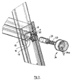
- the spar 2 is locked on the conductor element 1 thereby by a locking bolt that can be moved axially by hand 31, in the cross section of one of the hollow sections trained rungs 22 inserted and from this position can also be deducted.
- Both the locking as well as the unlocked position of the locking bolt 31 is designed as a stable locking device, as is still the case will be show. The details are shown in FIG. 3.
- the substantially tubular locking bolt 31 is in one Guide socket 32 axially and - to a limited extent - also radially movable.
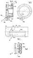
- the guide stub 32 is for this (Fig. 4b) provided with a bearing bore 32a.
- axially parallel Guide grooves 31a (Fig. 5) in the locking bolt 31 penetrated by a transverse pin 32b which, in FIG. 4 indicated, by means of pin bores 32c with the guide socket 32 is pinned after the locking bolt 31 in has been introduced.
- the axial mobility of the The locking bolt 31 is 1 through the length of the guide grooves 31a.
- the entire locking bolt 31 piercing cross pin 32b can also or two short cross pins 32b are used, which are only are driven into the area of the guide groove 31a.
- the guide groove 31a and the cross pin 32b accordingly form an anti-rotation device 31a; 32b of the locking bolt 31 out.
- An end face of the locking bolt 31 on its in the Rungs 22 immersed side is by an example flanged to its hollow cylindrical body 31b End wall 31c at least partially closed; the front wall 31c is somewhat curved (FIG. 5), so that the introduction of the locking bolt 31 in the Hollow profile of a rung 22 is facilitated, and serves as axial fixed bearing for a plunging into the locking bolt 31 Actuator spring 33 (Fig. 3), the locking bolt 31 in Direction of locking the spar 2 loaded; this Position is therefore the normal and without intervention stable position of the lock 3.
- the locking bolt 31 is also fixed with a handle 34 connected, here by means of a connecting pin 34a (Fig. 3).
- the handle 34 is located on another Fixed bearing on the spring 33; for this purpose (Fig. 6) the handle 34 a spring bearing 34b for the as cylindrical compression spring trained spring 33.
- the Spring bearing 34b is designed as an axial cylindrical punch, which is also directed towards the end of the actuating spring 33 has an annular groove 34c into which the locking bolt 31 is axially insertable; one installed in this area Cross bore 34d (Fig. 6) is used to drive the Connecting pin 34a. With a handle 34e of the handle 34 of the locking bolt 31 are moved.
- the guide grooves 31a are on their facing away from the handle 34 End at an acute angle to a short one Angled bend 31d.
- the locking bolt 31 by means of of the handle 34 in its unlocked by the spar 2 Withdrawn position, so it can be rotated a bit, so that the cross pin 32b in the region of the bends 31d device.
- this Under the influence of the actuating spring 33, this is Unlocking position stable because the locking bolt 31st not “automatically” in the axially parallel area of the guide groove 31a, but only with the help of Handle 34 after a short, the action of the spring 33 opposite movement, by which the of the kink 31d formed acute-angled gusset 31e (Fig. 5) can be overcome.
- the conductor element 1 is (Fig. 2, 3) in cross section approximately U-shaped with a web 1a between two angled straps 1b.
- a in the web 1a of the conductor element 1 guide bore 13 no closed for the guide stub 32 has a circular cylindrical contour. Rather, this is on their circumference radially around essentially rectangular holding recesses 14 expanded.
- the - in the embodiment four - form retaining recesses 14 (together with those of included them, the guide holes 13 bordering Surface pieces 15) a counter flange G for one Guide socket 32 leading flange F, the (Fig. 4) from a flange 32d and several (here four) radially adjoining these holding cams 32e consists.
- the holding cams 32e are approximately congruent with the surface the holding recesses 14 in such a way that the guide flange F with its holding cams 32e comfortably through the counter flange G are inserted with its holding recesses 14 can. It then lies approximately on the inside of the web 1a the counter flange G and can be rotated so that its holding cams 32e from the area of the holding recesses 14 guess and rest on the surface pieces 15. In this The position is that of the guide flange F and the counter flange G formed bayonet lock F, G locked.
- the guide flange f cannot go as far through the counter flange G grab because of its axial mobility in this Direction is limited by a collar 32f so that the facing surfaces of the holding cams 32e and the patches 15 are closely adjacent. To this Way, the bayonet lock F, G with relatively winy Axial play can be realized, and the guide flange F remains spaced from the spar 2, so that this at the Rungs 22 released locking bolt 31 freely against the ladder element 1 is movable.
- the guide stub 32 is simple against radial Twist secured.
- a radial eyelet 32g formed with one to the guide stub 32 axially parallel first Pin bore 32h is provided on the guide socket 32 .
- a second pin hole in the web 1a (omitted in the drawing) is arranged that a locking pin in the two pin holes can be driven if the bayonet lock F, G into its locking angular position is rotated. So that can do not release the bayonet lock F, G automatically. Nevertheless the guide socket 32 can be easily changed if necessary or be removed.
Landscapes
- Ladders (AREA)
- Programmable Controllers (AREA)
Applications Claiming Priority (3)
| Application Number | Priority Date | Filing Date | Title |
|---|---|---|---|
| DE29703876U | 1997-03-04 | ||
| DE29703876U DE29703876U1 (de) | 1997-03-04 | 1997-03-04 | Auszugsleiter |
| PCT/EP1998/000844 WO1998039546A1 (de) | 1997-03-04 | 1998-02-14 | Auszugsleiter |
Publications (2)
| Publication Number | Publication Date |
|---|---|
| EP0964976A1 EP0964976A1 (de) | 1999-12-22 |
| EP0964976B1 true EP0964976B1 (de) | 2003-07-30 |
Family
ID=8036908
Family Applications (1)
| Application Number | Title | Priority Date | Filing Date |
|---|---|---|---|
| EP98909464A Expired - Lifetime EP0964976B1 (de) | 1997-03-04 | 1998-02-14 | Auszugsleiter |
Country Status (8)
| Country | Link |
|---|---|
| US (1) | US6220389B1 (ro) |
| EP (1) | EP0964976B1 (ro) |
| CA (1) | CA2280921A1 (ro) |
| DE (2) | DE29703876U1 (ro) |
| HU (1) | HUP0000876A3 (ro) |
| PL (1) | PL188664B1 (ro) |
| RO (1) | RO119155B1 (ro) |
| WO (1) | WO1998039546A1 (ro) |
Families Citing this family (38)
| Publication number | Priority date | Publication date | Assignee | Title |
|---|---|---|---|---|
| US6698550B2 (en) * | 2002-04-04 | 2004-03-02 | Vernon Crain | Adjustable step ladder |
| US6866117B2 (en) | 2002-04-05 | 2005-03-15 | Wing Enterprises, Inc. | Light weight ladder systems and methods |
| US7424933B2 (en) * | 2002-05-28 | 2008-09-16 | Norman Miller | Ladder assemblies |
| US6622822B1 (en) | 2002-08-01 | 2003-09-23 | Volvo Trucks North America, Inc. | Bunk ladder |
| WO2004044365A2 (en) | 2002-11-11 | 2004-05-27 | Wing Enterprises | Combination ladders, ladder components and methods of manufacturing same |
| US20050269159A1 (en) * | 2004-06-07 | 2005-12-08 | Lin Cho S | Telescopic stepladder |
| US20060076190A1 (en) * | 2004-10-08 | 2006-04-13 | Vernon Crain | Step ladder |
| US20060213721A1 (en) * | 2005-03-25 | 2006-09-28 | Mario Uttaro | Multiple laddering system - the ultimate foldaway system |
| USD541430S1 (en) * | 2005-10-19 | 2007-04-24 | Anthony Restaino | Unfolding stepladder |
| USD541433S1 (en) | 2005-12-14 | 2007-04-24 | Robert Wise | Top tray and a flip down tray combination for a ladder |
| USD553757S1 (en) | 2006-02-11 | 2007-10-23 | Wing Enterprises, Inc. | Ladder hinge pair |
| US8490747B2 (en) * | 2006-06-30 | 2013-07-23 | Werner Co. | Telescoping project tray |
| CN103590743B (zh) * | 2008-03-07 | 2017-01-11 | 伟英企业有限公司 | 梯子 |
| AU2013200666B2 (en) * | 2008-03-07 | 2015-07-02 | Wing Enterprises, Inc. | Ladders, ladder components and related methods |
| US8464833B2 (en) * | 2010-10-05 | 2013-06-18 | Ge Lee | Adjustable hang ladder with fall arresting and cushioning arrangement |
| CA3057031C (en) | 2011-02-22 | 2022-01-11 | Wing Enterprises, Incorporated | Ladders, ladder components and related methods |
| EP2893116B1 (en) * | 2012-09-05 | 2017-07-19 | Branach Technology Pty Ltd | Improved releasable coupling for ladder section and the like |
| US9404305B1 (en) * | 2014-03-26 | 2016-08-02 | Mark S. Messick | Portable and adaptable platform |
| US9670726B2 (en) * | 2014-05-15 | 2017-06-06 | Kang-Shuo Yeh | Multi-purpose ladder with improved rungs |
| US10487576B2 (en) | 2016-03-04 | 2019-11-26 | Wing Enterprises, Incorporated | Adjustment mechanisms, ladders incorporating same and related methods |
| US10900282B2 (en) * | 2016-12-21 | 2021-01-26 | James B. Ford | Safety ladder |
| CN107178303A (zh) * | 2017-03-03 | 2017-09-19 | 厦门新技术集成有限公司 | 一种可变换直梯使用的人字梯 |
| US10557227B2 (en) * | 2017-04-14 | 2020-02-11 | Whitmor, Inc. | Drying rack |
| US20180363371A1 (en) * | 2017-06-20 | 2018-12-20 | Thomas Huckabay | Adjustable ladder device and method |
| USD833643S1 (en) | 2017-07-07 | 2018-11-13 | Tricam Industries, Inc. | Integrated ladder tray hook |
| US11280133B2 (en) * | 2018-01-30 | 2022-03-22 | Werner Co. | 7000 series aluminum alloy ladder, multipurpose ladder and method |
| US11851949B2 (en) * | 2018-01-30 | 2023-12-26 | Werner Co. | Multipurpose ladder and method |
| CA3291256A1 (en) * | 2018-06-08 | 2026-02-10 | Little Giant Ladder Systems, Llc | Combination ladders, ladder components and related methods |
| USD935054S1 (en) | 2018-10-19 | 2021-11-02 | Little Giant Ladder Systems, Llc | Ladder |
| USD943772S1 (en) | 2018-10-19 | 2022-02-15 | Little Giant Ladder Systems, Llc | Flip-up ladder |
| CA3123005A1 (en) | 2018-12-13 | 2020-06-18 | Murphy Ladder Llc | Foldable and collapsible ladder |
| WO2020154675A1 (en) | 2019-01-25 | 2020-07-30 | Wing Enterprises, Incorporated | Foot for ladders, ladders incorporating same and related methods |
| USD911555S1 (en) | 2019-02-08 | 2021-02-23 | Little Giant Ladder Systems, Llc | Top cap for a ladder |
| USD908924S1 (en) * | 2019-05-14 | 2021-01-26 | Werner Co. | Multipurpose ladder |
| USD935055S1 (en) | 2019-08-07 | 2021-11-02 | Tricam Industries, Inc. | Hinge for a multi-position ladder |
| USD966556S1 (en) * | 2019-12-13 | 2022-10-11 | Murphy Ladder Llc | Ladder |
| USD949438S1 (en) * | 2020-01-19 | 2022-04-19 | Aukey Technology Co., Ltd | Ladder |
| US12601221B1 (en) * | 2025-09-05 | 2026-04-14 | Miaoren CHEN | Ladder that facilitates the contraction of handrails |
Family Cites Families (12)
| Publication number | Priority date | Publication date | Assignee | Title |
|---|---|---|---|---|
| US3858684A (en) * | 1973-06-27 | 1975-01-07 | Harford E Goings | Telescoping ladder |
| US4182431A (en) * | 1978-03-13 | 1980-01-08 | Little Giant Industries Inc. | Combination extension and step ladder rungs therefor |
| FR2478550A1 (fr) * | 1980-03-21 | 1981-09-25 | Mecanismes Comp Ind De | Dispositif de montage d'une bras de support et d'articulation de pare-soleil de vehicule |
| US4376470A (en) * | 1980-11-06 | 1983-03-15 | Little Giant Industries, Inc. | Fiberglass ladder |
| US4371055A (en) * | 1980-11-07 | 1983-02-01 | Little Giant Industries, Inc. | Method of manufacturing a fiberglass ladder |
| US4606432A (en) * | 1984-10-29 | 1986-08-19 | Belt Ned W | Adjustable ladder leg |
| US4951780A (en) * | 1988-08-08 | 1990-08-28 | Kim Myung H | Combination ladder and height adjustable scaffold |
| DE8814195U1 (de) * | 1988-11-12 | 1989-01-26 | Krause-Werk Gmbh & Co Kg, 6320 Alsfeld | Gelenkleiter |
| US4854420A (en) * | 1988-11-15 | 1989-08-08 | Juang Yuan C | Securing means for a double step ladder |
| BE1004040A6 (fr) * | 1989-06-16 | 1992-09-15 | Show Min Liaw | Echelle extensible a usages multiples. |
| US5062499A (en) * | 1990-10-10 | 1991-11-05 | Tu Ching Chuan | Side rails fastening mechanism for telescopic aluminum step ladders |
| KR940020881U (ko) | 1993-02-01 | 1994-09-17 | 유회관 | 사다리의 높낮이 조절장치 |
-
1997
- 1997-03-04 DE DE29703876U patent/DE29703876U1/de not_active Expired - Lifetime
-
1998
- 1998-02-14 DE DE59809157T patent/DE59809157D1/de not_active Expired - Lifetime
- 1998-02-14 US US09/355,677 patent/US6220389B1/en not_active Expired - Fee Related
- 1998-02-14 RO RO99-00945A patent/RO119155B1/ro unknown
- 1998-02-14 HU HU0000876A patent/HUP0000876A3/hu unknown
- 1998-02-14 CA CA002280921A patent/CA2280921A1/en not_active Abandoned
- 1998-02-14 WO PCT/EP1998/000844 patent/WO1998039546A1/de not_active Ceased
- 1998-02-14 EP EP98909464A patent/EP0964976B1/de not_active Expired - Lifetime
- 1998-02-14 PL PL98334064A patent/PL188664B1/pl unknown
Also Published As
| Publication number | Publication date |
|---|---|
| PL334064A1 (en) | 2000-01-31 |
| CA2280921A1 (en) | 1998-09-11 |
| WO1998039546A1 (de) | 1998-09-11 |
| EP0964976A1 (de) | 1999-12-22 |
| DE59809157D1 (de) | 2003-09-04 |
| RO119155B1 (ro) | 2004-04-30 |
| HUP0000876A3 (en) | 2003-12-29 |
| US6220389B1 (en) | 2001-04-24 |
| PL188664B1 (pl) | 2005-03-31 |
| HUP0000876A2 (hu) | 2000-08-28 |
| DE29703876U1 (de) | 1998-07-02 |
Similar Documents
| Publication | Publication Date | Title |
|---|---|---|
| EP0964976B1 (de) | Auszugsleiter | |
| DE3235857C2 (ro) | ||
| DE19833857B4 (de) | Kinderwagen | |
| DE2902738C2 (de) | Abnehmbare Schulterstütze für Pistolen | |
| DE602004005310T2 (de) | Bohrgestänge | |
| DE2520237C2 (de) | Vorrichtung zur lösbaren Verbindung zweier rohrförmiger Bohrlochelemente | |
| EP0645296B1 (de) | Handwagen nach Art eines Leiterwagens | |
| DE69815119T2 (de) | Bremseinrichtung | |
| DE2753736A1 (de) | Vorrichtung zur verbindung zweier teile, insbesondere beim moebelbau | |
| DE60011358T2 (de) | Sicherheitsvorrichtung | |
| DE29911334U1 (de) | Zusammenklappvorrichtung für Golfwagen | |
| EP1338723A2 (de) | Vorrichtung zur Montage eines temporär vorhandenen Geländerholms eines Gerüstes | |
| EP1883078A1 (de) | Vorrichtung zur Handhabung von Kleinbauteilen | |
| EP1138849A2 (de) | Rohrelement | |
| DE29619438U1 (de) | Befestigungsvorrichtung für eine Gerätehandhabe für Gartengeräte | |
| DE102004055394A1 (de) | Baugerüst, Geländereinrichtung eines Baugerüstes sowie Verbindungsanordnung für eine Geländereinrichtung eines Baugerüstes | |
| DE2435250A1 (de) | Ineinandersteckbare bauteile mit sicherheitsverriegelung, insbesondere rohrfoermige bauteile fuer arbeitsgerueste | |
| DE3105216C2 (ro) | ||
| DE2656872C2 (de) | Ständer mit verstellbarem Schrägarm | |
| DE10034592C1 (de) | Vorrichtung zur Höhenverstellung von teleskopartig ineinandergreifenden Rohren | |
| EP1668218B1 (de) | Leiter mit sicherheitseinrichtung | |
| DE2228045A1 (de) | Ausziehbare bockleiter | |
| DE2217258C3 (de) | Gelenkbeschlag für klappbare Leitern | |
| DE2321346A1 (de) | Gelenkbeschlag fuer klappbare leitern | |
| EP0317661A1 (de) | Teleskopgabelbaum |
Legal Events
| Date | Code | Title | Description |
|---|---|---|---|
| PUAI | Public reference made under article 153(3) epc to a published international application that has entered the european phase |
Free format text: ORIGINAL CODE: 0009012 |
|
| 17P | Request for examination filed |
Effective date: 19990315 |
|
| AK | Designated contracting states |
Kind code of ref document: A1 Designated state(s): DE FR GB IT |
|
| GRAH | Despatch of communication of intention to grant a patent |
Free format text: ORIGINAL CODE: EPIDOS IGRA |
|
| GRAH | Despatch of communication of intention to grant a patent |
Free format text: ORIGINAL CODE: EPIDOS IGRA |
|
| GRAA | (expected) grant |
Free format text: ORIGINAL CODE: 0009210 |
|
| AK | Designated contracting states |
Designated state(s): DE FR GB IT |
|
| REG | Reference to a national code |
Ref country code: GB Ref legal event code: FG4D Free format text: NOT ENGLISH |
|
| GBT | Gb: translation of ep patent filed (gb section 77(6)(a)/1977) |
Effective date: 20030806 |
|
| REF | Corresponds to: |
Ref document number: 59809157 Country of ref document: DE Date of ref document: 20030904 Kind code of ref document: P |
|
| ET | Fr: translation filed | ||
| PLBE | No opposition filed within time limit |
Free format text: ORIGINAL CODE: 0009261 |
|
| STAA | Information on the status of an ep patent application or granted ep patent |
Free format text: STATUS: NO OPPOSITION FILED WITHIN TIME LIMIT |
|
| 26N | No opposition filed |
Effective date: 20040504 |
|
| PGFP | Annual fee paid to national office [announced via postgrant information from national office to epo] |
Ref country code: IT Payment date: 20100223 Year of fee payment: 13 |
|
| PG25 | Lapsed in a contracting state [announced via postgrant information from national office to epo] |
Ref country code: IT Free format text: LAPSE BECAUSE OF NON-PAYMENT OF DUE FEES Effective date: 20110214 |
|
| PGFP | Annual fee paid to national office [announced via postgrant information from national office to epo] |
Ref country code: GB Payment date: 20120221 Year of fee payment: 15 |
|
| GBPC | Gb: european patent ceased through non-payment of renewal fee |
Effective date: 20130214 |
|
| PG25 | Lapsed in a contracting state [announced via postgrant information from national office to epo] |
Ref country code: GB Free format text: LAPSE BECAUSE OF NON-PAYMENT OF DUE FEES Effective date: 20130214 |
|
| REG | Reference to a national code |
Ref country code: FR Ref legal event code: PLFP Year of fee payment: 18 |
|
| PGFP | Annual fee paid to national office [announced via postgrant information from national office to epo] |
Ref country code: FR Payment date: 20150219 Year of fee payment: 18 |
|
| PGFP | Annual fee paid to national office [announced via postgrant information from national office to epo] |
Ref country code: DE Payment date: 20160225 Year of fee payment: 19 |
|
| REG | Reference to a national code |
Ref country code: FR Ref legal event code: ST Effective date: 20161028 |
|
| PG25 | Lapsed in a contracting state [announced via postgrant information from national office to epo] |
Ref country code: FR Free format text: LAPSE BECAUSE OF NON-PAYMENT OF DUE FEES Effective date: 20160229 |
|
| REG | Reference to a national code |
Ref country code: DE Ref legal event code: R119 Ref document number: 59809157 Country of ref document: DE |
|
| PG25 | Lapsed in a contracting state [announced via postgrant information from national office to epo] |
Ref country code: DE Free format text: LAPSE BECAUSE OF NON-PAYMENT OF DUE FEES Effective date: 20170901 |