EP0964490A2 - Zündkerze - Google Patents
Zündkerze Download PDFInfo
- Publication number
- EP0964490A2 EP0964490A2 EP99304555A EP99304555A EP0964490A2 EP 0964490 A2 EP0964490 A2 EP 0964490A2 EP 99304555 A EP99304555 A EP 99304555A EP 99304555 A EP99304555 A EP 99304555A EP 0964490 A2 EP0964490 A2 EP 0964490A2
- Authority
- EP
- European Patent Office
- Prior art keywords
- semi
- face
- insulator
- ground electrode
- spark plug
- Prior art date
- Legal status (The legal status is an assumption and is not a legal conclusion. Google has not performed a legal analysis and makes no representation as to the accuracy of the status listed.)
- Granted
Links
Images







Classifications
-
- H—ELECTRICITY
- H01—ELECTRIC ELEMENTS
- H01T—SPARK GAPS; OVERVOLTAGE ARRESTERS USING SPARK GAPS; SPARKING PLUGS; CORONA DEVICES; GENERATING IONS TO BE INTRODUCED INTO NON-ENCLOSED GASES
- H01T13/00—Sparking plugs
- H01T13/46—Sparking plugs having two or more spark gaps
- H01T13/467—Sparking plugs having two or more spark gaps in parallel connection
-
- H—ELECTRICITY
- H01—ELECTRIC ELEMENTS
- H01T—SPARK GAPS; OVERVOLTAGE ARRESTERS USING SPARK GAPS; SPARKING PLUGS; CORONA DEVICES; GENERATING IONS TO BE INTRODUCED INTO NON-ENCLOSED GASES
- H01T13/00—Sparking plugs
- H01T13/20—Sparking plugs characterised by features of the electrodes or insulation
- H01T13/32—Sparking plugs characterised by features of the electrodes or insulation characterised by features of the earthed electrode
Definitions
- the present invention relates to a spark plug used for ignition in an internal combustion engine.
- a conventional type spark plug is provided with a central electrode and a parallel ground electrode.
- the central electrode is protruded downward from the lower end face of insulator.
- the parallel ground electrode is arranged opposite to the central electrode and one end of which is bonded to main metal shell for igniting fuel mixed gas by spark discharge in an air gap between the central electrode and the parallel ground electrode.
- a spark plug provided with auxiliary ground electrodes opposite to the side face of a central electrode in addition to a parallel ground electrode opposite to the end face of the central electrode is proposed in Unexamined Japanese Patent Publication (kokai) No. Hei. 5-326107, U.S. Patent No. 5,581,145 and EP 0 774 812A.
- These auxiliary ground electrodes are not provided to jump sparks in a gap between the auxiliary ground electrode and the central electrode.
- these auxiliary ground electrodes are provided to improve the distribution of electric fields between the parallel ground electrode and the central electrode by the existence of the auxiliary ground electrodes. Accordingly, ignitability is enhanced by jumpinga spark in the gap between the parallel ground electrode and the central electrode at lower discharge voltage. Therefore, in the structure of these spark plugs, the edge of the end face of the auxiliary ground electrode is not necessarily positioned in the vicinity of the lower end face of the insulator.
- firing sparks and derived expressions used herein may refer to causing a spark to jump a gap, a spark discharge to occur, and so on.
- a spark plug according to the present invention comprises an insulator, a central electrode, a main metal shell, a parallel ground electrode and at least one semi-surface ground electrode.
- the insulator has a central through hole.
- the central electrode is held in said central through hole and protruded from the lower end face of said insulator downward.
- the main metal shell for holding said insulator.
- the parallel ground electrode having one end which is bonded to the main metal shell and the other end which is arranged so that the other end is opposite to the end face of said central electrode for holding said insulator and a parallel ground electrode arranged.
- Amain air gap (A) is formed by said parallel ground electrode and the end face of said central electrode.
- the at least one semi-surface ground electrode has one end which is bonded to said main metal shell and the other end which is arranged so that the other end is opposite to the side face of said central electrode or the side face of said insulator.
- a semi-surface gap (B) is formed between the end face of the other end of said semi-surface ground electrode and the side face of said central electrode opposite to the end face.
- a gap (C) between a semi-surface ground electrode and the insulator hereinafter, referred to "a semi-surface air gap (C))is formed between the end face of said semi-surface ground electrode and the side face of said insulator opposite to the end face.
- difference in a level E between the height of the lower end face of said insulator and the height of the upper edge of the end face of said semi-surface ground electrode is equal to or smaller than +0.7mm where '+' means a direction in which the upper edge of the end face of the semi-surface ground electrode separates downward from the lower end face of the insulator.
- the distance B of said semi-surface gap (B) is longer than the distance A of said main air gap (A).
- a first extended line acquired by extending a line showing said lower end face of said insulator outward a second extended line acquired by extending a line showing the side face in the vicinity of the semi-surface gap (B) of said insulator in the direction of said lower end face and a third extended line acquired by extending a line showing the end face of said semi-surface ground electrode downward are drawn in case the end face of said semi-surface ground electrode and said insulator are cut along the central axis of said insulator, distance that is a distance C of a semi-surface air gap (C) between the intersection of said first and second extended lines and the intersection of said first and third extended lines is shorter than the distance A of said main air gap (A).
- a spark plug according to the present invention comprises an insulator, a central electrode, a main metal shell, and a main ground electrode, also known as a parallel ground electrode.
- the insulator is provided with a central through hole.
- the central electrode is held in the above central through hole and protruded downward from the lower end face of the insulator.
- the main metal shell holds the insulator.
- the parallel ground electrode has one end which is bonded to the main metal shell and the other end which is arranged opposite to the end face of the central electrode.
- a main air gap (A) is formed by the parallel ground electrode and the end face of the central electrode.
- the spark plug is further provided with a single or plural semi-surface ground electrodes one end of which is bonded to the above main metal shell and the other end of which is arranged opposite to the side face of the central electrode or the side face of the insulator.
- a semi-surface gap (B) is formed between the end face of the other end of the semi-surface ground electrode and the side face of the central electrode opposite to the end face.
- a semi-surface air gap (C) is formed between the end face of the semi-surface ground electrode and the side face of the insulator opposite to the end face.
- a difference in a level E between the height of the lower end face of the insulator and the height of the upper edge of the end face of the semi-surface ground electrode is equal to or smaller than +0.7 mm, ('+' means a direction in which the upper edge of the end face of the semi-surface ground electrode separates downward from the lower end face of the insulator).
- the distance B of the semi-surface gap (B) is longer than the distance A of the main air gap (A).
- a first extended line acquired by extending a line showing the lower end face of the insulator outward a second extended line acquired by extending a line showing the side face in the vicinity of the semi-surface gap (B) of the insulator in the direction of the above lower end face and a third extended line acquired by extending a line showing the end face of the semi-surface ground electrode downward are drawn respectively in case the end face of the semi-surface ground electrode and the insulator are cut along the central axis of the insulator, distance (hereinafter called the distance C of a semi-surface air gap (C) from the intersection of the first and second extended lines to the intersection of the first and third extended lines is shorter than the distance A of the main air gap (A).
- the spark plug is shown so that the end face of the central electrode is located down.
- the distance A of the main air gap (A) is shorter (A ⁇ B) than the distance B of the semi-surface gap (B) by structured above, spark discharge is generated in the main air gap (A) between the central electrode and the parallel ground electrode at normal time at which no carbon fouling state is caused.
- the distance C of the semi-surface air gap (C) is shorter (C ⁇ A) than the distance A of the main air gap (A) and difference in a level E between the height of the lower end face of the insulator and the height of the upper edge of the end face of the semi-surface ground electrode is equal to or smaller than +0.7 mm.
- spark discharge is generated between the edge of the semi-surface ground electrode and the side face of the central electrode via the surface of the lower end face of the insulator (hereinafter called semi-surface discharge).
- semi-surface discharge After spark of semi-surface discharge fly in the semi-surface air gap (C), it runs along the surface of the insulator.
- carbon accumulated on the lower end face of the insulator is burned off.
- the surface of the insulator is restored to a clean state. Insulation on the surface of the insulator is again recovered.
- a carbon fouling is dissolved and spark discharge is generated in not the semi-surface gap (B) but the main air gap (A).
- the present invention produces the following effect.
- spark discharge is generated in the main air gap (A) between the central electrode and the parallel ground electrode in most time. Only at the time of a carbon fouling state in which the surface of the insulator is fouled by carbon, semi-surface discharge is generated the semi-surface gap (B) with the semi-surface ground electrode and fuel mixture in a combustion chamber is ignited. As fuel mixture is ignited by spark discharge in the main air gap (A) in most time, the spark plug is excellent in ignitability. As semi-surface discharge is provided with self-cleaning action in which carbon accumulated on the surface of the insulator is burned off, the spark plug is extremely strong in a carbon fouling. Further, as the frequency in which semi-surface discharge is generated is low and the discharge time is extremely short, the action of channeling by sparks is weakened and channeling is hardly caused. Therefore, the life of this spark plug is sufficiently long.
- the distance A of the main air gap (A), the distance B of the semi-surface gap (B) and the distance C of the semi-surface air gap (C) can be in the relation ship of "A ⁇ (0.8(B - C)+C)"mm.
- the spark plug is formed as described above, at normal time at which the spark plug is not in carbon fouling state, the rate of flying sparks in the main air gap (A) is 50% or more. Therefore, at normal time, sparks fly in the main air gap (A) and the spark plug is advantageous in consideration of ignitability and channeling.
- the distance B of the semi-surface gap (B) can be equal to or shorter than 2.2mm
- the distance C of the semi-surface air gap (C) is equal or longer than 0.4mm and is equal or shorter than (A - 0.1) mm (A: the distance of the main air gap (A)).
- difference in a level E between the height of the lower end face of the insulator and the height of the upper edge of the end face of the semi-surface ground electrode can be preferably equal to or smaller than +0.5 mm ('+' means a direction in which the upper edge of the end face of the semi-surface ground electrode separates downward from the lower end face of the insulator).
- spark cleaning action of the surface of the insulator by the sparks of semi-surface discharge can be effectively maintained. If difference in a level E between the height of the lower end face of the insulator and the height of the edge of the upper end face of the semi-surface ground electrode is larger than +0.5 mm, the sparks of semi-surface discharge reach the lower end face of the insulator and the effect of spark cleaning action of the surface of the insulator may be deteriorated.
- discharge voltage may be increased in a spark plug without the parallel ground electrode.
- the parallel ground electrode in the spark plug also provided with the parallel ground electrode according to the present invention no discharge voltage is increased.
- the cross section of the semi-surface ground electrode is 3 mm 2 or smaller.
- the generation of a bridge at the time of a start at low temperature can be inhibited by forming as described above.
- the above difference in a level E can be equal to or smaller than -0.7 mm.
- Spark cleaning action on the surface of the insulator by sparks of semi-surface discharge can be further effectively maintained by forming as described above.
- quantity H in which the central electrode is protruded from the lower end face of the insulator can be equal to or larger than 1.0 mm and is equal to or smaller than 4.0 mm.
- the waste of the central electrode due to semi-surface discharge can be reduced by forming as described above. Difference between ignitability by spark discharge in the main air gap (A) with a parallel ground electrode and the ignitability of a semi-surface ground electrode by semi-surface discharge can be reduced and the variation of the torque of an internal combustion engine due to the change of ignitability according to the change of a discharge electrode can be inhibited as much as possible.
- the quantity H in which the central electrode is protruded is smaller than 1.0 mm, the waste of the side face of the central electrode increases.
- H is equal to or smaller than 2.0 mm.
- the diameter at the end of the central electrode can be reduced, compared with the diameter at the base protruded from the lower end face of the insulator, the diameter D1 at the end of the central electrode is equal or longer than 0.4mm and is equal to or shorter than 1.6mm, and the diameter D2 at the base of the central electrode protruded from the lower end face of the insulator is equal to or longer than (D1 + 0.3 mm).
- the diameter D2 at the base of the central electrode can be equal to or longer than 2.0mm.
- the end of the central electrode can be further effectively prevented from being overheated by forming so that the diameter at the base of the central electrode is long as described above and the waste of the central electrode in the case of discharge in the semi-surface gap (B) can be inhibited.
- concentration of electric fields is reduced by extending the diameter D2 at the base of the central electrode, the rate of the generation of sparks in the semi-surface gap (B) at normal time can be reduced.
- nickel is used as a main component and it is further desirable that an alloy provided with the good conductivity of heat in which nickel content is 85 percentage by weight or more is used.
- Heat is further reduced by increasing a nickel content as described above and the waste of the central electrode in the case of discharge in the semi-surface gap (B) can be further inhibited.
- the main air gap (A) is widened in case the semi-surface gap (B) is fixed, discharge in the semi-surface gap (B) is increased.
- the wider the main air gap is made the more desirable it is, however, it is considered that discharge in the semi-surface gap is also related to the width of the main air gap (A).
- the diameter D2 at the base of the central electrode is set to approximately the double of the distance A of the main air gap (A) or longer.
- the end of the central electrode can be made of noble metal the melting point of which is 1600°C or more such as a platinum alloy and an iridium alloy.
- the wear resistance to spark discharge of the central electrode is enhanced and the life of the spark plug is extended.
- the material the particularly above nickel content of which is 85 percentage by weight or more of the central electrode is used.
- the waste by oxidation of which is much particularly at high temperature can be lowered, it is very advantageous to the waste of noble metal.
- the semi-surface ground electrode can be a straight pole and the side of the semi-surface ground electrode is bonded to the lower end face of the main metal shell.
- the semi-surface ground electrode is located in the vicinity of the lower end face of insulator, the following problem may be caused if the dimension in which the insulator is protruded from the lower end face of the main metal shell is small. That is, the semi-surface ground electrode is bonded to the lower end face of the main metal shell by welding and others, however, the vicinity of the bonded part is required to be bent in the approximately shape of a letter L on the side of the central electrode. Therefore, the curvature of the bent part is required to be reduced and manufacturing problems such as breakage and a crack may be caused. Therefore, such problems can be solved by forming according to the present invention.
- Fig. 1 is a partial sectional view showing a spark plug equivalent to the first embodiment.
- Insulator 1 made of alumina and others is provided with corrugations 1A to extend surface distance in the upper part and a leg portion 1B exposed to the combustion chamber of an internal combustion engine in the lower part and a central through hole 1C in the axial center.
- a central electrode 2 made of a nickel alloy such as Inconel is held in a state that the central electrode 2 is protruded downward from the lower surface of the insulator 1.
- the central electrode 2 is electrically connected to an upper terminal nut 4 via a ceramic resistor 3 provided inside the central through hole 1C.
- the above insulator 1 is connected to the terminal nut 4 and high voltage is applied to the terminal nut.
- the above insulator 1 is supported by main metal shell 5 with the insulator surrounded by the main metal shell.
- the main metal shell 5 is made of low-carbon steel and is composed of a hexagonal part 5A for engaging with a spark plug wrench and a thread part 5B.
- the main metal shell 5 is staked to the insulator 1 by its staking part 5C and the main metal shell 5 and the insulator 1 are integrated.
- a disc packing member 6 and sealing members 7 and 8 in the shape of wire are inserted between the main metal shell 5 and the insulator 1 and talc powder 9 is filled between the sealing members 7 and 8.
- a gasket 10 is fitted to the upper end of the thread part 5B.
- a parallel ground electrode 11 made of a nickel alloy is bonded to the lower end of the main metal shell 5 by welding.
- the parallel ground electrode 11 is axially opposed to the end face of the central electrode 2, and the central electrode 2 and the parallel ground electrode 11 form a main air gap (A).
- the spark plug according to this embodiment is provided with two semi-surface ground electrodes 12 in addition to the parallel ground electrode 11.
- the semi-surface ground electrode 12 is made of a nickel alloy, one end is bonded to the lower end of the main metal shell 5 by welding and the end face 12C of the other end is opposed to the side face 2A of the central electrode 2 or the side face 1E of the leg portion 1B.
- the two semi-surface ground electrodes 12 are respectively arranged in a position off by 90° from the parallel ground electrode 11 and each semi-surface ground electrode 12 is arranged in a position off by 180° from each other.
- each semi-surface ground electrode 12 and the side face 2A of the central electrode 2 form a semi-surface gap (B), and the end face 12C of each semi-surface ground electrode 12 and the side face 1E of the leg portion 1B form a semi-surface air gap (C).
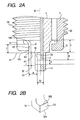
- Fig. 2A is a partial sectional view showing the enlarged vicinity of the central electrode 2, the parallel ground electrode 11 and the semi-surface ground electrode 12 of the spark plug.
- Fig. 2B is an explanatory drawing showing the enlarged semi-surface ground electrode 12.
- A The distance of the main air gap (A) between the end face of the central electrode 2 and the parallel ground electrode 11 is A.
- the distance of the semi-surface gap (B) between the side face 2A of the central electrode 2 and the end face 12C of the semi-surface ground electrode 12 is B.
- a first extended line 31 is acquired by extending a line showing the lower end face 1D of the insulator 1 outward.
- a second extended line 32 is acquired by extending a line showing the side face 1E in the vicinity of the semi-surface gap (B) of the insulator 1 in the direction of the lower end face 1D.
- a third extended line 33 is acquired by extending a line showing the end face 12C of the semi-surface ground electrode 12 downward.
- discharge can be made via the main air gap (A) between the insulator and the parallel ground electrode 11.
- discharge can be made via the semi-surface gap (B) between the insulator and the semi-surface ground electrode 12.
- E The difference in a level between the lower end face 1D of the insulator 1 and the upper edge 12B of the end face 12C of the semi-surface ground electrode 12 is E.
- the quantity in which the insulator 1 is protruded from the lower end face 5D of the main metal shell 5 shall is F.
- the quantity in which the central electrode 2 is protruded from the lower end face 1D of the insulator 1 is H.
- the quantity F in which the insulator 1 is protruded is set to 3.0 mm.
- the diameter D2 of the central electrode 2 is set to 2.0 mm.
- the semi-surface ground electrode having the width of 2.2 mm and the thickness of 1.3 mm is used.
- the parallel ground electrode 11 having the width of 1.5 mm and the thickness of 2.8 mm is used.
- the parallel ground electrode 11 provided with a copper core may be also used to lower the temperature of the end and prevent a spark from being wasted.
- the upper edge 12B and the lower edge 12A respectively shown in Fig. 2B of the semi-surface ground electrode 12 are located higher than the lower end face 1D of the insulator 1 as shown in Fig. 2 (a).
- the upper edge 12B of the semi-surface ground electrode 12 is located higher than the lower end face 1D of the insulator 1 as shown in Fig. 3.
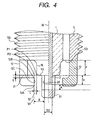
- the upper edge 12B of the semi-surface ground electrode 12 is located lower than the lower end face 1D of the insulator 1 as shown in Fig. 4 respectively depending upon the height of the semi-surface ground electrode 12.
- either of the upper edge 12B and the lower edge 12A of the end face 12C of the semi-surface ground electrode 12 is located at the height of the vicinity of the lower end face 1D of the insulator 1. That is, it is desirable that the difference in a level E is small.
- the reason is that sparks which fly from the upper edge 12B and the lower edge 12A are brought close to the lower end face 1D of the insulator 1 and self-cleaning action in which carbon which accumulates on the surface of the insulator 1 is burned is enhanced because semi-surface discharge is made at an acute angle. Accordingly, it is considered that sparks fly from the upper edge 12B and the lower edge 12A of the semi-surface ground electrode 12 in which electric fields concentrate. (Grounds thatB is equal to or shorter than 2.2 mm)
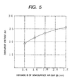
- Fig. 5 is a graph showing relationship between the distance B of the semi-surface gap (B) and discharge voltage.
- a test from idling to racing in which an engine was operated and racing was made by opening a throttle wide from the state of idling to observe discharge voltage was made.
- the parallel ground electrode 11 of which is cut in a part welded to the main metal shell 5 is used.
- a straight 4-cylinder engine provided with the displacement of 1.6 1. is used.
- the distance B of the semi-surface gap (B) exceeds 2.2 mm, discharge voltage exceeds 25 kV and so-called flashover in which sparks fly from the central electrode 2 to the vicinity of the base of the leg portion 1B of the insulator 1 of the main metal shell 5 before discharge is generated between the semi-surface ground electrode 12 and the central electrode 2 may be caused. Therefore, it is required that the distance B of the semi-surface gap (B) is 2.2 mm or less. (Grounds that A ⁇ (0.8(B-C)+C)mm and 0.4 ⁇ C ⁇ (A-0.1)mm)
- Fig. 6 is a graph showing the rate of flying sparks of 50% in which points where the rate of flying sparks in the main air gap (A) and the semi-surface air gap (C) is respectively 50% are plotted.
- the rate of flying sparks is evaluated by an armchair test in which the direction of flying sparks is observed by installing the spark plug in a chamber provided with a window from which the main air gap (A) and the semi-surface gap (B) can be observed.
- a sample the insulation resistance value of which is lowered up to 5 to 10 M ⁇ using a general-purpose engine and others beforehand is prepared.
- a straight line 101 shows the rate of flying sparks of 50% measured at normal time when the spark plug is not in a carbon fouling state in case the part of the lower end face 1D of the insulator 1 in the semi-surface gap (B).
- the difference (B - C) between the distance B of the semi-surface gap (B) and the distance C of the semi-surface air gap (C) is 1.0 mm
- a straight line 101' similarly shows the rate of flying sparks of 50% in case the above difference (B - C) is 1.2 mm
- a straight line 101" similarly shows the rate of flying sparks of 50% in case the difference (B - C) is 0.8 mm.
- an area AA on the left side of the straight line 101 is an area in which sparks also fly in the semi-surface air gap (C) at normal time and areas BB and CC on the right side of the straight line 101 are areas in which sparks fly in the main air gap (A) at normal time.
- areas AA and BB-on the left side of the straight line 102 are areas in which sparks fly in the semi-surface air gap (C) at carbon fouling time and an area CC on the right side of the straight line 102 is an area in which sparks also fly in the main air gap (A) at carbon fouling time. Therefore, an area in which sparks fly in the main air gap (A) at normal time and sparks fly in the semi-surface air gap (C) at carbon fouling time is the area BB between the two straight lines 101 and 102.
- the pre-delivery fouling means fouling in which the temperature of a spark plug does not rise and the spark plug becomes a carbon fouling state because a new car is driven by extremely short distance many times from the assembly factory of cars to a dealer and the insulation resistance of the spark plug is deteriorated.
- a method of locating a car in a low-temperature test room of -10°C as defined in a low-load compatibility test in JIS D 1606, operating it by 10 cycles having a predetermined operation pattern including inching a few times at low speed as one cycle and measuring the insulation resistance value of a spark plug at the middle and the end of each cycle is taken.
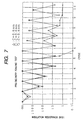
- Fig. 7 shows an example of a pre-delivery fouling test of spark plugs different in the distance C of the semi-surface air gap (C).
- ⁇ shows the insulation resistance measured value of a double-pole semi-surface spark plug when C is 0.4 mm
- ⁇ shows the above value when C is 0.6 mm
- ⁇ shows the above value when C is 0.8 mm.
- a straight 6-cylinder engine provided with the displacement of 2.5 l. is used.
- C is 0.4 mm, a carbon bridge is caused in six cycles, discharge is disabled and an engine stall is caused.
- Fig. 8 shows the approximate probability of failure in which the above pre-delivery fouling test is made some times, a carbon bridge is caused and an engine stall is caused and the x-axis shows the distance C of the semi-surface air gap (C).
- the distance C of the semi-surface air gap (C) is required to meet the following expression (3)(unit: mm). 0.4 ⁇ C (mm)
- the distance C of the semi-surface air gap (C) meets at least the following expression (4).
- 0.4 ⁇ C ⁇ A - 0.1 rounds that E ⁇ +0.7 mm, desirably E ⁇ +0.5 mm
- the difference in a level E between the lower end face 1D of the insulator 1 and the upper edge 12B of the semi-surface ground electrode 12 is +0.7 mm or less and it is preferable that it is +0.5 mm or less.
- '+' means a direction in which the upper edge 12B of the end face 12C of the semi-surface ground electrode 12 separates from the lower end face 1D of the insulator 1 downward.
- the difference in a level E has only to be +0.7 mm or less (E ⁇ +0.7) as clear from the above table 1 and it is desirable that the difference in a level E is +0.5 mm or less (E ⁇ +0.5).
- the dimension of E it is not preferable that the dimension of E is too small. If the dimension of E is made too small, the distance of the semi-surface discharge becomes long, the discharge voltage bocomes high, and sparks are hard to fly. Accordingly, it is difficult to eliminate carbon fouling.
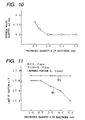
- quantity H in which the central electrode 2 is protruded from the lower end face 1D of the insulator 1 is 1.0 mm or more (1.0 ⁇ H mm).
- the central electrode 2 is protruded from the lower end face 1D of the insulator 1 if the quantity H in which the central electrode 2 is protruded from the lower end face 1D of the insulator 1 is smaller than 1.0 mm, the central electrode 2 is gradually narrowed in the direction of the end face as shown in Fig. 9B.
- the maximum value of quantity-in which the side face 2A of the central electrode 2 is wasted shall be ⁇ d.
- the maximum wasted quantity ⁇ d in case the side face of the central electrode is wasted as shown in Fig. 9B is larger than the maximum wasted quantity ⁇ d in case the side face is wasted as shown in Fig. 9A.
- spark plugs different in the protruded quantity H were prepared and semi-surface discharge from the semi-surface ground electrode 12 was respectively made '4 x 10 7 ' times (forty million times) to examine resistance to sparks.
- Fig. 10 shows the result. As clear from Fig.
- the quantity H in which the central electrode 2 is protruded is 1.0 mm or more (1.0 ⁇ H mm) to reduce the maximum wasted quantity ⁇ d.
- Each parallel ground electrode 11 of the spark plugs used for this test is cut on the face welded to the main metal shell 5.
- the wasted quantity was examined by always flying sparks in the semi-surface gap (B).
- This test was executed by installing the above spark plugs in a chamber provided with a window via which the main air gap (A) and the semi-surface gap (B) can be observed.
- the quantity H in which the central electrode 2 is protruded from the lower end face 1D of the insulator 1 is 4.0 mm or less (H ⁇ 4.0 mm). There are two reasons for it.
- FIG. 11 is a graph showing relationship between the protruded quantity H of the central electrode 2 in case the dimension in which the central electrode 2 is protruded from the end face 5D of the main metal shell 5 is fixed and air-fuel ratio (A/F) to be the limit of ignition.
- Air-fuel ratio (A/F) to be the limit of ignition is set to air-fuel ratio (A/F) the ratio of lost fire of which is 1%.
- a curve 103 shows air-fuel ratio to be the limit of ignition by a spark in the main air gap (A) and a curve 104 show air-fuel ratio to be the limit of ignition by a spark in the semi-surface gap (B).
- a straight 6-cylinder engine provided with the displacement of 2 liter. is used and the above air-fuel ratio is measured at the idle operation of 700 rpm.
- the dimension (F + H) in which the central electrode 2 of the spark plug is protruded from the end face 5D of the main metal shell 5 is set to 6.0 mm and the distance B of the semi-surface gap (B) is set to 1.7 mm.
- the curve 103 becomes a flat straight line.
- the position of a spark approaches the wall of a combustion chamber as the protruded quantity H is increased, ignitability is deteriorated and the curve 104 becomes a curve the right side of which lowers.
- the protruded quantity H of the central electrode 2 is 4.0 mm or less (H ⁇ 4.0 mm).
- Fig. 12 is a graph showing relationship between the protruded quantity H of the central electrode 2 and the temperature of the central electrode 2.
- the protruded quantity F of the insulator 1 is 3.0 mm and a spark plug the heat value of which is 5 is used.
- the protruded quantity H of the central electrode 2 is increased, the reduction of heat by the insulator 1 is deteriorated and the temperature at the end of the central electrode 2 becomes high. If the protruded quantity H is 5.0 mm, the temperature at the end of the central electrode 2 exceeds 850°C and preignition may be caused. Therefore, it is desirable that the protruded quantity H of the central electrode 2 is 4.0 mm or less (H ⁇ 4.0 mm).
- the quantity H in which the central electrode 2 is protruded from the lower end face 1D of the insulator 1 is 1.0 ⁇ H ⁇ 4.0 mm.
- Fig. 13 is a partial sectional view showing an enlarged vicinity of a central electrode 2', a parallel ground electrode 11 and a semi-surface ground electrode 12 respectively of a spark plug.
- the diameter of the end of the central electrode 2' is reduced, compared with the base protruded from the lower end face 1D of insulator 1.
- the diameter of the end of the central electrode 2' is D1 and the diameter of the base is D2.
- a chip 21 made of a platinum alloy is bonded to the end of the central electrode 2' the diameter of which is reduced by laser beam welding.
- quantity H in which the central electrode 2' is protruded from the lower end face 1D of the insulator 1 is set to 2.0 mm and quantity J in which the central electrode 2' is protruded from the lower end face 1D of the insulator 1 at a starting point 22 from which the reduction of the diameter of the central electrode 2' is started is set to 0.6 mm. (Grounds that 0.4 ⁇ D1 ⁇ 1.6 mm)
- the diameter D1 at the end of the central electrode 2' is 0.4 mm or more and 1.6 mm or less. if the diameter D1 at the end is smaller than 0.4 mm, the waste of the electrode by sparks increases even if a platinum alloy or an iridium alloy is used for the end of the central electrode 2' and it is not practical.
- Fig. 14 is a graph showing relationship between the diameter D1 at the end of the central electrode and the probability of a spark in a main air gap (A).
- a curve 105 shows the probability of a spark in the main air gap (A) at normal time which is not carbon fouling time.
- a spark plug the diameter D2 at the base of the central electrode of which is 2.6 mm, the distance A of the main air gap (A) of which is 1.1 mm and the distance B of a semi-surface gap (B) of which is 1.4 mm is used.
- the probability of a spark in the main air gap (A) is reduced from 100% when the diameter D1 at the end of the central electrode exceeds 1.6 mm at normal time and it becomes unstable in which of the main air gap (A) or the semi-surface gap (B) discharge is to be executed.
- the diameter D1 at the end of the central electrode 2' is 0.4 mm or more and 1.6 mm or less (0.4 ⁇ D1 ⁇ 1.6 mm). (Grounds that (D1 + 0.3) ⁇ D2-mm)
- the diameter D2 at the base of the central electrode 2' is thicker than the diameter D1 at the end. If the diameter D2 at the base of the central electrode is thick, more heat is reduced from the end of the central electrode and the end of the central electrode is prevented from being overheated. Therefore, it was judged that it was desirable that the diameter D2 at the base of the central electrode was larger than (the diameter D1 at the end of the central electrode + 0.3 mm).
- the upper limit of the diameter D2 at the base of the central electrode is inevitably determined by the thickness of the insulator 1 required for insulation in the vicinity of the lower end of the insulator 1. (Grounds that 2.0 ⁇ D2 mm)
- the diameter D2 at the base of the central electrode is thickened. As the concentration of electric fields is softened by thickening the diameter D2 at the base of the central electrode, the rate of the generation of sparks in the semi-surface gap (B) at normal time can be reduced.
- the diameter D2 at the base of the central electrode is 2.0 mm or more (2.0 ⁇ D2 mm). It is considered that the reason why the maximum value ⁇ d of the wasted quantity of the central electrode decreases when the diameter D2 at the base of the central electrode is thickened is that the volume of the electrode wasted per one spark is approximately fixed and that the rate of the generation of a spark in the semi-surface gap (B) can be reduced because the concentration of electric fields is reduced by thickening the diameter D2 at the base of the central electrode.
- each semi-surface ground electrode 12 As these embodiments are the same as the first and second embodiments except the shape of each semi-surface ground electrode 12, the description is omitted and only different parts will be described below.
- Fig. 15 is a partial sectional view showing a third embodiment with a central electrode 2, a parallel ground electrode 11 and a semi-surface ground electrode 12' and the vicinity of the lower end of main metal shell 5 respectively of a spark plug enlarged.
- the semi-surface ground electrode 12' is formed in the shape of a straight pole and the side is resistance-welded to the lower end face 5D of the main metal shell 5.
- Fig. 16 is a partial sectional view showing a fourth embodiment with a central electrode 2, a parallel ground electrode 11, a semi-surface ground electrode 12' and the vicinity of the lower end of main metal shell 5 respectively of a spark plug enlarged.
- the lower end face 5D is formed so that it is wide by forming a protruded part 5E protruded on the side of the inner diameter at the lower end of the main metal shell 5 and an auxiliary gap (K) is provided between the main metal shell and insulator 1.
- a semi-surface ground electrode 12' in the shape of a straight pole is resistance-welded to the lower end face 5D formed so that it is wide.
- the semi-surface ground electrode 12' is not required to be bent in approximately the shape of a letter L on the side of the central electrode 2 in the vicinity of a bonded part to the end face of the main metal shell by forming as described above, no manufacturing problem such as breakage and a crack is caused.
- the test of carbon fouling and a channeling test were made using a general spark plug (type PFR6G-11), a semi-surface spark plug (type BKR6EKUC) and the spark plugs equivalent to the first and second embodiments of the present invention.
- the reason why the spark plug according to the present invention is superior to the semi-surface spark plug is that in the case of the spark plug according to the present invention, the state of combustion is good because sparks fly in the main air gap (A) at normal time and that quantity in which incomplete combustion which causes a carbon fouling is caused is small.
- two semi-surface ground electrodes 12 are provided, however, a single semi-surface ground electrode may be also provided or multiple semi-surface ground electrodes composed of three or more may be also provided. However, as in the case of a single one, it is difficult to burn off carbon by sparks across the whole end face of insulator and cleanness by sparks is deteriorated, it is considered that it is desirable that two or three semi-surface ground electrodes are provided.
- the spark plug in which the diameter of the central electrode is not reduced (not so-called thermostat) inside the end of the insulator is described.
- the diameter of a spark plug may be also reduced at one or more stages.
- the semi-surface ground electrodes are provided in the vicinity of the lower end face of the insulator in addition to the parallel ground electrode for executing main discharge, the present invention is provided with the self-cleaning action of burning off carbon by semi-surface discharge from the semi-surface ground electrode at carbon fouling time at which the surface of the insulator is fouled by carbon and as the main discharge is executed by the parallel ground electrode, there is excellent effect that the present invention is extremely strong against carbon fouling, is provided with high ignitability, channeling is hardly caused and a long life is given.
Landscapes
- Spark Plugs (AREA)
Applications Claiming Priority (4)
| Application Number | Priority Date | Filing Date | Title |
|---|---|---|---|
| JP17962598 | 1998-06-11 | ||
| JP17962598 | 1998-06-11 | ||
| JP12450499 | 1999-04-30 | ||
| JP11124504A JP3140006B2 (ja) | 1998-06-11 | 1999-04-30 | スパークプラグ |
Publications (3)
| Publication Number | Publication Date |
|---|---|
| EP0964490A2 true EP0964490A2 (de) | 1999-12-15 |
| EP0964490A3 EP0964490A3 (de) | 2002-11-06 |
| EP0964490B1 EP0964490B1 (de) | 2005-04-20 |
Family
ID=26461187
Family Applications (1)
| Application Number | Title | Priority Date | Filing Date |
|---|---|---|---|
| EP99304555A Expired - Lifetime EP0964490B1 (de) | 1998-06-11 | 1999-06-11 | Zündkerze |
Country Status (4)
| Country | Link |
|---|---|
| US (1) | US6229253B1 (de) |
| EP (1) | EP0964490B1 (de) |
| JP (1) | JP3140006B2 (de) |
| DE (1) | DE69924786T2 (de) |
Cited By (6)
| Publication number | Priority date | Publication date | Assignee | Title |
|---|---|---|---|---|
| EP1079487A1 (de) * | 1999-08-25 | 2001-02-28 | Denso Corporation | Zündkerze für Verbrennungsmotoren |
| GB2354550A (en) * | 1999-09-22 | 2001-03-28 | Denso Corp | I.c. engine spark plug with plural spark gaps and better self-cleaning function |
| US6316868B1 (en) | 1998-12-04 | 2001-11-13 | Denso Corporation | Spark plug for internal combustion engine having better self-cleaning function |
| US6556280B1 (en) | 2000-09-19 | 2003-04-29 | Optical Switch Corporation | Period reconfiguration and closed loop calibration of an interference lithography patterning system and method of operation |
| US6956319B2 (en) | 2001-02-13 | 2005-10-18 | Denso Corporation | Structure of spark plug designed to provide higher wear resistance to center electrode and production method thereof |
| DE10340043B4 (de) * | 2003-08-28 | 2014-10-30 | Robert Bosch Gmbh | Zündkerze |
Families Citing this family (53)
| Publication number | Priority date | Publication date | Assignee | Title |
|---|---|---|---|---|
| EP1239563B1 (de) | 1999-12-13 | 2010-06-16 | Ngk Spark Plug Co., Ltd. | Zündkerze |
| JP4532009B2 (ja) * | 2001-03-23 | 2010-08-25 | 日本特殊陶業株式会社 | スパークプラグ |
| JP4840839B2 (ja) * | 2003-12-19 | 2011-12-21 | 日本特殊陶業株式会社 | スパークプラグ |
| EP1544970B1 (de) | 2003-12-19 | 2007-05-16 | Ngk Spark Plug Co., Ltd | Zündkerze |
| JP2005183189A (ja) * | 2003-12-19 | 2005-07-07 | Ngk Spark Plug Co Ltd | スパークプラグ |
| JP4360271B2 (ja) | 2004-05-31 | 2009-11-11 | 株式会社デンソー | スパークプラグ |
| JP2006049206A (ja) | 2004-08-06 | 2006-02-16 | Denso Corp | 内燃機関用スパークプラグ |
| JP2006114476A (ja) | 2004-09-14 | 2006-04-27 | Denso Corp | 内燃機関用のスパークプラグ |
| JP2006085941A (ja) | 2004-09-14 | 2006-03-30 | Denso Corp | 内燃機関用のスパークプラグ |
| JP2006085997A (ja) * | 2004-09-15 | 2006-03-30 | Denso Corp | 内燃機関用のスパークプラグ |
| FR2892240B1 (fr) * | 2005-10-18 | 2010-10-22 | Renault Sas | Bougies d'allumage pour le moteur a combustion interne d'un vehicule automobile |
| US7877189B2 (en) * | 2005-11-30 | 2011-01-25 | Ford Global Technologies, Llc | Fuel mass control for ethanol direct injection plus gasoline port fuel injection |
| US7357101B2 (en) * | 2005-11-30 | 2008-04-15 | Ford Global Technologies, Llc | Engine system for multi-fluid operation |
| US7302933B2 (en) * | 2005-11-30 | 2007-12-04 | Ford Global Technologies Llc | System and method for engine with fuel vapor purging |
| US7406947B2 (en) | 2005-11-30 | 2008-08-05 | Ford Global Technologies, Llc | System and method for tip-in knock compensation |
| US7412966B2 (en) | 2005-11-30 | 2008-08-19 | Ford Global Technologies, Llc | Engine output control system and method |
| US7647916B2 (en) * | 2005-11-30 | 2010-01-19 | Ford Global Technologies, Llc | Engine with two port fuel injectors |
| US7730872B2 (en) | 2005-11-30 | 2010-06-08 | Ford Global Technologies, Llc | Engine with water and/or ethanol direct injection plus gas port fuel injectors |
| US8132555B2 (en) | 2005-11-30 | 2012-03-13 | Ford Global Technologies, Llc | Event based engine control system and method |
| US7594498B2 (en) * | 2005-11-30 | 2009-09-29 | Ford Global Technologies, Llc | System and method for compensation of fuel injector limits |
| US7640912B2 (en) * | 2005-11-30 | 2010-01-05 | Ford Global Technologies, Llc | System and method for engine air-fuel ratio control |
| US8434431B2 (en) * | 2005-11-30 | 2013-05-07 | Ford Global Technologies, Llc | Control for alcohol/water/gasoline injection |
| US7293552B2 (en) | 2005-11-30 | 2007-11-13 | Ford Global Technologies Llc | Purge system for ethanol direct injection plus gas port fuel injection |
| US7395786B2 (en) * | 2005-11-30 | 2008-07-08 | Ford Global Technologies, Llc | Warm up strategy for ethanol direct injection plus gasoline port fuel injection |
| US7533651B2 (en) | 2006-03-17 | 2009-05-19 | Ford Global Technologies, Llc | System and method for reducing knock and preignition in an internal combustion engine |
| US7647899B2 (en) * | 2006-03-17 | 2010-01-19 | Ford Global Technologies, Llc | Apparatus with mixed fuel separator and method of separating a mixed fuel |
| US7665428B2 (en) | 2006-03-17 | 2010-02-23 | Ford Global Technologies, Llc | Apparatus with mixed fuel separator and method of separating a mixed fuel |
| US7581528B2 (en) | 2006-03-17 | 2009-09-01 | Ford Global Technologies, Llc | Control strategy for engine employng multiple injection types |
| US8267074B2 (en) * | 2006-03-17 | 2012-09-18 | Ford Global Technologies, Llc | Control for knock suppression fluid separator in a motor vehicle |
| US8015951B2 (en) * | 2006-03-17 | 2011-09-13 | Ford Global Technologies, Llc | Apparatus with mixed fuel separator and method of separating a mixed fuel |
| US7389751B2 (en) * | 2006-03-17 | 2008-06-24 | Ford Global Technology, Llc | Control for knock suppression fluid separator in a motor vehicle |
| US7665452B2 (en) * | 2006-03-17 | 2010-02-23 | Ford Global Technologies, Llc | First and second spark plugs for improved combustion control |
| US7779813B2 (en) * | 2006-03-17 | 2010-08-24 | Ford Global Technologies, Llc | Combustion control system for an engine utilizing a first fuel and a second fuel |
| US7740009B2 (en) * | 2006-03-17 | 2010-06-22 | Ford Global Technologies, Llc | Spark control for improved engine operation |
| US7255080B1 (en) | 2006-03-17 | 2007-08-14 | Ford Global Technologies, Llc | Spark plug heating for a spark ignited engine |
| US7933713B2 (en) * | 2006-03-17 | 2011-04-26 | Ford Global Technologies, Llc | Control of peak engine output in an engine with a knock suppression fluid |
| US7578281B2 (en) * | 2006-03-17 | 2009-08-25 | Ford Global Technologies, Llc | First and second spark plugs for improved combustion control |
| US7681554B2 (en) * | 2006-07-24 | 2010-03-23 | Ford Global Technologies, Llc | Approach for reducing injector fouling and thermal degradation for a multi-injector engine system |
| US7287509B1 (en) | 2006-08-11 | 2007-10-30 | Ford Global Technologies Llc | Direct injection alcohol engine with variable injection timing |
| US7909019B2 (en) * | 2006-08-11 | 2011-03-22 | Ford Global Technologies, Llc | Direct injection alcohol engine with boost and spark control |
| US7461628B2 (en) | 2006-12-01 | 2008-12-09 | Ford Global Technologies, Llc | Multiple combustion mode engine using direct alcohol injection |
| US8091352B2 (en) | 2006-12-28 | 2012-01-10 | Caterpillar Inc. | Ignition system |
| US7676321B2 (en) * | 2007-08-10 | 2010-03-09 | Ford Global Technologies, Llc | Hybrid vehicle propulsion system utilizing knock suppression |
| US8214130B2 (en) | 2007-08-10 | 2012-07-03 | Ford Global Technologies, Llc | Hybrid vehicle propulsion system utilizing knock suppression |
| US7971567B2 (en) | 2007-10-12 | 2011-07-05 | Ford Global Technologies, Llc | Directly injected internal combustion engine system |
| US8118009B2 (en) * | 2007-12-12 | 2012-02-21 | Ford Global Technologies, Llc | On-board fuel vapor separation for multi-fuel vehicle |
| US8550058B2 (en) | 2007-12-21 | 2013-10-08 | Ford Global Technologies, Llc | Fuel rail assembly including fuel separation membrane |
| US8141356B2 (en) * | 2008-01-16 | 2012-03-27 | Ford Global Technologies, Llc | Ethanol separation using air from turbo compressor |
| US7845315B2 (en) | 2008-05-08 | 2010-12-07 | Ford Global Technologies, Llc | On-board water addition for fuel separation system |
| JP5751137B2 (ja) | 2011-11-01 | 2015-07-22 | 株式会社デンソー | 内燃機関用のスパークプラグ及びその取付構造 |
| JP5870629B2 (ja) * | 2011-11-02 | 2016-03-01 | 株式会社デンソー | 内燃機関用のスパークプラグ及びその取付構造 |
| JP5721680B2 (ja) * | 2012-09-27 | 2015-05-20 | 日本特殊陶業株式会社 | スパークプラグ |
| DE102018222460A1 (de) * | 2018-12-20 | 2020-06-25 | Robert Bosch Gmbh | Zündkerze mit verrundetem Isolatorfuß-Abschnitt |
Family Cites Families (9)
| Publication number | Priority date | Publication date | Assignee | Title |
|---|---|---|---|---|
| DE2205720A1 (de) * | 1972-02-08 | 1973-08-23 | Bosch Gmbh Robert | Hochspannungszuendkerze fuer brennkraftmaschinen |
| JPS49120932A (de) | 1973-03-22 | 1974-11-19 | ||
| JPS5859580A (ja) | 1981-10-01 | 1983-04-08 | 株式会社デンソー | 内燃機関用点火プラグ |
| JPS5971279A (ja) | 1982-10-13 | 1984-04-21 | 日本特殊陶業株式会社 | 背後電極型点火プラグ |
| JPS6081784A (ja) | 1983-10-11 | 1985-05-09 | 日本特殊陶業株式会社 | スパ−クプラグ |
| JPS60180082A (ja) | 1984-02-25 | 1985-09-13 | 日本特殊陶業株式会社 | 副燃焼室を備えた内燃機関用スパ−クプラグ |
| JP3011249B2 (ja) | 1992-05-22 | 2000-02-21 | 日本特殊陶業株式会社 | スパークプラグ |
| JP3368635B2 (ja) | 1993-11-05 | 2003-01-20 | 株式会社デンソー | スパ−クプラグ |
| JPH10189212A (ja) | 1995-11-15 | 1998-07-21 | Ngk Spark Plug Co Ltd | 多極スパークプラグ |
-
1999
- 1999-04-30 JP JP11124504A patent/JP3140006B2/ja not_active Expired - Lifetime
- 1999-06-10 US US09/329,311 patent/US6229253B1/en not_active Expired - Lifetime
- 1999-06-11 EP EP99304555A patent/EP0964490B1/de not_active Expired - Lifetime
- 1999-06-11 DE DE69924786T patent/DE69924786T2/de not_active Expired - Lifetime
Cited By (8)
| Publication number | Priority date | Publication date | Assignee | Title |
|---|---|---|---|---|
| US6316868B1 (en) | 1998-12-04 | 2001-11-13 | Denso Corporation | Spark plug for internal combustion engine having better self-cleaning function |
| EP1079487A1 (de) * | 1999-08-25 | 2001-02-28 | Denso Corporation | Zündkerze für Verbrennungsmotoren |
| GB2354550A (en) * | 1999-09-22 | 2001-03-28 | Denso Corp | I.c. engine spark plug with plural spark gaps and better self-cleaning function |
| US6552476B1 (en) | 1999-09-22 | 2003-04-22 | Denso Corporation | Spark plug for internal combustion engine having better self-cleaning function |
| GB2354550B (en) * | 1999-09-22 | 2004-02-04 | Denso Corp | Spark plug for internal combustion engine having better self-cleaning function |
| US6556280B1 (en) | 2000-09-19 | 2003-04-29 | Optical Switch Corporation | Period reconfiguration and closed loop calibration of an interference lithography patterning system and method of operation |
| US6956319B2 (en) | 2001-02-13 | 2005-10-18 | Denso Corporation | Structure of spark plug designed to provide higher wear resistance to center electrode and production method thereof |
| DE10340043B4 (de) * | 2003-08-28 | 2014-10-30 | Robert Bosch Gmbh | Zündkerze |
Also Published As
| Publication number | Publication date |
|---|---|
| DE69924786T2 (de) | 2006-03-09 |
| EP0964490B1 (de) | 2005-04-20 |
| JP3140006B2 (ja) | 2001-03-05 |
| JP2000068032A (ja) | 2000-03-03 |
| US6229253B1 (en) | 2001-05-08 |
| EP0964490A3 (de) | 2002-11-06 |
| DE69924786D1 (de) | 2005-05-25 |
Similar Documents
| Publication | Publication Date | Title |
|---|---|---|
| EP0964490B1 (de) | Zündkerze | |
| EP0171994B1 (de) | Zündkerze | |
| EP1102373B1 (de) | Zündkerze | |
| WO2009039478A2 (en) | Spark plug structure for improved ignitability | |
| JP2008123989A (ja) | 内燃機関用スパークプラグ | |
| JP4270784B2 (ja) | スパークプラグ | |
| US9000658B2 (en) | Spark plug for internal combustion engine | |
| EP0535584B1 (de) | Zündkerze und sein Herstellungsverfahren | |
| US7170219B2 (en) | Spark plug with multiple ground electrodes | |
| US7408294B2 (en) | Spark plug with high capability to ignite air-fuel mixture | |
| US5502352A (en) | Spark plug having horizontal discharge | |
| EP0989645B1 (de) | Zündkerze | |
| JP2727558B2 (ja) | 内燃機関用スパークプラグ | |
| JP2013098086A (ja) | 内燃機関用のスパークプラグ及びその取付構造 | |
| US6573641B2 (en) | Spark plug | |
| KR20100127236A (ko) | 스파크 플러그 | |
| JP4398483B2 (ja) | スパークプラグ | |
| JP2006073205A (ja) | スパークプラグ | |
| JP4457021B2 (ja) | スパークプラグ | |
| US7541724B2 (en) | Spark plug requiring low discharge voltage and having high self-cleaning capability | |
| JP2000294360A (ja) | スパークプラグ | |
| JPH07272826A (ja) | スパークプラグ | |
| JP2001237046A (ja) | スパークプラグ | |
| KR100701570B1 (ko) | 내연기관용 점화 플러그의 전극 구조 및 전극 제조방법 | |
| JP3699490B2 (ja) | スパークプラグ |
Legal Events
| Date | Code | Title | Description |
|---|---|---|---|
| PUAI | Public reference made under article 153(3) epc to a published international application that has entered the european phase |
Free format text: ORIGINAL CODE: 0009012 |
|
| AK | Designated contracting states |
Kind code of ref document: A2 Designated state(s): AT BE CH CY DE DK ES FI FR GB GR IE IT LI LU MC NL PT SE |
|
| AX | Request for extension of the european patent |
Free format text: AL;LT;LV;MK;RO;SI |
|
| PUAL | Search report despatched |
Free format text: ORIGINAL CODE: 0009013 |
|
| AK | Designated contracting states |
Kind code of ref document: A3 Designated state(s): AT BE CH CY DE DK ES FI FR GB GR IE IT LI LU MC NL PT SE |
|
| AX | Request for extension of the european patent |
Free format text: AL;LT;LV;MK;RO;SI |
|
| 17P | Request for examination filed |
Effective date: 20030402 |
|
| AKX | Designation fees paid |
Designated state(s): DE FR GB |
|
| 17Q | First examination report despatched |
Effective date: 20030909 |
|
| GRAP | Despatch of communication of intention to grant a patent |
Free format text: ORIGINAL CODE: EPIDOSNIGR1 |
|
| GRAS | Grant fee paid |
Free format text: ORIGINAL CODE: EPIDOSNIGR3 |
|
| GRAA | (expected) grant |
Free format text: ORIGINAL CODE: 0009210 |
|
| AK | Designated contracting states |
Kind code of ref document: B1 Designated state(s): DE FR GB |
|
| REG | Reference to a national code |
Ref country code: GB Ref legal event code: FG4D |
|
| REG | Reference to a national code |
Ref country code: IE Ref legal event code: FG4D |
|
| REF | Corresponds to: |
Ref document number: 69924786 Country of ref document: DE Date of ref document: 20050525 Kind code of ref document: P |
|
| PLBE | No opposition filed within time limit |
Free format text: ORIGINAL CODE: 0009261 |
|
| STAA | Information on the status of an ep patent application or granted ep patent |
Free format text: STATUS: NO OPPOSITION FILED WITHIN TIME LIMIT |
|
| ET | Fr: translation filed | ||
| 26N | No opposition filed |
Effective date: 20060123 |
|
| REG | Reference to a national code |
Ref country code: FR Ref legal event code: PLFP Year of fee payment: 18 |
|
| REG | Reference to a national code |
Ref country code: FR Ref legal event code: PLFP Year of fee payment: 19 |
|
| REG | Reference to a national code |
Ref country code: FR Ref legal event code: PLFP Year of fee payment: 20 |
|
| PGFP | Annual fee paid to national office [announced via postgrant information from national office to epo] |
Ref country code: DE Payment date: 20180530 Year of fee payment: 20 |
|
| PGFP | Annual fee paid to national office [announced via postgrant information from national office to epo] |
Ref country code: FR Payment date: 20180511 Year of fee payment: 20 |
|
| PGFP | Annual fee paid to national office [announced via postgrant information from national office to epo] |
Ref country code: GB Payment date: 20180606 Year of fee payment: 20 |
|
| REG | Reference to a national code |
Ref country code: DE Ref legal event code: R071 Ref document number: 69924786 Country of ref document: DE |
|
| REG | Reference to a national code |
Ref country code: GB Ref legal event code: PE20 Expiry date: 20190610 |
|
| PG25 | Lapsed in a contracting state [announced via postgrant information from national office to epo] |
Ref country code: GB Free format text: LAPSE BECAUSE OF EXPIRATION OF PROTECTION Effective date: 20190610 |