EP0964189A2 - Joint plat en matière tendre et à bord revêtu - Google Patents
Joint plat en matière tendre et à bord revêtu Download PDFInfo
- Publication number
- EP0964189A2 EP0964189A2 EP99111156A EP99111156A EP0964189A2 EP 0964189 A2 EP0964189 A2 EP 0964189A2 EP 99111156 A EP99111156 A EP 99111156A EP 99111156 A EP99111156 A EP 99111156A EP 0964189 A2 EP0964189 A2 EP 0964189A2
- Authority
- EP
- European Patent Office
- Prior art keywords
- mils
- edge
- coating
- length
- gasket
- Prior art date
- Legal status (The legal status is an assumption and is not a legal conclusion. Google has not performed a legal analysis and makes no representation as to the accuracy of the status listed.)
- Granted
Links
Images


Classifications
-
- F—MECHANICAL ENGINEERING; LIGHTING; HEATING; WEAPONS; BLASTING
- F16—ENGINEERING ELEMENTS AND UNITS; GENERAL MEASURES FOR PRODUCING AND MAINTAINING EFFECTIVE FUNCTIONING OF MACHINES OR INSTALLATIONS; THERMAL INSULATION IN GENERAL
- F16J—PISTONS; CYLINDERS; SEALINGS
- F16J15/00—Sealings
- F16J15/02—Sealings between relatively-stationary surfaces
- F16J15/06—Sealings between relatively-stationary surfaces with solid packing compressed between sealing surfaces
- F16J15/10—Sealings between relatively-stationary surfaces with solid packing compressed between sealing surfaces with non-metallic packing
- F16J15/12—Sealings between relatively-stationary surfaces with solid packing compressed between sealing surfaces with non-metallic packing with metal reinforcement or covering
- F16J15/121—Sealings between relatively-stationary surfaces with solid packing compressed between sealing surfaces with non-metallic packing with metal reinforcement or covering with metal reinforcement
- F16J15/122—Sealings between relatively-stationary surfaces with solid packing compressed between sealing surfaces with non-metallic packing with metal reinforcement or covering with metal reinforcement generally parallel to the surfaces
- F16J15/123—Details relating to the edges of the packing
-
- F—MECHANICAL ENGINEERING; LIGHTING; HEATING; WEAPONS; BLASTING
- F16—ENGINEERING ELEMENTS AND UNITS; GENERAL MEASURES FOR PRODUCING AND MAINTAINING EFFECTIVE FUNCTIONING OF MACHINES OR INSTALLATIONS; THERMAL INSULATION IN GENERAL
- F16J—PISTONS; CYLINDERS; SEALINGS
- F16J15/00—Sealings
- F16J15/02—Sealings between relatively-stationary surfaces
- F16J15/06—Sealings between relatively-stationary surfaces with solid packing compressed between sealing surfaces
- F16J15/10—Sealings between relatively-stationary surfaces with solid packing compressed between sealing surfaces with non-metallic packing
- F16J15/104—Sealings between relatively-stationary surfaces with solid packing compressed between sealing surfaces with non-metallic packing characterised by structure
Definitions
- Gaskets having an edge coating on at least one vertical edge (lying between the two faces of the gasket) of the gasket is provided.
- the edge coating provides a much greater sealing ability to soft gasket material.
- the present invention offers gasket edge coatings which are optimized and thus improved. Edge coatings can be put on gaskets to intentionally obtain a total seal against fluids.
- the sealing ability of soft gasket materials is extremely important, and has been the focus of considerable development effort.
- the edge coating is one feature which has recently been developed to provide a greater sealing ability to the gasket.
- the edge coating allows the remainder of the gasket to optionally and preferably have no coating. When the gasket is uncoated, or has only a release coating, the compression failure resistance of the gasket is preserved.
- Beading on the face of the gasket is known. Such beading is a raised area put on the face. Beading, however, does not extend past the edge, and does not extend onto the edge. Although the beading is used to enhance sealing ability, the beading fails to consistently provide a perfect seal.
- gasket reference relies on coatings to provide or enhance the sealing ability of the gasket.
- U.S. 4,499,135 impregnates the gasket with a silicone resin to improve resistance to water/antifreeze mixtures
- U.S. 3,661,401 requires that the gasketing is given a coating which covers the entire gasket, vertical edges included
- U.S. 4,600,201 impregnates the gasket mat with a polymerizable liquid impregnating agent and applying to at least one part of at least one mat face, a coating containing a polymerizable polymer material.
- Gasketing which is completely coated in general will perform poorly at higher pressures, which severely limits the field of use of the gaskets.
- a soft gasket material comprises two opposed surfaces (faces), and at least one edge which is substantially perpendicular to these surfaces; the edge (referred to herein as the perpendicular edge of the gasket) further has a coat thereon which extends directly from the edge at its center point and going to the coat's outer surface (referred to herein as "thickness length B").
- the center point of the edge is the middle of the edge length.
- the edge length is the shortest distance on the edge going between the two faces in a straight line.
- the coat is also required to have a width in the direction parallel to the edge such that the coat covers the edge from side to side and extends past at least one corner of the edge in an amount effective to form a barrier against the passage of fluids onto the face of the gasket.
- the corner being where the edge meets one of the opposed surfaces, i.e. the end of the edge).
- the length or distance that the coating extends past the corner of the edge (or the end of the edge) in a direction perpendicular to the opposed surfaces is referred to herein as a "lip”, the "extended coating”, “extended coating”, the “protruding length”, the “protruding distance” and is also called “protruding length A”.
- the “coat thickness” or “thickness length B” refers to the length or distance in the coating which extends directly from the gasket edge at its middle point between the opposed surfaces and ending at the outer surface of the coat.
- the gasket provides support to the protruding lip (or extended coating).
- the ratio of A:B must be a minimum of about 0.6 and preferably it is a minimum of about 0.9.
- the thickness length B is a distance of at least about 0.06 mm (2 mils).
- the thickness length B is a minimum length of about 0.08 mm (3 mils) and the ratio of A:B is a minimum of about 0.8 and preferably is a minimum of about 1.25.
- the thickness length B provides a base for the coating which forms protruding length A.
- the coating When the coated edge is around an aperture in the gasket sheet material, the coating forms a "primary seal" against the passage of fluids going from the aperture and across the face of the gasket. When the coated edge is around the outside or the perimeter of the gasket, the coating forms a secondary seal against fluids.
- the coated edge can be either around an aperture or it can be around the outside of the gasket.
- Fig. 1 shows a gasket sheet having edge 2 and opposed faces 1 and 7.
- the gasket sheet edge 2 has a coating 5 which is an edge seal.
- the edge seal coating extends beyond the plane of each face in a direction perpendicular to the face.
- the coating extends a distance 3 herein referred to as protruding length A which is at least about 0.06 mm (2.4 mils) past the face.
- protruding length A which is at least about 0.06 mm (2.4 mils) past the face.
- protruding length A which is at least about 0.06 mm (2.4 mils) past the face.
- protruding length A which is at least about 0.06 mm (2.4 mils) past the face.
- protruding length A which is at least about 0.06 mm (2.4 mils) past the face.
- protruding length A which is at least about 0.06 mm (2.4 mils) past the face.
- protruding length A is at least about 0.06 mm (2.4 mils
- Protruding length A should be present on each side of the gasket where face 1 or 7 meets edge 2.
- the coating also extends a distance 4 out from the surface of the edge 2 (measured at a point on the edge which is equidistant from each face).
- Distance 4, herein referred to as thickness length B is the distance (on Fig. 1) from the center of edge 2 directly to the outer surface of the coating 5.
- the ratio of the protruding length A : thickness length B should be at least about 0.8, and the thickness length B is at least about 0.08 mm (3 mils).
- Fig. 2 shows a gasket sheet having edge 2 and opposed faces 1 and 7.
- the gasket sheet edge 2 has a coating 9 which is an edge seal. From the figure it can be appreciated that each face has a plane, and the edge seal coating extends beyond the plane of each face in a perpendicular direction.
- the coating 9 extends a distance 3, herein referred to as protruding length A.
- the coating here extends past the corner and the plane of each face, since the corner is in the plane of the face.
- the coating also extends a distance 4 herein referred to as thickness length B which is the distance from the center of edge 2 directly to the outer surface of the coating 9.
- Coating 9 extends out onto faces 1 and 7 in optional features 6 and 8 but the extended coating barrier does not rest on the gasket face, so the ratio of length A : length B must be at least 0.8.
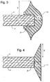
- Fig. 3 shows a gasket sheet having edge 2 and opposed faces 1 and 7.
- the gasket sheet edge 2 has a coating 10 which is an edge seal.
- the edge seal coating extends beyond the plane of each face in a direction which is perpendicular to the face (shown in Fig. 3 as distance 3). This protruding length A of the coating rests in part (along distance C) on the face of the gasket.
- the coating also extends a distance 4 herein referred to as thickness length B which is the distance from the center of edge 2 directly to the outer surface of the coating 10.
- the edge coating overlaps the end of the edge and, overlapping the corner, extends onto a face of the gasket.
- Thickness length B must be at least about 0.06 mm (2 mils) and the ratio of length A : length B must be at least about 0.6. Since part of the edge coating is supported (along distance C) by the face of the gasket the ratio of length A : length B can be lower than the edge coatings of Fig. 1, 2, and 4. Permissively, the coating can extend onto one or both gasket faces. Such coatings form a barrier against the passage of fluids, and do not form a level coating over the gasket.
- Fig. 4 shows a gasket sheet having edge 2 and opposed faces 1 and 7.
- the gasket sheet edge 2 has a coating 11 which is an edge seal.
- the edge seal coating extends beyond the plane of each face in a perpendicular direction.
- the coating extends a distance 3 which is protruding length A.
- the thickness of the coating at the middle of the edge is indicated by distance 4 (thickness length B).
- Fig. 5 shows a gasket sheet having a coated edge.
- the coating extends beyond the plane of each face in a perpendicular direction.
- An extended coating is thus present at each side of the coated edge; arbitrarily, the figure shows a protruding length A 1 at the upper face and a protruding length A 2 at the other (lower) face. Neither of the protruding lengths of coating rest on either of gasket faces.
- Fig. 6 shows a gasket sheet having a coated edge.
- the coating extends beyond the plane of each face in a perpendicular direction and forms protruding length A 1 which extends perpendicular to the upper face, and protruding length A 2 which extends perpendicular to the lower face; both length A 1 and A 2 rests in part on the face of the gasket. It can also be noted that the coating covers the entire edge of the gasket and extends out onto the face of the gasket.
- Fig. 7 shows a gasket sheet having a coated edge.
- the coating extends beyond the plane of each face in a perpendicular direction and forms protruding length A 1 going beyond the upper face, and protruding length A 2 which extends beyond the lower face.
- Each of the protruding lengths (A 1 and A 2 ) rest in part on one of the faces of the gasket. It can also be noted that the coating on the gasket edge covers the entire edge of the gasket and extends out onto both of the faces of the gasket.
- the faces or facial surfaces 1 (the "upper” face) and 7 (the “lower” face) of the gaskets in the above figures each have a facial plane.
- the facial planes are substantially parallel to each other.
- the facial plane goes through the corner between the face and the edge 2 which is substantially perpendicular to each.
- the edge surface is around an aperture and is given the coating which extends or protrudes beyond the facial plane.
- the edge coatings of the present invention have two basic structures: 1) one where the lip or extended coating barrier is partially supported by the gasket face (as it is in Fig. 3, 6, and 7), and 2) one where the coating merely extends past the corner between the edge and the face (as in Fig. 1, 2, 4, and 5) where the coating is not resting on or supported by the face.
- the lip of the coating (protruding length A) must extend past at least one corner of the edge in an amount effective to form a barrier against the passage of fluids onto the face of the gasket.
- the distance that protruding length A must extend past the barrier will depend on the structure of the coating.
- the minimum length of thickness length B should not be less than about 0.06 mm (2 mils), and protruding length A must be at least about 0.08 mm (3 mils), and preferably A is at least about 0.25 mm (10 mils).
- protruding length A is in the range of from about 0.08 mm (3 mils) to about 3.8 mm (150 mils), and preferably it is in the range of from about 0.25 mm (10 mils) to about 2,5 mm (100 mils).
- protruding length A When the lip of the coating does not rest on the face, in order to obtain a gasket which can give a perfect seal across this coated edge the protruding length A must be at least about 0.1 mm (4 mils), but the minimum length of thickness length B, however must be least about 0.08 mm (3 mils), and the ratio of protruding length A to thickness length B being at least about 0.8 and preferably is at least about 2.
- protruding length A is at least about 0.13 mm (5 mils) long and more preferably is at least about 0.25 mm (10 mils) long.
- protruding length A is in the range of from about 0.1 mm (4 mils) to about 3.8 mm (150 mils), and preferably it is in the range of from about 0.25 mm (10 mils) to about 3.2 mm (125 mils).
- the ratio of the protruding length A (distance 4) to the thickness B (distance 3) can be as low as about 0.6 (a minimum of 0.6).
- the ratio can be in the range of from about 0.6 to about 10.
- the ratio should be a minimum of about 0.8 or more and preferably it is at least about 2 or more.
- the ratio should be in the range of from about 0.8 to about 20.
- thickness length B can be from about 0.06 mm (2 mils) to about 1.3 mm (50 mils) and preferably it is from about 0.25 mm (10 mils) to about 1 mm (40 mils) long.
- distance C that the coating extends onto the gasket face can be a minimum of about 0.025 mm (1 mil), and preferably a minimum of about 0.13 mm (5 mils); acceptably it is in the range of from about 0.025 mm (1 mil) to about 6.4 mm (250 mils) long.
- thickness length B can be in the range of from about 0.08 mm (3 mils) to about 1.3 mm (50 mils) long, and preferably it is from about 0.25 mm (10 mils) to about 1 mm (40 mils) long.
- edge coatings of the present invention are required to be within a specific ratio range of: protruding length A / thicknees length B in order to provide better barriers for sealing against fluid leaks. (In Fig. 1 and 2 this is shown to be distance 3 over distance 4.)
- the edge coatings of the present invention are used on the vertical edges of soft gasket sheet materials. Such soft gasket sheet materials are porous and compressible.
- the edge coatings are put onto the edge or edges as needed to seal off the gasket against the passage of fluids both into the gasket sheet and across the edge onto the face of the gasket.
- an entire edge is coated, although it is not necessary if an adequate seal is provided by coating merely a portion of the edge; for example, if bolt areas are near an aperture's edge the coating could be optional, and thus omitted, near the bolt.
- a completely coated gasket can take advantage of the sealing ability provided by the wide-edge edge coatings of the instant invention, although in some embodiments, to preserve compression failure resistance, the total amount of coating covering the gasket faces is preferably limited to cover only a portion of the gasket, the rest of the gasket being left uncoated. Preferably, to preserve compression failure resistance, a coating will cover up to about 50% of the gasket, and even more preferably, it is limited to cover a maximum of about 30% of the gasket.
- Soft gasket materials are preferred for use with the wide-edge coating of the present invention.
- Many types of soft gasket materials comprise fiber and a binder; filler is preferably added.
- Such soft gasket materials are porous and compressible.
- the cut gasket edges, being porous are ideal for edge coating since this will help to seal the flow of fluids from the gasket by either penetrating or at least closing off the pores.
- a face and the corner between the edge and the face will be in one plane (which goes through both).
- a facial area can be forced into a different plane than the rest of the face.
- the corner between the face and the edge may become rounded and it may be more difficult to detect the location of the corner or the facial plane which goes through the corner.
- the corner which the coating should protrude past can be located by noting the point where the cut portion of the edge ends. This is the point of the corner which the coating should protrude past.
- the cut-portion of the edge typically contains more pores than the surface of either gasket face and is also distinctive in appearance by showing a cross-section of the materials inside the gasket. Protruding length A would then be measured from the corner, or from the corner plane that goes through the corner.
- Gaskets with the sealing edge coatings of the present invention successfully give an excellent to a total seal.
- Flange pressures can be used which are down to 17.3 N/cm 2 (25 PSI), although since it is easier to get an excellent to total seal higher flange pressures, it is preferred to use flange pressures of at least about 207 N/cm 2 (300 PSI) or more. A total seal is found where the coating will completely prevent fluids from leaking past the aperture, across the face of the gasket and also through the gasket sheet.
- the coating can be put on in any film-forming manner such as, for example, dipping, melting or painting the exposed edge while protecting any gasket portions not to be coated.
- a coating is put on an aperture edge by placing a plurality of gasket sheets together so that a cavity is formed from the apertures of the plurality of gasket sheets, and then contacting the edges of the aperture on each gasket sheet with a coating material so that the edges become coated in an amount effective to achieve a substantial sealing of the gasket along the edge of the aperture where the edge is coated.
- Separate non-gasket sheets (spacers) having the same configuration as the gasket can be placed between the individual gasket sheets so that the coating can form and extend past the corner of the gasket forming protruding length A (distance 3).
- the coating used deforms or stretches while it is wet or before it becomes completely solid. Then, when the gaskets are separated before the coating on the edge becomes solid, the coating is pulled and stretches so that the protruding length A will form.
- One coating which is particularly good for this is an acrylic latex polymer.
- the gasket sheets have at least one other spacer sheet in between the two gasket sheets.
- Such other sheets in between the gasket sheets are "spacers" to separate the gaskets from each other. These spacers allow a separation between each gasket sheet to permit the protruding length A to form.
- the spacer sheets will also have apertures, but the apertures can be wider, smaller, or the same size as the apertures of the gaskets. When the spacer has a wider aperture than the gasket, a portion of the gasket sheet face is exposed and the coating material can contact and coat the face where it is exposed around the aperture.
- the one or both faces is exposed in an amount effective to permit the coating to contact the exposed face, then a protruding length is formed which rests in part on the gasket face.
- the gasket face around the edge is exposed to the coating in an amount of at least about 0.13 mm (5 mils); more preferably the gasket is exposed to the coating at an amount of at least about 0.2 mm (8 mils).
- any vertical edge between the opposed faces of a gasket sheet material can be given a coating, including the edge which forms the outer perimeter of the gasket.
- the coating can be organic, inorganic, or inorganic/organic hybrid polymers as well as filled polymers. When the vertical edge is one which encounters fluids during use, however, a polymer coating is particularly useful and preferred.
- the polymer coating materials are coatings selected from the group consisting of acrylic, acrylonitrile, polyvinylidene chloride, fluorosilicone, polyurethane, acrylonitrile butadiene rubber (NBR), fluoro polymers, hydrogenated NBR, silicone rubber coatings (both UV curable, heat curable, and room temperature curable), styrene butadiene polymer, fluoroelastomer polymer, fluorosilicone polymer, acrylic-acrylonitrile polymer, carboxylated acrylonitrile polymer, chloroprene rubber polymer, ethylene propylene rubber polymer, ethylene/vinyl acetate, epoxy, and mixtures thereof. Any latex can be used.
- Identical annular gaskets were cut from a cellulose based paper gasket sheet material. Each gasket was a circle and had the following measurements: ring inner diameter 6.4 cm (2.5 inches) (from one side of the aperture to the other), ring outer diameter 9.5 cm (3.75 inches), thickness 0.8 mm (31 mils). The gaskets all had the inner vertical edge of the aperture coated with an acrylic latex for the gasket samples.
- the thickness length B (indicated as the distance of 4 in Fig. 1 and 2) and the protruding length A (indicated as the distance of 3 in Fig. 1 and 2) are indicated as "length B" and "length A" for each gasket in each of the Examples.
- the EMALT seal test indicates the sealing ability of the gasket tested.
- the gasket samples were put into a cylinder which could be pressurized with nitrogen.
- the flange pressure was at 207 N/cm 2 (300 PSI)
- the nitrogen pressure in the cylinder was brought up to 9.7 N/cm 2 (14 pounds per square inch (PSI)), and the number of minutes that elapsed while the pressure decayed to 9.0 N/cm 2 (13 PSI) was measured. The longer it takes for the pressure to drop the better the seal.
- Examples 1 to 11 the EMALT results are total seal. In Examples 12 to 18 the seal is indicated as a psi/min leakage rate.
Landscapes
- Engineering & Computer Science (AREA)
- General Engineering & Computer Science (AREA)
- Mechanical Engineering (AREA)
- Gasket Seals (AREA)
- Sealing Material Composition (AREA)
Applications Claiming Priority (2)
| Application Number | Priority Date | Filing Date | Title |
|---|---|---|---|
| US09/093,084 US6241253B1 (en) | 1998-06-08 | 1998-06-08 | Edge coated soft gasket |
| US93084 | 1998-06-08 |
Publications (3)
| Publication Number | Publication Date |
|---|---|
| EP0964189A2 true EP0964189A2 (fr) | 1999-12-15 |
| EP0964189A3 EP0964189A3 (fr) | 2000-10-25 |
| EP0964189B1 EP0964189B1 (fr) | 2003-08-27 |
Family
ID=22236936
Family Applications (1)
| Application Number | Title | Priority Date | Filing Date |
|---|---|---|---|
| EP99111156A Expired - Lifetime EP0964189B1 (fr) | 1998-06-08 | 1999-06-08 | Joint plat en matière tendre et à bord revêtu |
Country Status (10)
| Country | Link |
|---|---|
| US (1) | US6241253B1 (fr) |
| EP (1) | EP0964189B1 (fr) |
| JP (1) | JP2000028004A (fr) |
| KR (1) | KR100474195B1 (fr) |
| BR (1) | BR9901786B1 (fr) |
| CZ (1) | CZ294857B6 (fr) |
| DE (1) | DE69910672T2 (fr) |
| ES (1) | ES2207071T3 (fr) |
| GB (1) | GB2338270B (fr) |
| PL (1) | PL192338B1 (fr) |
Cited By (2)
| Publication number | Priority date | Publication date | Assignee | Title |
|---|---|---|---|---|
| WO2002008642A3 (fr) * | 2000-07-26 | 2002-05-23 | Interface Solutions Inc | Joint comprenant des zones de renforcement d'etancheite positionnees selectivement |
| US6923998B2 (en) | 1997-08-29 | 2005-08-02 | Interface Solutions, Inc. | Edge coated gaskets and method of making same |
Families Citing this family (12)
| Publication number | Priority date | Publication date | Assignee | Title |
|---|---|---|---|---|
| GB2363172B (en) * | 1997-08-29 | 2002-01-23 | Interface Solutions Inc | Process for preparing gaskets |
| US6513813B1 (en) * | 2000-05-24 | 2003-02-04 | Large Scale Proteomics Corporation | Gel slab sealing strip for an electrophoresis tank |
| US6609717B2 (en) * | 2001-10-09 | 2003-08-26 | Dana Corporation | Thermoplastic gasket with edge bonded rubber apertures and integral alignment grommets |
| JP3908745B2 (ja) * | 2004-03-09 | 2007-04-25 | 石川ガスケット株式会社 | 金属積層形ガスケット |
| US20050269788A1 (en) * | 2004-06-02 | 2005-12-08 | Grunfeld Aron A | Gasket assembly and method |
| US7905498B2 (en) * | 2006-03-28 | 2011-03-15 | Interface Solutions, Inc. | Gasket formed from various material |
| US8579299B2 (en) * | 2009-04-03 | 2013-11-12 | Interface Solutions, Inc. | Gasket having adhesive element |
| US8960682B2 (en) | 2013-03-14 | 2015-02-24 | Federal-Mogul Corporation | Hybrid ring welded cylinder head gasket |
| KR20150129037A (ko) * | 2013-03-15 | 2015-11-18 | 페더럴-모걸 코오포레이숀 | 엔진 스페이서 플레이트 개스킷 |
| DE102013214405B4 (de) * | 2013-07-23 | 2015-10-08 | Hdg Verpackungsmaschinen Gmbh | Verpackungsmaschine |
| KR101713416B1 (ko) * | 2015-06-01 | 2017-03-08 | 강원대학교산학협력단 | 기상 그라프팅을 이용한 기재의 친수성 표면의 소수화 처리 방법 및 장치 |
| JP2018151028A (ja) * | 2017-03-14 | 2018-09-27 | 住友ゴム工業株式会社 | ガスケット |
Citations (4)
| Publication number | Priority date | Publication date | Assignee | Title |
|---|---|---|---|---|
| GB2163496A (en) * | 1984-08-22 | 1986-02-26 | Ksa Dichtsysteme | A seal |
| US4691928A (en) * | 1984-09-12 | 1987-09-08 | Ksa Dichtsysteme Gmbh | Anti-vibrational electrical-conductivity-conformed seal arrangement |
| DE8624855U1 (fr) * | 1986-09-17 | 1987-11-12 | Klinger Ag, Zug, Ch | |
| EP0899489A1 (fr) * | 1997-08-29 | 1999-03-03 | Armstrong World Industries, Inc. | Joint pour haute pression |
Family Cites Families (23)
| Publication number | Priority date | Publication date | Assignee | Title |
|---|---|---|---|---|
| US2681241A (en) * | 1950-12-15 | 1954-06-15 | Victor Mfg & Gasket Co | Cylinder head gasket |
| US3355181A (en) * | 1964-11-18 | 1967-11-28 | Dike O Seal Inc | Sealing structures embodying closed cell elastomeric material |
| US3661401A (en) | 1970-05-25 | 1972-05-09 | Farnam Co F D | Gasket |
| DE2831217C2 (de) * | 1978-07-15 | 1982-11-11 | Goetze Ag, 5093 Burscheid | Flachdichtung, vorzugsweise Zylinderkopfdichtung |
| US4272085A (en) * | 1978-10-07 | 1981-06-09 | Kawasaki Jukogyo Kabushiki Kaisha | Cylinder head gasket for a liquid cooled internal combustion engine |
| FR2483522B1 (fr) * | 1980-06-02 | 1985-07-19 | Curty Soc | Joint de culasse pour moteur a combustion interne |
| AU552135B2 (en) | 1981-12-09 | 1986-05-22 | Payen International Ltd. | Silicone resin impregnated paper gasket |
| SE443838B (sv) * | 1983-09-09 | 1986-03-10 | Mi Motornyj Z | Cylinderlockstetning |
| DE3408596A1 (de) | 1984-03-09 | 1985-09-12 | Goetze Ag, 5093 Burscheid | Impraegnierte flachdichtung, insbesondere zylinderkopfdichtung fuer verbrennungskraftmaschinen, und ihr herstellungsverfahren |
| US4634132A (en) * | 1985-05-20 | 1987-01-06 | Parker Hannifin Corporation | Elastomeric seal assembly with variable thickness shim |
| DE8520709U1 (de) * | 1985-07-18 | 1985-10-10 | KSA Dichtsysteme GmbH & Co KG, 7143 Vaihingen | Flachdichtung |
| DE3544740C1 (de) | 1985-12-18 | 1987-06-04 | Goetze Ag | Weichstoffflachdichtung |
| DE3711664A1 (de) * | 1987-04-07 | 1988-10-20 | Daimler Benz Ag | Zylinderkopfdichtung |
| DE3719189A1 (de) * | 1987-06-09 | 1988-12-22 | Goetze Ag | Dichtungsring |
| DE3903918A1 (de) * | 1989-02-10 | 1990-08-16 | Goetze Ag | Flachdichtung, insbesondere zylinderkopfdichtung fuer verbrennungskraftmaschinen |
| FR2669678B1 (fr) * | 1990-11-23 | 1994-09-16 | Renault | Joint de culasse. |
| US5082297A (en) | 1990-12-18 | 1992-01-21 | Davlyn Manufacturing | Gasket and gasketed joint |
| FR2672938B1 (fr) * | 1991-02-14 | 1993-05-28 | Curty Soc | Joint de culasse pour moteur a combustion interne equipe d'un joint de culasse par chambre de combustion. |
| US5240766A (en) | 1992-04-01 | 1993-08-31 | Hollingsworth & Vose Company | Gasket material |
| US5437767A (en) | 1992-07-22 | 1995-08-01 | Armstrong World Industries, Inc. | Wet-laying process for making liquid sealing gasket sheet materials |
| US5540566A (en) * | 1992-08-11 | 1996-07-30 | Unista Jecs Corporation | Pump including a control valve |
| US5518257A (en) * | 1993-08-23 | 1996-05-21 | Corrosion Control Corp. | Seal device for flow line applications |
| US5700017A (en) * | 1996-09-26 | 1997-12-23 | Dana Corporation | Flanged rubber combustion seal |
-
1998
- 1998-06-08 US US09/093,084 patent/US6241253B1/en not_active Expired - Lifetime
-
1999
- 1999-05-21 KR KR10-1999-0018458A patent/KR100474195B1/ko not_active IP Right Cessation
- 1999-06-02 CZ CZ19991970A patent/CZ294857B6/cs not_active IP Right Cessation
- 1999-06-07 GB GB9913204A patent/GB2338270B/en not_active Expired - Lifetime
- 1999-06-07 BR BRPI9901786-5B1A patent/BR9901786B1/pt active IP Right Grant
- 1999-06-08 JP JP11160327A patent/JP2000028004A/ja active Pending
- 1999-06-08 DE DE69910672T patent/DE69910672T2/de not_active Expired - Lifetime
- 1999-06-08 EP EP99111156A patent/EP0964189B1/fr not_active Expired - Lifetime
- 1999-06-08 PL PL333583A patent/PL192338B1/pl not_active IP Right Cessation
- 1999-06-08 ES ES99111156T patent/ES2207071T3/es not_active Expired - Lifetime
Patent Citations (4)
| Publication number | Priority date | Publication date | Assignee | Title |
|---|---|---|---|---|
| GB2163496A (en) * | 1984-08-22 | 1986-02-26 | Ksa Dichtsysteme | A seal |
| US4691928A (en) * | 1984-09-12 | 1987-09-08 | Ksa Dichtsysteme Gmbh | Anti-vibrational electrical-conductivity-conformed seal arrangement |
| DE8624855U1 (fr) * | 1986-09-17 | 1987-11-12 | Klinger Ag, Zug, Ch | |
| EP0899489A1 (fr) * | 1997-08-29 | 1999-03-03 | Armstrong World Industries, Inc. | Joint pour haute pression |
Cited By (4)
| Publication number | Priority date | Publication date | Assignee | Title |
|---|---|---|---|---|
| US6923998B2 (en) | 1997-08-29 | 2005-08-02 | Interface Solutions, Inc. | Edge coated gaskets and method of making same |
| WO2002008642A3 (fr) * | 2000-07-26 | 2002-05-23 | Interface Solutions Inc | Joint comprenant des zones de renforcement d'etancheite positionnees selectivement |
| US6702296B2 (en) | 2000-07-26 | 2004-03-09 | Interface Solutions, Inc. | Gaskets with selectively positioned seal enhancement zones |
| US7014193B2 (en) | 2000-07-26 | 2006-03-21 | Interface Solutions, Inc. | Gasket with selectively positioned seal enhancement zones |
Also Published As
| Publication number | Publication date |
|---|---|
| US6241253B1 (en) | 2001-06-05 |
| CZ294857B6 (cs) | 2005-03-16 |
| GB2338270B (en) | 2002-03-27 |
| ES2207071T3 (es) | 2004-05-16 |
| EP0964189A3 (fr) | 2000-10-25 |
| DE69910672D1 (de) | 2003-10-02 |
| KR100474195B1 (ko) | 2005-03-08 |
| JP2000028004A (ja) | 2000-01-25 |
| BR9901786A (pt) | 2000-02-29 |
| PL333583A1 (en) | 1999-12-20 |
| BR9901786B1 (pt) | 2013-09-03 |
| GB2338270A (en) | 1999-12-15 |
| DE69910672T2 (de) | 2004-07-08 |
| CZ197099A3 (cs) | 1999-12-15 |
| GB9913204D0 (en) | 1999-08-04 |
| KR20000005697A (ko) | 2000-01-25 |
| PL192338B1 (pl) | 2006-10-31 |
| EP0964189B1 (fr) | 2003-08-27 |
Similar Documents
| Publication | Publication Date | Title |
|---|---|---|
| EP0964189B1 (fr) | Joint plat en matière tendre et à bord revêtu | |
| EP0899488B1 (fr) | Joint d'étanchéité résistant à une haute pression | |
| US6093467A (en) | High sealing gaskets | |
| US20040157035A1 (en) | Low permeation gaskets | |
| EP0899489B1 (fr) | Joint pour haute pression | |
| US4625979A (en) | Seal assembly having a low extrusion resistant elastomeric sealing bead | |
| JP5015932B2 (ja) | 低シール応力のePTFEガスケット材料 | |
| EP1203176B1 (fr) | Faible contrainte pour joint statique | |
| EP1264126B1 (fr) | Joints d'etancheite presentant des proprietes d'adherence a la surface des brides controlees | |
| JP2002544458A (ja) | シリンダヘッドガスケット | |
| MXPA99004897A (es) | Junta blanda recubierta de borde | |
| WO2001027501A1 (fr) | Contrainte faible pour sceller un joint statique moulant | |
| CN210442067U (zh) | 压力容器的检漏装置 | |
| US11268616B2 (en) | Envelope gasket | |
| GB2363172A (en) | A process for preparing high sealing gaskets | |
| JPH08312785A (ja) | 金属ガスケット及びその製造方法 | |
| MXPA98007025A (es) | Juntas de alto sellado | |
| JP2003106456A (ja) | フッ素樹脂包みガスケット | |
| JPH0139872Y2 (fr) | ||
| RU2623587C1 (ru) | Уплотнительная прокладка и способ её изготовления | |
| CA2585702C (fr) | Faible contrainte pour joint statique | |
| JPH09210208A (ja) | シリンダヘッドガスケット |
Legal Events
| Date | Code | Title | Description |
|---|---|---|---|
| PUAI | Public reference made under article 153(3) epc to a published international application that has entered the european phase |
Free format text: ORIGINAL CODE: 0009012 |
|
| AK | Designated contracting states |
Kind code of ref document: A2 Designated state(s): DE ES FR IT SE |
|
| AX | Request for extension of the european patent |
Free format text: AL;LT;LV;MK;RO;SI |
|
| PUAL | Search report despatched |
Free format text: ORIGINAL CODE: 0009013 |
|
| AK | Designated contracting states |
Kind code of ref document: A3 Designated state(s): AT BE CH CY DE DK ES FI FR GB GR IE IT LI LU MC NL PT SE |
|
| AX | Request for extension of the european patent |
Free format text: AL;LT;LV;MK;RO;SI |
|
| RIC1 | Information provided on ipc code assigned before grant |
Free format text: 7F 16J 15/10 A, 7F 16J 15/12 B |
|
| 17P | Request for examination filed |
Effective date: 20010419 |
|
| AKX | Designation fees paid |
Free format text: DE ES FR IT SE |
|
| GRAH | Despatch of communication of intention to grant a patent |
Free format text: ORIGINAL CODE: EPIDOS IGRA |
|
| RAP1 | Party data changed (applicant data changed or rights of an application transferred) |
Owner name: INTERFACE SOLUTIONS, INC. |
|
| GRAH | Despatch of communication of intention to grant a patent |
Free format text: ORIGINAL CODE: EPIDOS IGRA |
|
| GRAA | (expected) grant |
Free format text: ORIGINAL CODE: 0009210 |
|
| AK | Designated contracting states |
Designated state(s): DE ES FR IT SE |
|
| REG | Reference to a national code |
Ref country code: SE Ref legal event code: TRGR |
|
| REF | Corresponds to: |
Ref document number: 69910672 Country of ref document: DE Date of ref document: 20031002 Kind code of ref document: P |
|
| ET | Fr: translation filed | ||
| REG | Reference to a national code |
Ref country code: ES Ref legal event code: FG2A Ref document number: 2207071 Country of ref document: ES Kind code of ref document: T3 |
|
| PLBE | No opposition filed within time limit |
Free format text: ORIGINAL CODE: 0009261 |
|
| STAA | Information on the status of an ep patent application or granted ep patent |
Free format text: STATUS: NO OPPOSITION FILED WITHIN TIME LIMIT |
|
| 26N | No opposition filed |
Effective date: 20040528 |
|
| PGFP | Annual fee paid to national office [announced via postgrant information from national office to epo] |
Ref country code: ES Payment date: 20080626 Year of fee payment: 10 |
|
| PGFP | Annual fee paid to national office [announced via postgrant information from national office to epo] |
Ref country code: FR Payment date: 20080617 Year of fee payment: 10 |
|
| REG | Reference to a national code |
Ref country code: FR Ref legal event code: ST Effective date: 20100226 |
|
| PG25 | Lapsed in a contracting state [announced via postgrant information from national office to epo] |
Ref country code: FR Free format text: LAPSE BECAUSE OF NON-PAYMENT OF DUE FEES Effective date: 20090630 |
|
| REG | Reference to a national code |
Ref country code: ES Ref legal event code: FD2A Effective date: 20090609 |
|
| PG25 | Lapsed in a contracting state [announced via postgrant information from national office to epo] |
Ref country code: ES Free format text: LAPSE BECAUSE OF NON-PAYMENT OF DUE FEES Effective date: 20090609 |
|
| PGFP | Annual fee paid to national office [announced via postgrant information from national office to epo] |
Ref country code: SE Payment date: 20180627 Year of fee payment: 20 |
|
| PGFP | Annual fee paid to national office [announced via postgrant information from national office to epo] |
Ref country code: DE Payment date: 20180627 Year of fee payment: 20 Ref country code: IT Payment date: 20180621 Year of fee payment: 20 |
|
| REG | Reference to a national code |
Ref country code: DE Ref legal event code: R071 Ref document number: 69910672 Country of ref document: DE |
|
| REG | Reference to a national code |
Ref country code: SE Ref legal event code: EUG |