EP0960668A2 - Verfahren zum Herstellen einer Einwegkupplungsanordnung - Google Patents
Verfahren zum Herstellen einer Einwegkupplungsanordnung Download PDFInfo
- Publication number
- EP0960668A2 EP0960668A2 EP99110252A EP99110252A EP0960668A2 EP 0960668 A2 EP0960668 A2 EP 0960668A2 EP 99110252 A EP99110252 A EP 99110252A EP 99110252 A EP99110252 A EP 99110252A EP 0960668 A2 EP0960668 A2 EP 0960668A2
- Authority
- EP
- European Patent Office
- Prior art keywords
- slits
- outer flange
- way clutch
- manufacturing
- punching
- Prior art date
- Legal status (The legal status is an assumption and is not a legal conclusion. Google has not performed a legal analysis and makes no representation as to the accuracy of the status listed.)
- Granted
Links
Images



Classifications
-
- F—MECHANICAL ENGINEERING; LIGHTING; HEATING; WEAPONS; BLASTING
- F16—ENGINEERING ELEMENTS AND UNITS; GENERAL MEASURES FOR PRODUCING AND MAINTAINING EFFECTIVE FUNCTIONING OF MACHINES OR INSTALLATIONS; THERMAL INSULATION IN GENERAL
- F16D—COUPLINGS FOR TRANSMITTING ROTATION; CLUTCHES; BRAKES
- F16D41/00—Freewheels or freewheel clutches
- F16D41/06—Freewheels or freewheel clutches with intermediate wedging coupling members between an inner and an outer surface
- F16D41/064—Freewheels or freewheel clutches with intermediate wedging coupling members between an inner and an outer surface the intermediate members wedging by rolling and having a circular cross-section, e.g. balls
- F16D41/066—Freewheels or freewheel clutches with intermediate wedging coupling members between an inner and an outer surface the intermediate members wedging by rolling and having a circular cross-section, e.g. balls all members having the same size and only one of the two surfaces being cylindrical
- F16D41/067—Freewheels or freewheel clutches with intermediate wedging coupling members between an inner and an outer surface the intermediate members wedging by rolling and having a circular cross-section, e.g. balls all members having the same size and only one of the two surfaces being cylindrical and the members being distributed by a separate cage encircling the axis of rotation
-
- B—PERFORMING OPERATIONS; TRANSPORTING
- B21—MECHANICAL METAL-WORKING WITHOUT ESSENTIALLY REMOVING MATERIAL; PUNCHING METAL
- B21D—WORKING OR PROCESSING OF SHEET METAL OR METAL TUBES, RODS OR PROFILES WITHOUT ESSENTIALLY REMOVING MATERIAL; PUNCHING METAL
- B21D53/00—Making other particular articles
- B21D53/10—Making other particular articles parts of bearings; sleeves; valve seats or the like
- B21D53/12—Making other particular articles parts of bearings; sleeves; valve seats or the like cages for bearings
-
- Y—GENERAL TAGGING OF NEW TECHNOLOGICAL DEVELOPMENTS; GENERAL TAGGING OF CROSS-SECTIONAL TECHNOLOGIES SPANNING OVER SEVERAL SECTIONS OF THE IPC; TECHNICAL SUBJECTS COVERED BY FORMER USPC CROSS-REFERENCE ART COLLECTIONS [XRACs] AND DIGESTS
- Y10—TECHNICAL SUBJECTS COVERED BY FORMER USPC
- Y10T—TECHNICAL SUBJECTS COVERED BY FORMER US CLASSIFICATION
- Y10T83/00—Cutting
- Y10T83/04—Processes
- Y10T83/0524—Plural cutting steps
-
- Y—GENERAL TAGGING OF NEW TECHNOLOGICAL DEVELOPMENTS; GENERAL TAGGING OF CROSS-SECTIONAL TECHNOLOGIES SPANNING OVER SEVERAL SECTIONS OF THE IPC; TECHNICAL SUBJECTS COVERED BY FORMER USPC CROSS-REFERENCE ART COLLECTIONS [XRACs] AND DIGESTS
- Y10—TECHNICAL SUBJECTS COVERED BY FORMER USPC
- Y10T—TECHNICAL SUBJECTS COVERED BY FORMER US CLASSIFICATION
- Y10T83/00—Cutting
- Y10T83/04—Processes
- Y10T83/0596—Cutting wall of hollow work
Definitions
- the present invention relates to a method for manufacturing a one-way clutch cage to be used in, for example, transmissions of automobiles or the like.
- a method for manufacturing a one-way clutch cage as shown in Figs. 4A to 4F.
- this manufacturing method first, as shown in Fig. 4A, a disc 101 is punched out from a metal plate.
- Fig. 4B central part of the disc 101 is drawn by drawing process and a bottom thereof is punched out, by which a circular-cylindrical member 102 is formed.
- This cylindrical member 102 is composed of a cylindrical portion 103 and an outer flange 105 located at an axial end of the cylindrical portion 103.
- a plurality of windows 107, 107, ... are punched out in the cylindrical portion 103 of the cylindrical member 102 so as to be circumferentially spaced from one another with specified intervals.
- an outer annular part 106 ranging from the radially outermost rim to a radially inward place by a specified length is punched out of the outer flange 105 of the cylindrical member 102.
- slits 108 ranging across the outer flange 105 to the windows 107 are formed.
- One window 107 is sandwiched by one pair of adjacent slits 108, 108, while another window 107 opposite to the one window 107 is sandwiched by the other pair of adjacent slits 108, 108.
- pillars 110, 110 beside the window 107 sandwiched by aforementioned one pair of slits 108, 108 are tilted radially outward so that a rim portion 111 sandwiched by the pair of slits 108, 108 is protruded radially outward.
- This rim portion 111 protruded radially outward when the one-way clutch is assembled to an outer ring (not shown), presses the inner circumferential surface of the outer ring so that a cage 112 is frictionally coupled to the outer ring.
- an object of the present invention is to provide a method for manufacturing a one-way clutch cage which method allows cage slits to be punched out with a short punching distance and in which method the slits are narrow in width and less prone to deformation.
- Another object of the present invention is to provide a method for manufacturing a one-way clutch cage in which method the slit punch-out process does not cause occurrence of burrs at the windows.
- a method for manufacturing a one-way clutch cage comprising:
- the slits are punched out before the step of cutting the outer flange. Therefore, the slits can be formed by punching out a boundary portion between the cylindrical portion and the outer flange (i.e., a portion between the later-cut outer annular part and the windows) from radial diagonal inside toward radial diagonal outside.
- the slit punch-out is done after the cutting of the outer annular part of the outer flange as in the prior art, the diagonal punch-out of slits is impermissible because of a lack of strength that would lead to deformation.
- the punching distance can be shortened as compared with such horizontal punching as the prior art. This allows the punching die to be thinned in thickness and the slit width to be lessened, making it unlikely that other cages catch in the slits, resulting in an improved handleability. Besides, by virtue of the narrowed slit width, the cage can be improved in strength and prevented from deformation so that the one-way clutch can be improved in performance.
- One embodiment further comprises a window punch-out step for, after the slit forming step and before the outer flange cutting step, punching out in the cylindrical portion a plurality of windows including windows that are continuous to the slits, so that the windows are circumferentially spaced from one another with specified intervals.
- At least one cutout for chucking positioning is formed in the outer flange of the cylindrical member.
- At least one cutout for chucking positioning is formed.
- These chucking positioning cutout can be used in later steps of a window punch-out process and an outer-ring cutting step. Therefore, the number of times of positioning can be reduced so that a reduction in manufacturing time as well as a simplification of processes can be achieved.
- a disc 1 is punched from a specified metal plate.
- central part of the disc 1 is drawn by drawing process and a bottom thereof is punched out, by which a circular-cylindrical member 2 is formed,
- This cylindrical member 2 is composed of a cylindrical portion 3 and an outer flange 5 located at an axial end of the cylindrical portion 3.
- two generally semicircular cutouts 6, 7 are formed, and four slits 8, 10, 11, 12 are formed.
- the cutouts 6 and 7 are cutouts which are used for chucking positioning and shifted from each other by approximately 180° in circumferential position in the outer flange 5.
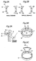
- Fig. 3A shows a state in which the slit 8 out of the four slits 8 to 12 is punched out with a punch 15.
- This punch 15 punches out the slit 8 from radial diagonal inside toward radial diagonal outside.
- This slit 8 is punched out so as to stretch to the part of a window 17, which will be formed in a later process, and an outer annular part 18, which will be cut out in a later process.
- Such a diagonal punch-out process allows the punching distance S (see Fig. 3A) to be reduced as compared with the conventional horizontal punch-out process as shown in Fig. 5B.
- the punching die can be thinned in thickness so that the slit 8 can be reduced in width, thus making it unlikely that another cage catches in the slit, resulting in an improved handleability.
- the cage can be improved in strength and prevented from deformation so that the behavior of sprags to be fitted to the cage can be stabilized and that the performance of the one-way clutch can be improved.
- the case with the slit 8 is the same also with the slits 10, 11 and 12.
- the outer flange 5 is positioned and chucked by making use of the cutouts 6 and 7 serving for chucking positioning, and then a window punch-out process is performed.
- a window punch-out process a plurality of windows 17 are formed in the cylindrical portion 3 of the cylindrical member 2 so as to be spaced circumferentially from one another with specified intervals. Into these windows 17, the sprags of the one-way clutch are fitted, respectively.
- the window punch-out process is done after the formation of the slit 8 as shown above, there occur no burrs at the windows 17 by the slit punch-out process. Therefore, the sprag (not shown) can be smoothly held in the windows 17.
- the outer annular part 18 of the outer flange 5 is punched out as shown in Figs. 1E and 3C.
- This outer annular part 18 ranges from the radially outermost end of the outer flange 5 to a place P that is radially inner than the radially outermost end of the slits 8, 10, 11, 12 by a specified extent.
- the windows 17 communicating with the slits 8, 10 and 11, 12 are opened through to outside of the outer flange 5.
- the cutouts 6, 7 for chucking positioning formed in the slit punch-out process can be utilized in the window punch-out process and the outer ring cutting process, the number of times of positioning can be reduced so that a reduction of manufacturing time as well as a simplification of processes can be achieved.
- pillars 21, 22 beside the window 17 located between the slits 8 and 10 are tilted radially outward so that a rim portion 23 sandwiched by the pair of slits 8 and 10 is protruded radially outward.
- pillars 25, 26 beside another window 17 located between the slits 11 and 12 are tilted radially outward so that a rim portion 27 sandwiched by the pair of slits 11 and 12 is protruded radially outward.
- the rim portions 23, 27 thus protruded radially outward, when the one-way clutch is assembled to an outer ring, presses the inner circumferential surface of the outer ring so that the cage is frictionally coupled to the outer wheel.
- the slits 8, 10, 11, 12 have been punched out radially as shown in Fig. 2A.
Landscapes
- Engineering & Computer Science (AREA)
- General Engineering & Computer Science (AREA)
- Mechanical Engineering (AREA)
- Mechanical Operated Clutches (AREA)
- Punching Or Piercing (AREA)
- Shaping Metal By Deep-Drawing, Or The Like (AREA)
Applications Claiming Priority (2)
| Application Number | Priority Date | Filing Date | Title |
|---|---|---|---|
| JP14559698A JP3746612B2 (ja) | 1998-05-27 | 1998-05-27 | 一方向クラッチの保持器の製造方法 |
| JP14559698 | 1998-05-27 |
Publications (3)
| Publication Number | Publication Date |
|---|---|
| EP0960668A2 true EP0960668A2 (de) | 1999-12-01 |
| EP0960668A3 EP0960668A3 (de) | 2001-09-12 |
| EP0960668B1 EP0960668B1 (de) | 2004-11-10 |
Family
ID=15388732
Family Applications (1)
| Application Number | Title | Priority Date | Filing Date |
|---|---|---|---|
| EP99110252A Expired - Lifetime EP0960668B1 (de) | 1998-05-27 | 1999-05-27 | Verfahren zum Herstellen einer Einwegkupplungsanordnung |
Country Status (4)
| Country | Link |
|---|---|
| US (1) | US6279439B1 (de) |
| EP (1) | EP0960668B1 (de) |
| JP (1) | JP3746612B2 (de) |
| DE (1) | DE69921734T2 (de) |
Cited By (1)
| Publication number | Priority date | Publication date | Assignee | Title |
|---|---|---|---|---|
| EP3037690A1 (de) * | 2014-12-22 | 2016-06-29 | Nsk-Warner K.K. | Einwegkupplung |
Families Citing this family (3)
| Publication number | Priority date | Publication date | Assignee | Title |
|---|---|---|---|---|
| JP3746612B2 (ja) * | 1998-05-27 | 2006-02-15 | 光洋精工株式会社 | 一方向クラッチの保持器の製造方法 |
| US8286353B2 (en) | 2007-07-19 | 2012-10-16 | Nsk-Warner K.K. | Method of manufacturing the outer retainer of a one way clutch that includes windows, by placing the outer retainer into a die and punching out slits in the outer retainer using a thin punch |
| JP5107801B2 (ja) * | 2007-07-19 | 2012-12-26 | Nskワーナー株式会社 | ワンウェイクラッチ用外側保持器の製造方法 |
Family Cites Families (14)
| Publication number | Priority date | Publication date | Assignee | Title |
|---|---|---|---|---|
| US1910285A (en) * | 1932-05-23 | 1933-05-23 | Bohn Aluminium & Brass Corp | Apparatus for forming bearings |
| US2856045A (en) * | 1955-12-27 | 1958-10-14 | Borg Warner | One-way clutches |
| US3005369A (en) * | 1957-11-25 | 1961-10-24 | Vogel Tool & Die Corp | Method of notching and shearing the ends of tubing in the preparation of tubular assemblies |
| US3107566A (en) * | 1960-03-31 | 1963-10-22 | Controls Co Of America | Method of preventing binding of strip material in a progressive type die |
| US3279235A (en) * | 1963-10-07 | 1966-10-18 | United Carr Inc | Method for fabricating a self-retaining protective device |
| US3878705A (en) * | 1972-05-01 | 1975-04-22 | Roger L Iffland | Bearing cage and method for producing a bearing cage |
| JPH01215414A (ja) * | 1988-02-24 | 1989-08-29 | Sanko Kogyo Kk | プレス加工用金型装置 |
| JPH02309021A (ja) * | 1989-05-19 | 1990-12-25 | Ntn Corp | ワンウェイクラッチ・軸受の一体組立構造体 |
| JPH0623579B2 (ja) * | 1989-06-30 | 1994-03-30 | エヌエスケー・ワーナー株式会社 | ワンウエイクラッチ |
| US4998430A (en) * | 1989-09-05 | 1991-03-12 | Emerson Electric Co. | Manufacture of rotor lamination for a dynamoelectric machine |
| JP2965828B2 (ja) * | 1993-08-31 | 1999-10-18 | 光洋精工株式会社 | 一方向クラッチ |
| JP2928078B2 (ja) * | 1994-02-10 | 1999-07-28 | 大日本スクリーン製造株式会社 | 円筒内面走査装置に於ける穿孔装置 |
| US5553525A (en) * | 1994-06-28 | 1996-09-10 | Solar Turbines Incorporated | Punch press machine |
| JP3746612B2 (ja) * | 1998-05-27 | 2006-02-15 | 光洋精工株式会社 | 一方向クラッチの保持器の製造方法 |
-
1998
- 1998-05-27 JP JP14559698A patent/JP3746612B2/ja not_active Expired - Fee Related
-
1999
- 1999-05-26 US US09/318,837 patent/US6279439B1/en not_active Expired - Lifetime
- 1999-05-27 EP EP99110252A patent/EP0960668B1/de not_active Expired - Lifetime
- 1999-05-27 DE DE69921734T patent/DE69921734T2/de not_active Expired - Lifetime
Non-Patent Citations (1)
| Title |
|---|
| None |
Cited By (2)
| Publication number | Priority date | Publication date | Assignee | Title |
|---|---|---|---|---|
| EP3037690A1 (de) * | 2014-12-22 | 2016-06-29 | Nsk-Warner K.K. | Einwegkupplung |
| US10422392B2 (en) | 2014-12-22 | 2019-09-24 | Nsk-Warner K.K. | Unidirectional clutch |
Also Published As
| Publication number | Publication date |
|---|---|
| JPH11336798A (ja) | 1999-12-07 |
| EP0960668B1 (de) | 2004-11-10 |
| DE69921734T2 (de) | 2005-11-03 |
| DE69921734D1 (de) | 2004-12-16 |
| EP0960668A3 (de) | 2001-09-12 |
| JP3746612B2 (ja) | 2006-02-15 |
| US6279439B1 (en) | 2001-08-28 |
Similar Documents
| Publication | Publication Date | Title |
|---|---|---|
| US4874073A (en) | Clutch release bearing device | |
| CN111734743A (zh) | 轴承保持架 | |
| US20080135369A1 (en) | Stamped clutch pocket plate, method for making the pocket plate, and clutch including the pocket plate | |
| JP2003507661A (ja) | ワンウエイクラッチ及びその製造方法 | |
| KR100914902B1 (ko) | 단방향 클러치 제조방법 | |
| EP2749779B1 (de) | Montageverfahren für Lagereinheit | |
| EP2103825A1 (de) | Halter für ein druckrollenlager und druckrollenlager | |
| US5391005A (en) | Bearing cage with depressed slot end | |
| US5906135A (en) | Coast clutch with power take off gear | |
| EP0473143B1 (de) | Kombiniertes Axial-Radiallager | |
| WO1998041775A1 (en) | Clutch drum and method of manufacture | |
| JP2003083339A (ja) | スラスト軸受 | |
| EP1830083B1 (de) | Axialwälzlager | |
| EP0960668B1 (de) | Verfahren zum Herstellen einer Einwegkupplungsanordnung | |
| US4985973A (en) | Manufacturing method for diaphragm spring | |
| US20040035668A1 (en) | Assembly for vehicle driveline components | |
| US7243770B2 (en) | Clutch assembly including strengthening members | |
| WO2016031644A1 (ja) | 軸受装置及び軸受装置の製造方法 | |
| US20060137955A1 (en) | One-way clutch | |
| CN118934846A (zh) | 用于分段式保持架的保持架段 | |
| WO2015066293A1 (en) | Forming a drawn cup with undercuts | |
| JP7469639B2 (ja) | 自動調心ころ軸受用保持器の製造方法 | |
| US4502740A (en) | Method of making a retainer for solid type roller bearing | |
| JPH0594527U (ja) | スラストニードル軸受 | |
| JP2003287041A (ja) | シールド板および転がり軸受 |
Legal Events
| Date | Code | Title | Description |
|---|---|---|---|
| PUAI | Public reference made under article 153(3) epc to a published international application that has entered the european phase |
Free format text: ORIGINAL CODE: 0009012 |
|
| AK | Designated contracting states |
Kind code of ref document: A2 Designated state(s): AT BE CH CY DE DK ES FI FR GB GR IE IT LI LU MC NL PT SE Kind code of ref document: A2 Designated state(s): DE FR |
|
| AX | Request for extension of the european patent |
Free format text: AL;LT;LV;MK;RO;SI |
|
| PUAL | Search report despatched |
Free format text: ORIGINAL CODE: 0009013 |
|
| AK | Designated contracting states |
Kind code of ref document: A3 Designated state(s): AT BE CH CY DE DK ES FI FR GB GR IE IT LI LU MC NL PT SE |
|
| AX | Request for extension of the european patent |
Free format text: AL;LT;LV;MK;RO;SI |
|
| RIC1 | Information provided on ipc code assigned before grant |
Free format text: 7B 21D 53/12 A, 7B 21D 53/26 B, 7F 16D 41/07 B |
|
| 17P | Request for examination filed |
Effective date: 20011130 |
|
| AKX | Designation fees paid |
Free format text: DE FR |
|
| 17Q | First examination report despatched |
Effective date: 20020711 |
|
| GRAP | Despatch of communication of intention to grant a patent |
Free format text: ORIGINAL CODE: EPIDOSNIGR1 |
|
| GRAS | Grant fee paid |
Free format text: ORIGINAL CODE: EPIDOSNIGR3 |
|
| GRAA | (expected) grant |
Free format text: ORIGINAL CODE: 0009210 |
|
| AK | Designated contracting states |
Kind code of ref document: B1 Designated state(s): DE FR |
|
| REF | Corresponds to: |
Ref document number: 69921734 Country of ref document: DE Date of ref document: 20041216 Kind code of ref document: P |
|
| PLBE | No opposition filed within time limit |
Free format text: ORIGINAL CODE: 0009261 |
|
| STAA | Information on the status of an ep patent application or granted ep patent |
Free format text: STATUS: NO OPPOSITION FILED WITHIN TIME LIMIT |
|
| ET | Fr: translation filed | ||
| 26N | No opposition filed |
Effective date: 20050811 |
|
| REG | Reference to a national code |
Ref country code: FR Ref legal event code: PLFP Year of fee payment: 18 |
|
| PGFP | Annual fee paid to national office [announced via postgrant information from national office to epo] |
Ref country code: DE Payment date: 20160524 Year of fee payment: 18 |
|
| REG | Reference to a national code |
Ref country code: FR Ref legal event code: PLFP Year of fee payment: 19 |
|
| PGFP | Annual fee paid to national office [announced via postgrant information from national office to epo] |
Ref country code: FR Payment date: 20170413 Year of fee payment: 19 |
|
| REG | Reference to a national code |
Ref country code: DE Ref legal event code: R119 Ref document number: 69921734 Country of ref document: DE |
|
| PG25 | Lapsed in a contracting state [announced via postgrant information from national office to epo] |
Ref country code: DE Free format text: LAPSE BECAUSE OF NON-PAYMENT OF DUE FEES Effective date: 20171201 |
|
| PG25 | Lapsed in a contracting state [announced via postgrant information from national office to epo] |
Ref country code: FR Free format text: LAPSE BECAUSE OF NON-PAYMENT OF DUE FEES Effective date: 20180531 |