US5391005A - Bearing cage with depressed slot end - Google Patents

Bearing cage with depressed slot end Download PDF

Info

Publication number
US5391005A
US5391005A US08/040,399 US4039993A US5391005A US 5391005 A US5391005 A US 5391005A US 4039993 A US4039993 A US 4039993A US 5391005 A US5391005 A US 5391005A
Authority
US
United States
Prior art keywords
roller
bearing cage
roller bearing
crossbars
portions
Prior art date
Legal status (The legal status is an assumption and is not a legal conclusion. Google has not performed a legal analysis and makes no representation as to the accuracy of the status listed.)
Expired - Fee Related
Application number
US08/040,399
Inventor
Richard L. Alling
Current Assignee (The listed assignees may be inaccurate. Google has not performed a legal analysis and makes no representation or warranty as to the accuracy of the list.)
Torrington Co Ltd
Timken US LLC
Original Assignee
Torrington Co
Priority date (The priority date is an assumption and is not a legal conclusion. Google has not performed a legal analysis and makes no representation as to the accuracy of the date listed.)
Filing date
Publication date
Application filed by Torrington Co filed Critical Torrington Co
Priority to US08/040,399 priority Critical patent/US5391005A/en
Assigned to TORRINGTON COMPANY, THE reassignment TORRINGTON COMPANY, THE ASSIGNMENT OF ASSIGNORS INTEREST. Assignors: ALLING, RICHARD L.
Priority to US08/196,002 priority patent/US5410809A/en
Priority to DE69528149T priority patent/DE69528149T2/en
Priority to ES95300851T priority patent/ES2182866T3/en
Priority to EP95300851A priority patent/EP0726404B1/en
Application granted granted Critical
Publication of US5391005A publication Critical patent/US5391005A/en
Anticipated expiration legal-status Critical
Expired - Fee Related legal-status Critical Current

Links

Images

Classifications

    • FMECHANICAL ENGINEERING; LIGHTING; HEATING; WEAPONS; BLASTING
    • F16ENGINEERING ELEMENTS AND UNITS; GENERAL MEASURES FOR PRODUCING AND MAINTAINING EFFECTIVE FUNCTIONING OF MACHINES OR INSTALLATIONS; THERMAL INSULATION IN GENERAL
    • F16CSHAFTS; FLEXIBLE SHAFTS; ELEMENTS OR CRANKSHAFT MECHANISMS; ROTARY BODIES OTHER THAN GEARING ELEMENTS; BEARINGS
    • F16C33/00Parts of bearings; Special methods for making bearings or parts thereof
    • F16C33/30Parts of ball or roller bearings
    • F16C33/46Cages for rollers or needles
    • F16C33/54Cages for rollers or needles made from wire, strips, or sheet metal
    • F16C33/542Cages for rollers or needles made from wire, strips, or sheet metal made from sheet metal
    • F16C33/543Cages for rollers or needles made from wire, strips, or sheet metal made from sheet metal from a single part
    • F16C33/546Cages for rollers or needles made from wire, strips, or sheet metal made from sheet metal from a single part with a M- or W-shaped cross section
    • FMECHANICAL ENGINEERING; LIGHTING; HEATING; WEAPONS; BLASTING
    • F16ENGINEERING ELEMENTS AND UNITS; GENERAL MEASURES FOR PRODUCING AND MAINTAINING EFFECTIVE FUNCTIONING OF MACHINES OR INSTALLATIONS; THERMAL INSULATION IN GENERAL
    • F16CSHAFTS; FLEXIBLE SHAFTS; ELEMENTS OR CRANKSHAFT MECHANISMS; ROTARY BODIES OTHER THAN GEARING ELEMENTS; BEARINGS
    • F16C19/00Bearings with rolling contact, for exclusively rotary movement
    • F16C19/22Bearings with rolling contact, for exclusively rotary movement with bearing rollers essentially of the same size in one or more circular rows, e.g. needle bearings
    • F16C19/44Needle bearings
    • F16C19/48Needle bearings with two or more rows of needles
    • FMECHANICAL ENGINEERING; LIGHTING; HEATING; WEAPONS; BLASTING
    • F16ENGINEERING ELEMENTS AND UNITS; GENERAL MEASURES FOR PRODUCING AND MAINTAINING EFFECTIVE FUNCTIONING OF MACHINES OR INSTALLATIONS; THERMAL INSULATION IN GENERAL
    • F16CSHAFTS; FLEXIBLE SHAFTS; ELEMENTS OR CRANKSHAFT MECHANISMS; ROTARY BODIES OTHER THAN GEARING ELEMENTS; BEARINGS
    • F16C19/00Bearings with rolling contact, for exclusively rotary movement
    • F16C19/22Bearings with rolling contact, for exclusively rotary movement with bearing rollers essentially of the same size in one or more circular rows, e.g. needle bearings
    • F16C19/44Needle bearings
    • F16C19/46Needle bearings with one row or needles
    • F16C19/463Needle bearings with one row or needles consisting of needle rollers held in a cage, i.e. subunit without race rings
    • FMECHANICAL ENGINEERING; LIGHTING; HEATING; WEAPONS; BLASTING
    • F16ENGINEERING ELEMENTS AND UNITS; GENERAL MEASURES FOR PRODUCING AND MAINTAINING EFFECTIVE FUNCTIONING OF MACHINES OR INSTALLATIONS; THERMAL INSULATION IN GENERAL
    • F16CSHAFTS; FLEXIBLE SHAFTS; ELEMENTS OR CRANKSHAFT MECHANISMS; ROTARY BODIES OTHER THAN GEARING ELEMENTS; BEARINGS
    • F16C2300/00Application independent of particular apparatuses
    • F16C2300/02General use or purpose, i.e. no use, purpose, special adaptation or modification indicated or a wide variety of uses mentioned

Abstract

A flat strip of metal is formed to provide a depressed center relief portion between two edge portions. Depressions are formed in the two edge portions and center slots are pierced across the center relief portion such that roller receiving slots are formed with slot end depressions at both ends of the roller receiving slots. The partially formed bearing cage is then formed into a circular hoop such that the edge portions form rings at the axial ends of the circular hoop. The resulting roller bearing cage of the present invention may also be formed by other methods.

Description

BACKGROUND OF THE INVENTION
This invention relates generally to roller bearing cages and, more particularly, to roller bearing cages of "sigma" configuration.
Roller bearings commonly employ separators, retainers or cages to maintain separation and alignment of the rollers. Although the terms are frequently used interchangeably, the term "cage" is often used to describe a device that retains the rollers both radially and axially. Thus, a roller bearing cage prevents rollers from moving axially or radially out of the cage, allowing the cage and rollers to be handled as a bearing subassembly.
One particular type of roller bearing cage is known as a sigma cage. As illustrated in FIG. 1, a typical sigma cage 10 has annular end rims 12 and 14, axially spaced apart along a common axis, joined together by crossbars 16 to form slots 18 for receiving rollers, not shown. Crossbars 16 have a central portion 20 offset radially inwardly from laterally outward portions 22 and 24 such that, when viewed in longitudinal section, end rims 12 and 14 and crossbars 16 resemble the Greek letter "sigma".
End rims 12 and 14 extend radially as end flanges 26 and 28, respectively. End flanges 26 and 28 provide stop surfaces which assist slots 18 to ensure that axial movement of the rollers is restricted. Edge surfaces on central portion 20 prevent radially inward movement of the rollers and edge surfaces of laterally outward portions 22 and 24 prevent radially outward movement of the rollers.
In some applications, a significant axial offset is required between the roller pockets (slots) and the end flanges of the cage. Such offset materially affects the axial containment of the rollers because the end flanges no longer provide stop surfaces proximate to the slots. As a result, roller loss can occur during handling of the cage before installation or upon installation of the bearing in the housing.
The foregoing illustrates limitations known to exist in present roller bearing cages of sigma configuration. Thus, it is apparent that it would be advantageous to provide an alternative directed to overcoming one or more of the limitations set forth above. Accordingly, a suitable alternative is provided including features more fully disclosed hereinafter.
SUMMARY OF THE INVENTION
In one aspect of the present invention, this is accomplished by providing a method for forming a roller bearing cage with depressed slot ends. A flat strip of metal is formed to provide a depressed center relief portion between two edge portions. Depressions are formed in the two edge portions and center slots are pierced across the center relief portion such that roller receiving slots are formed with slot end depressions at both ends of the roller receiving slots. The partially formed bearing cage is then formed into a circular hoop such that the edge portions form rings at the axial ends of the circular hoop.
In another aspect of the present invention, a roller bearing cage is provided having axially spaced end rims. Crossbars join the end rims such that roller receiving slots are formed, the crossbars having a central portion radially offset with respect to laterally outward portions such that a roller is retained in the radial directions. Radially offset rim portions are located between the crossbars such that a roller within one of the roller receiving slots is retained in each axial direction by engagement with one radially offset rim portion at each end of the roller receiving slot.
The foregoing and other aspects will become apparent from the following detailed description of the invention when considered in conjunction with the accompanying drawing figures.
BRIEF DESCRIPTION OF THE DRAWING FIGURES
FIG. 1 is an isometric view illustrating a prior art roller bearing sigma cage;
FIG. 2 is an isometric view illustrating an embodiment of the roller bearing cage of the present invention;
FIG. 3 is a sectional view of two roller bearing cages of FIG. 2 as installed in an elongated bearing housing having a cross drilled lubrication hole; and
FIG. 4 is a diagram illustrating outlines of multiple punches that may be used to pierce slots of the bearing cage of FIG. 2; and
FIG. 5 is a sectional view of a roller bearing cage illustrating a second embodiment of the present invention.
DETAILED DESCRIPTION
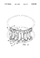
Referring now to the drawings, FIG. 2 illustrates a preferred embodiment of roller bearing cage 30 of the present invention having annular end rims 32 and 34, axially spaced apart along a common axis, joined together by crossbars 36 to form slots 38 for receiving rollers, not shown. Crossbars 36 have a central portion 40 offset radially inwardly from laterally outward portions 42 and 44. Cage 30 is considered a sigma cage because end rims 32 and 34 and crossbars 36 suggest the Greek letter "sigma" when the cage is viewed in longitudinal section.
Unlike the roller bearing cage of FIG. 1, roller bearing cage 30 has depressed slot ends designed to abut end surfaces of bearing rollers received within slots 38. Abutment surfaces 46 are formed by periodic depressions 48, one at each end of roller receiving slots 38, to prevent escape of the bearing rollers, especially in the absence of close proximity bearing cage flanges. Specifically, axial movement of the bearing rollers in both axial directions is limited by engagement of abutment surfaces 46 by the bearing rollers.
In the particular embodiment shown, abutment surfaces 46 have a curved profile, curved with a circular arc or otherwise, along a transverse section of bearing cage 30. Depressions 48 are dimple-like recesses having a substantially angular longitudinal section and a substantially conical configuration. However, depressions 48 may be of various shape, depending on the shape of tooling used to form the recesses, as described below.
End rims 32 and 34 comprise axially extending portions side 50 and flange portions 52 extending radially inwardly at the axially outward ends of axially extending side portions 50. Depressions 48 are formed within axially extending side portions 50 at locations between crossbars 36. Abutment surfaces 46 are radially offset rim portions forming ends of slots 38. End rims 32 and 34 and crossbars 36 are formed from a single sheet of steel or other metal and have substantially the same thickness.
As illustrated in FIG. 2, central portions 40 of crossbars 36 and abutment surfaces 46 are offset radially inwardly relative to laterally outward portions 42 and 44 of crossbars 36. However, the present invention is not limited to that configuration and may also be utilized to provide an inverted sigma bearing cage, illustrated in FIG. 5, in which central portions 76 and abutment portions 78 are offset radially outwardly. Similarly, flange portions 80 may extend radially outwardly rather than radially inwardly or may be omitted.
FIG. 3 illustrates an example requiring a significant offset of the roller receiving slots from the bearing flanges. Two roller bearing cages 30, shown in longitudinal section, are installed in an elongated bearing housing 54 having a cross drilled lubrication hole 56. Depressions 48 of end rims 32 and 34 allow two roller cage bearings to maintain proper axial location of rollers 58 and 60 without roller interference to the breakout location of lubrication hole 56 on load bearing shaft 62.
End washers 64 and 66 mounted on bearing housing 54 engage outward flanges of roller bearing cages 30 to limit outward axial movement of the cages. Inward flanges of roller bearing cages 30 overlie lubrication hole 56 and abut each other to limit inward axial movement of the cages. Central portions 40 of crossbars 36 separate rollers 58 and 60 circumferentially and cooperate with outward portions 42 (FIG. 2) to contain the rollers during handling and installation.
The preferred method of manufacturing roller bearing cage 30 is by flat blank, wrap, and weld, using multislide techniques. Flat coil stock of uniform section is pressed to form a depressed center relief portion between two edge portions. Pairs of slot end relief openings are pierced in the edge portions, and forming punches are seated against the laterally outward edges of the slot end relief openings, thereby forming angled slot end depressions 48.
Center slots are then pierced across the center relief portion and between each pair of slot end relief openings to provide the remaining perimeter of slots 38 such that depressions 48 are at the ends of slots 38. Strip edge gutting and flange forming may be used to trim and shape edges of the resulting cage blank. The cage blank is cut to a predetermined length by a block cut from the formed strip. The completed blank is wrapped to a 360 degree circular hoop and welded such that the edge portions form rings at the axial ends of the resulting cage.
FIG. 4 illustrates outlines and relative positions of multiple punches that may be used to pierce slots 38 according to the method just described. Heavier outlines 68 and 70 represent the shape of one pair of slot end relief openings pierced in the edge portions of the flat strip. Light outline 72 represents the shape of tooling used to pierce the center slots across the slot end relief openings.
As shown by the positions illustrated, the opening pierced by the center slot punch blends with the slot end relief openings, even if a slight misalignment of the punches occurs. The separate cutting of the slot end relief openings avoids distortion to the slot that might occur during pressing to form depressions 48. Overlapping of the punches results in circumferentially extending trapezoidal shaped tabs 74 (also in FIG. 2) which extend into the roller receiving slots and assist in controlling radially outward movement of the rollers.
Alternatively, depressions 48 may be formed by pressing a "dimple" or recess in the edge portions of the metal strip without piercing of slot end relief openings. The full perimeter of slots 38 would then be pierced such that a portion of the dimple remains, thereby providing depressions 48. That method ensures a square profile (in longitudinal section) abutment surface 46 which gives maximum contact with the ends of the rollers; however, tool maintenance with that alternative method may be more difficult.
Other variations in the method of manufacturing cage 30 or the inverted sigma bearing cage are included in the present invention. Depressions 48 may be formed either before or after piercing of the center slots. Depressions 48 and slots 38 may also be formed and pierced simultaneously or may be accomplished by a single tool. Strip edge gutting, flanging and welding steps may be added or omitted, as desired. Joining ends of the circular hoop may be by other means than welding or may be omitted.
From the above description, it will be apparent that the present invention provides a solution to the end containment problem in conventional sigma bearing cages which results in roller loss during handling and upon bearing installation, especially when a significant offset is required between the rollers and the end flanges. Axial emergence of the bearing rollers is prevented by roller contact with the depressed slot end to maintain proper location of the rollers.

Claims (8)

Having described the invention, what is claimed is:
1. A roller bearing cage comprising:
first and second end rims axially spaced apart with respect to a common axis, each of the end rims having an axially outward end, an axially extending side portion, and a plurality of periodic depressions axially spaced from the outward ends; and
crossbars joining the first and second end rims such that roller receiving slots are formed therebetween, the crossbars having laterally outward portions and a central portion radially offset with respect to the laterally outward portions;
the crossbars being configured such that a roller within one of the roller receiving slots is retained in the radial directions by engagement with the central portion and with the laterally outward portions;
the periodic depressions being located between the crossbars, one at each end of the roller receiving slots, such that a roller within one of the roller receiving slots is retained in the axial directions by engagement with the periodic depressions at each end of the roller receiving slot.
2. The roller bearing cage according to claim 1, wherein the end rims and crossbars are formed from a single sheet of metal and have substantially the same thickness.
3. The roller bearing cage according to claim 1, wherein the periodic depressions include surfaces having an angled profile in longitudinal section.
4. The roller bearing cage according to claim 1, wherein the periodic depressions include roller engaging abutment surfaces having a curved profile in transverse section.
5. The roller bearing cage according to claim 1, wherein the central portion and the periodic depressions are both offset radially inwardly with respect to the side portions.
6. The roller bearing cage according to claim 1, wherein the central portion and the periodic depressions are both offset radially outwardly with respect to the side portions.
7. The roller bearing cage according to claim 1, wherein the laterally outward portions of the crossbars include at least one tab extending circumferentially into the roller receiving slots.
8. The roller bearing cage according to claim 1, wherein each end rim includes a radially extending flange portion at the axially outward ends of the axially extending side portions of the end rims.
US08/040,399 1993-03-30 1993-03-30 Bearing cage with depressed slot end Expired - Fee Related US5391005A (en)

Priority Applications (5)

Application Number Priority Date Filing Date Title
US08/040,399 US5391005A (en) 1993-03-30 1993-03-30 Bearing cage with depressed slot end
US08/196,002 US5410809A (en) 1993-03-30 1994-02-10 Method of making a bearing cage with depressed slot end
DE69528149T DE69528149T2 (en) 1993-03-30 1995-02-10 Roller bearing cage and its manufacturing method
ES95300851T ES2182866T3 (en) 1993-03-30 1995-02-10 CAGE FOR ROLLER BEARING AND METHOD TO FORM IT.
EP95300851A EP0726404B1 (en) 1993-03-30 1995-02-10 Roller bearing cage and method of forming same

Applications Claiming Priority (2)

Application Number Priority Date Filing Date Title
US08/040,399 US5391005A (en) 1993-03-30 1993-03-30 Bearing cage with depressed slot end
EP95300851A EP0726404B1 (en) 1993-03-30 1995-02-10 Roller bearing cage and method of forming same

Related Child Applications (1)

Application Number Title Priority Date Filing Date
US08/196,002 Division US5410809A (en) 1993-03-30 1994-02-10 Method of making a bearing cage with depressed slot end

Publications (1)

Publication Number Publication Date
US5391005A true US5391005A (en) 1995-02-21

Family

ID=26140026

Family Applications (1)

Application Number Title Priority Date Filing Date
US08/040,399 Expired - Fee Related US5391005A (en) 1993-03-30 1993-03-30 Bearing cage with depressed slot end

Country Status (4)

Country Link
US (1) US5391005A (en)
EP (1) EP0726404B1 (en)
DE (1) DE69528149T2 (en)
ES (1) ES2182866T3 (en)

Cited By (18)

* Cited by examiner, † Cited by third party
Publication number Priority date Publication date Assignee Title
DE19635137A1 (en) * 1996-08-30 1998-03-05 Schaeffler Waelzlager Kg Roller-bearing cage
US5816713A (en) * 1996-09-03 1998-10-06 The Torrington Company Bearing cage with T-shaped pitoling pads
DE19812252A1 (en) * 1998-03-20 1999-09-23 Schaeffler Waelzlager Ohg Needle roller bearing cage with slit in shoulder between two crosspieces
US6068406A (en) * 1997-08-06 2000-05-30 Ntn Corporation Needle roller bearing
US6238098B1 (en) * 1998-12-29 2001-05-29 The Torrington Company Roller bearing cage
US20050094913A1 (en) * 2003-11-03 2005-05-05 Timken Us Corporation Unitized bearing assembly
DE102004031027A1 (en) * 2004-06-26 2006-01-12 Ina-Schaeffler Kg Needle cage for e.g. radial bearing, has guide arranged at front faces of slot and forming stop face for rolling body in radially bent state, where guide has exemptions arranged within area of sections in circumferential directions
US20070068338A1 (en) * 2005-07-04 2007-03-29 Kenichi Ichikawa Needle roller bearing and its manufacturing method
JP2008175310A (en) * 2007-01-19 2008-07-31 Jtekt Corp Thrust roller bearing cage and thrust roller bearing
US20100322549A1 (en) * 2009-06-15 2010-12-23 Koyo Bearings Usa Llc Cage for bearing assembly
US20110142389A1 (en) * 2008-07-08 2011-06-16 Nsk Ltd. Tapered roller bearing resin cage and tapered roller bearing
US20120263405A1 (en) * 2009-11-17 2012-10-18 Nsk Ltd. Tapered Roller Bearing and Manufacturing Method for Retainer of Tapered Roller Bearing
US8702315B2 (en) 2011-11-03 2014-04-22 Schaeffler Technologies AG & Co. KG Radial cage for cylindrical roller bodies
US8714833B2 (en) * 2011-11-03 2014-05-06 Schaeffler Technologies AG & Co. KG Radial cage for cylindrical roller bodies
US8926191B2 (en) 2010-05-03 2015-01-06 Schaeffler Technologies AG & Co. KG Axial cage for cylindrical rolling elements
US20160363166A1 (en) * 2015-06-09 2016-12-15 Aktiebolaget Skf Radial cage for bearings having high rotational speeds
CN110778693A (en) * 2018-07-26 2020-02-11 赛峰传动系统公司 Device of the reduction gear type or of the differential type for a turbine engine of an aircraft
CN111288075A (en) * 2018-12-10 2020-06-16 斯凯孚公司 Roller bearing

Families Citing this family (1)

* Cited by examiner, † Cited by third party
Publication number Priority date Publication date Assignee Title
DE19702192A1 (en) * 1997-01-23 1998-07-30 Schaeffler Waelzlager Ohg Needle cage for roller body

Citations (12)

* Cited by examiner, † Cited by third party
Publication number Priority date Publication date Assignee Title
US1232523A (en) * 1917-05-15 1917-07-10 Edward S Folk Roller-bearing.
US1870892A (en) * 1930-04-23 1932-08-09 Charles S Brown Roller bearing construction
US1951042A (en) * 1927-11-19 1934-03-13 Firm Pfingstmann Werke Ag Roller bearing cage
DE851283C (en) * 1940-09-24 1952-10-02 Ver Kugellagerfabriken Ag One-piece sheet metal cage for roller bearings
US3042464A (en) * 1960-01-12 1962-07-03 Skf Svenska Kullagerfab Ab Roller cage for cylindrical roller bearings
US3307892A (en) * 1963-08-13 1967-03-07 Schaeffler Ohg Industriewerk Cage for cylindrical rollers
US3365775A (en) * 1967-04-21 1968-01-30 Torrington Mfg Co Method of making bearing separators and the like
US3442562A (en) * 1966-02-17 1969-05-06 Schaeffler Ohg Industriewerk Cage for cylindrical rollers
GB1388645A (en) * 1972-04-26 1975-03-26 Skf Ind Trading & Dev Unitary cage for roller bearings having an inner race ring formed with lateral flanges and a removable outer race ring and method of shaping the cage on assembly of the bearing
SU684192A1 (en) * 1978-03-15 1979-09-05 Livshits Boris A Roller bearing cage
US4192560A (en) * 1978-08-21 1980-03-11 The Torrington Company Bearing with bearing cage
US4710039A (en) * 1986-03-12 1987-12-01 Skf Gmbh Cage for roller bearing

Family Cites Families (5)

* Cited by examiner, † Cited by third party
Publication number Priority date Publication date Assignee Title
US1871149A (en) * 1930-04-23 1932-08-09 Charles S Brown Roller bearing construction
GB911447A (en) * 1959-12-16 1962-11-28 Skf Svenska Kullagerfab Ab Improvements in or relating to roller cages for cylindrical roller bearings
DE1811634U (en) * 1960-01-19 1960-05-19 Kugelfischer G Schaefer & Co ROLLER BEARINGS, IN PARTICULAR CYLINDER ROLLER BEARINGS.
FR1414486A (en) * 1964-11-20 1965-10-15 Duerkoppwerke Ag Sheet metal cage for needle roller bearings and its manufacturing process
US5255985A (en) * 1992-11-17 1993-10-26 The Torrington Company Roller bearing sigma cage

Patent Citations (12)

* Cited by examiner, † Cited by third party
Publication number Priority date Publication date Assignee Title
US1232523A (en) * 1917-05-15 1917-07-10 Edward S Folk Roller-bearing.
US1951042A (en) * 1927-11-19 1934-03-13 Firm Pfingstmann Werke Ag Roller bearing cage
US1870892A (en) * 1930-04-23 1932-08-09 Charles S Brown Roller bearing construction
DE851283C (en) * 1940-09-24 1952-10-02 Ver Kugellagerfabriken Ag One-piece sheet metal cage for roller bearings
US3042464A (en) * 1960-01-12 1962-07-03 Skf Svenska Kullagerfab Ab Roller cage for cylindrical roller bearings
US3307892A (en) * 1963-08-13 1967-03-07 Schaeffler Ohg Industriewerk Cage for cylindrical rollers
US3442562A (en) * 1966-02-17 1969-05-06 Schaeffler Ohg Industriewerk Cage for cylindrical rollers
US3365775A (en) * 1967-04-21 1968-01-30 Torrington Mfg Co Method of making bearing separators and the like
GB1388645A (en) * 1972-04-26 1975-03-26 Skf Ind Trading & Dev Unitary cage for roller bearings having an inner race ring formed with lateral flanges and a removable outer race ring and method of shaping the cage on assembly of the bearing
SU684192A1 (en) * 1978-03-15 1979-09-05 Livshits Boris A Roller bearing cage
US4192560A (en) * 1978-08-21 1980-03-11 The Torrington Company Bearing with bearing cage
US4710039A (en) * 1986-03-12 1987-12-01 Skf Gmbh Cage for roller bearing

Cited By (30)

* Cited by examiner, † Cited by third party
Publication number Priority date Publication date Assignee Title
DE19635137A1 (en) * 1996-08-30 1998-03-05 Schaeffler Waelzlager Kg Roller-bearing cage
US5816713A (en) * 1996-09-03 1998-10-06 The Torrington Company Bearing cage with T-shaped pitoling pads
US6068406A (en) * 1997-08-06 2000-05-30 Ntn Corporation Needle roller bearing
DE19812252A1 (en) * 1998-03-20 1999-09-23 Schaeffler Waelzlager Ohg Needle roller bearing cage with slit in shoulder between two crosspieces
US6206576B1 (en) 1998-03-20 2001-03-27 Ina Walzlanger Schaeffler Ohg Cage for cylindrical rolling elements
US6238098B1 (en) * 1998-12-29 2001-05-29 The Torrington Company Roller bearing cage
US20050094913A1 (en) * 2003-11-03 2005-05-05 Timken Us Corporation Unitized bearing assembly
US6969202B2 (en) 2003-11-03 2005-11-29 Timken Us Corporation Unitized bearing assembly
DE102004031027A1 (en) * 2004-06-26 2006-01-12 Ina-Schaeffler Kg Needle cage for e.g. radial bearing, has guide arranged at front faces of slot and forming stop face for rolling body in radially bent state, where guide has exemptions arranged within area of sections in circumferential directions
US7571706B2 (en) * 2005-07-04 2009-08-11 Ntn Corporation Needle roller bearing and its manufacturing method
US20070068338A1 (en) * 2005-07-04 2007-03-29 Kenichi Ichikawa Needle roller bearing and its manufacturing method
EP2103825A4 (en) * 2007-01-19 2011-01-19 Jtekt Corp Retainer for thrust roller bearing and thrust roller bearing
EP2103825A1 (en) * 2007-01-19 2009-09-23 JTEKT Corporation Retainer for thrust roller bearing and thrust roller bearing
JP2008175310A (en) * 2007-01-19 2008-07-31 Jtekt Corp Thrust roller bearing cage and thrust roller bearing
US20110142389A1 (en) * 2008-07-08 2011-06-16 Nsk Ltd. Tapered roller bearing resin cage and tapered roller bearing
US9039288B2 (en) * 2008-07-08 2015-05-26 Nsk Ltd. Tapered roller bearing resin cage and tapered roller bearing
US20100322549A1 (en) * 2009-06-15 2010-12-23 Koyo Bearings Usa Llc Cage for bearing assembly
US8602657B2 (en) * 2009-06-15 2013-12-10 Koyo Bearings Usa Llc Cage for bearing assembly
US20120263405A1 (en) * 2009-11-17 2012-10-18 Nsk Ltd. Tapered Roller Bearing and Manufacturing Method for Retainer of Tapered Roller Bearing
US8998498B2 (en) * 2009-11-17 2015-04-07 Nsk Ltd. Tapered roller bearing and manufacturing method for retainer of tapered roller bearing
US8926191B2 (en) 2010-05-03 2015-01-06 Schaeffler Technologies AG & Co. KG Axial cage for cylindrical rolling elements
US8714833B2 (en) * 2011-11-03 2014-05-06 Schaeffler Technologies AG & Co. KG Radial cage for cylindrical roller bodies
US8702315B2 (en) 2011-11-03 2014-04-22 Schaeffler Technologies AG & Co. KG Radial cage for cylindrical roller bodies
US20160363166A1 (en) * 2015-06-09 2016-12-15 Aktiebolaget Skf Radial cage for bearings having high rotational speeds
US9856915B2 (en) * 2015-06-09 2018-01-02 Aktiebolaget Skf Radial cage for bearings having high rotational speeds
CN110778693A (en) * 2018-07-26 2020-02-11 赛峰传动系统公司 Device of the reduction gear type or of the differential type for a turbine engine of an aircraft
US11131249B2 (en) * 2018-07-26 2021-09-28 Safran Transmission Systems Reduction or differential-type device for a turbine engine of an aircraft
CN110778693B (en) * 2018-07-26 2023-11-21 赛峰传动系统公司 Device of the reduction gear type or of the differential type for a turbine engine of an aircraft
CN111288075A (en) * 2018-12-10 2020-06-16 斯凯孚公司 Roller bearing
CN111288075B (en) * 2018-12-10 2023-07-04 斯凯孚公司 Roller bearing

Also Published As

Publication number Publication date
EP0726404B1 (en) 2002-09-11
EP0726404A1 (en) 1996-08-14
ES2182866T3 (en) 2003-03-16
DE69528149D1 (en) 2002-10-17
DE69528149T2 (en) 2003-04-30

Similar Documents

Publication Publication Date Title
US5391005A (en) Bearing cage with depressed slot end
US5255985A (en) Roller bearing sigma cage
US5528706A (en) Cage for roller bearings
US5896970A (en) Clutch housing
US5410809A (en) Method of making a bearing cage with depressed slot end
US5972476A (en) Laminated parts and method of making same
US6223574B1 (en) Thin-walled ring-shaped member and method of manufacturing same
US4505608A (en) Lightened yoke for a universal joint
EP0013628A1 (en) Roller bearing
CN107178562B (en) Clutch ring gear assembly and method of construction thereof
US4138776A (en) Method for fabricating pulleys
JP4811056B2 (en) Method for manufacturing roller bearing and tapered roller bearing
JPH06280864A (en) Needle roller bearing
EP0867630B1 (en) Method of manufacturing a rotor for an electromagnetic clutch assembly
US20220003271A1 (en) Sheet metal panel raceway including recesses
US4587833A (en) Staking system
US3961406A (en) Method of pulley construction
JP2005195143A (en) Needle roller bearing
JP2010014222A (en) Method for working outer race of one-way clutch of roller type
US4236289A (en) Apparatus and method for fabricating pulleys
JPH06249246A (en) Cage for roller bearing
US6279439B1 (en) Method for manufacturing a one-way clutch cage
US4502740A (en) Method of making a retainer for solid type roller bearing
US11603885B2 (en) Raceway element and method for its manufacture
US20240077111A1 (en) Cage segment for a segmented cage

Legal Events

Date Code Title Description
AS Assignment

Owner name: TORRINGTON COMPANY, THE, CONNECTICUT

Free format text: ASSIGNMENT OF ASSIGNORS INTEREST.;ASSIGNOR:ALLING, RICHARD L.;REEL/FRAME:006503/0983

Effective date: 19930329

FEPP Fee payment procedure

Free format text: PAYOR NUMBER ASSIGNED (ORIGINAL EVENT CODE: ASPN); ENTITY STATUS OF PATENT OWNER: LARGE ENTITY

FPAY Fee payment

Year of fee payment: 4

FPAY Fee payment

Year of fee payment: 8

REMI Maintenance fee reminder mailed
LAPS Lapse for failure to pay maintenance fees
STCH Information on status: patent discontinuation

Free format text: PATENT EXPIRED DUE TO NONPAYMENT OF MAINTENANCE FEES UNDER 37 CFR 1.362

FP Lapsed due to failure to pay maintenance fee

Effective date: 20070221