EP0959397B1 - Verpackungsmaschine - Google Patents
Verpackungsmaschine Download PDFInfo
- Publication number
- EP0959397B1 EP0959397B1 EP99303778A EP99303778A EP0959397B1 EP 0959397 B1 EP0959397 B1 EP 0959397B1 EP 99303778 A EP99303778 A EP 99303778A EP 99303778 A EP99303778 A EP 99303778A EP 0959397 B1 EP0959397 B1 EP 0959397B1
- Authority
- EP
- European Patent Office
- Prior art keywords
- time
- articles
- film
- packaging machine
- dropped
- Prior art date
- Legal status (The legal status is an assumption and is not a legal conclusion. Google has not performed a legal analysis and makes no representation as to the accuracy of the status listed.)
- Expired - Lifetime
Links
Images
Classifications
-
- B—PERFORMING OPERATIONS; TRANSPORTING
- B65—CONVEYING; PACKING; STORING; HANDLING THIN OR FILAMENTARY MATERIAL
- B65B—MACHINES, APPARATUS OR DEVICES FOR, OR METHODS OF, PACKAGING ARTICLES OR MATERIALS; UNPACKING
- B65B51/00—Devices for, or methods of, sealing or securing package folds or closures; Devices for gathering or twisting wrappers, or necks of bags
- B65B51/10—Applying or generating heat or pressure or combinations thereof
- B65B51/26—Devices specially adapted for producing transverse or longitudinal seams in webs or tubes
- B65B51/30—Devices, e.g. jaws, for applying pressure and heat, e.g. for subdividing filled tubes
- B65B51/306—Counter-rotating devices
-
- B—PERFORMING OPERATIONS; TRANSPORTING
- B65—CONVEYING; PACKING; STORING; HANDLING THIN OR FILAMENTARY MATERIAL
- B65B—MACHINES, APPARATUS OR DEVICES FOR, OR METHODS OF, PACKAGING ARTICLES OR MATERIALS; UNPACKING
- B65B57/00—Automatic control, checking, warning, or safety devices
-
- G—PHYSICS
- G05—CONTROLLING; REGULATING
- G05B—CONTROL OR REGULATING SYSTEMS IN GENERAL; FUNCTIONAL ELEMENTS OF SUCH SYSTEMS; MONITORING OR TESTING ARRANGEMENTS FOR SUCH SYSTEMS OR ELEMENTS
- G05B19/00—Program-control systems
- G05B19/02—Program-control systems electric
- G05B19/04—Program control other than numerical control, i.e. in sequence controllers or logic controllers
- G05B19/042—Program control other than numerical control, i.e. in sequence controllers or logic controllers using digital processors
- G05B19/0426—Programming the control sequence
-
- G—PHYSICS
- G05—CONTROLLING; REGULATING
- G05B—CONTROL OR REGULATING SYSTEMS IN GENERAL; FUNCTIONAL ELEMENTS OF SUCH SYSTEMS; MONITORING OR TESTING ARRANGEMENTS FOR SUCH SYSTEMS OR ELEMENTS
- G05B19/00—Program-control systems
- G05B19/02—Program-control systems electric
- G05B19/18—Numerical control [NC], i.e. automatically operating machines, in particular machine tools, e.g. in a manufacturing environment, so as to execute positioning, movement or co-ordinated operations by means of program data in numerical form
- G05B19/409—Numerical control [NC], i.e. automatically operating machines, in particular machine tools, e.g. in a manufacturing environment, so as to execute positioning, movement or co-ordinated operations by means of program data in numerical form characterised by using manual data input [MDI] or by using control panel, e.g. controlling functions with the panel; characterised by control panel details or by setting parameters
-
- B—PERFORMING OPERATIONS; TRANSPORTING
- B65—CONVEYING; PACKING; STORING; HANDLING THIN OR FILAMENTARY MATERIAL
- B65B—MACHINES, APPARATUS OR DEVICES FOR, OR METHODS OF, PACKAGING ARTICLES OR MATERIALS; UNPACKING
- B65B9/00—Enclosing successive articles, or quantities of material, e.g. liquids or semiliquids, in flat, folded, or tubular webs of flexible sheet material; Subdividing filled flexible tubes to form packages
- B65B9/10—Enclosing successive articles, or quantities of material, in preformed tubular webs, or in webs formed into tubes around filling nozzles, e.g. extruded tubular webs
- B65B9/20—Enclosing successive articles, or quantities of material, in preformed tubular webs, or in webs formed into tubes around filling nozzles, e.g. extruded tubular webs the webs being formed into tubes in situ around the filling nozzles
-
- G—PHYSICS
- G05—CONTROLLING; REGULATING
- G05B—CONTROL OR REGULATING SYSTEMS IN GENERAL; FUNCTIONAL ELEMENTS OF SUCH SYSTEMS; MONITORING OR TESTING ARRANGEMENTS FOR SUCH SYSTEMS OR ELEMENTS
- G05B2219/00—Program-control systems
- G05B2219/20—Pc systems
- G05B2219/23—Pc programming
- G05B2219/23122—Display on off time chart for different events
-
- G—PHYSICS
- G05—CONTROLLING; REGULATING
- G05B—CONTROL OR REGULATING SYSTEMS IN GENERAL; FUNCTIONAL ELEMENTS OF SUCH SYSTEMS; MONITORING OR TESTING ARRANGEMENTS FOR SUCH SYSTEMS OR ELEMENTS
- G05B2219/00—Program-control systems
- G05B2219/20—Pc systems
- G05B2219/25—Pc structure of the system
- G05B2219/25482—Synchronize several sequential processes, adjust
Definitions
- the invention relates to an improved form-fill-seal type packaging machine which incorporates a timing controller which responds to a batch of articles which are freely falling in space.
- a vertical pillow type form-fill-seal packaging machine is generally controlled such that a tubularly formed elongated bag-making material (herein referred to as "the film”) is transversely sealed thermally between a pair of seal jaws, while the film is being transported vertically downward and articles to be packaged are intermittently dropped from above, so as to thereby simultaneously close the bag into which articles have already been dropped and to form the bottom of the next bag into which a new article batch is to be dropped.
- the timing of closing the seal jaws to seal the tubularly formed film is incorrectly set, some of the articles being dropped from above may be caught in between, thereby producing imperfectly sealed products.
- a packaging machine is provided as defined by claim 1.
- this invention provides an improved packaging machine adapted to display the timing of encounter between a moving batch of articles and a mechanically controllable clamping part in a static manner on a time axis or parallel axes such that the adjustment of the timing for operating the clamping part can be carried out easily and dependably on the basis of such a visual representation even if the actual encounter takes place instantaneously.
- the packaging machine may also comprise a display device for displaying markers on a time axis or axes and control means for moving a marker on the display device and to thereby control the motion of the mobile machine part. Both a marker indicative of the time at which the moving object of interest will arrive at a specified position and another marker indicative of the time at which the mobile machine part will arrive at the same specified position will be displayed.
- display device displays the times of arrival of the transverse sealers and the articles dropping into the bag at the clamping position where the film is clamped by the transverse sealers.
- the user specifies what is herein referred to as the "delay time” which is defined as the time period between a predefined starting time and the time when the transverse sealers clamp the film therebetween. If a sensor is provided at a suitable position for detecting the articles being dropped, this “starting time” may be taken as the time when the articles being dropped are detected by this sensor. Alternatively, the “starting time” may be defined as the time when these articles are dropped, say, from a weigher disposed above the packaging machine.
- the time (referred to as the "falling time"), taken by the dropping articles to reach the clamping position from the "starting time", no matter how defined as above, is determinable experimentally for each of different kinds of articles and is stored in a memory.
- the user may specify the kind of articles through a retrieving means which serves to retrieve from the memory the "falling time” of the specified kind of articles and this retrieved information is caused to be displayed on the display device for the user to see.
- the user sets the delay time according to the displayed falling time.
- a timing controller is a device for controlling the timing for operating a mechanically controllable mobile machine part according to the motion of an object or objects
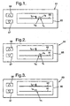
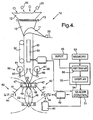
- a timing controller according to this invention is characterized as having a display device, such as one shown at 81 in Fig. 1 adapted to display a single time axis 90 on its display screen 85 or others shown at 82,83 in Figs. 2 and 3 adapted to display two time axes 91 and 92.
- Markers are also displayed for indicating the time ta at which the moving object of interest arrives at a specified position (herein referred to as “the object arrival time” and the time tb at which a specified mechanically controllable mobile machine part will arrive at the same position (herein referred to as "the machine arrival time”.
- the object arrival time the time ta at which the moving object of interest arrives at a specified position
- the machine arrival time the time tb at which a specified mechanically controllable mobile machine part will arrive at the same position
- both markers for indicating the object arrival time ta and the machine arrival time tb are displayed on the same time axis 90.
- the two markers may be adapted to be displayed on different axes.
- the marker for indicating the object arrival time is shown both in Figs. 1 and 2 with a finite width. This is because when articles are dropped as a batch, say, into a tubularly formed film being made into a bag by a packaging machine, the articles of the batch arrive at a specified position at different times, tm and tn therefore representing the earliest arrival time and the latest arrival time, respectively. If the markers for ta and tb overlap each other, or are at a same horizontal position, this means that the object and the machine part "encounter".
- the machine arrival time tb can be adjusted by adjusting the mode of operation of the mobile machine part.
- numerals 96 and 97 respectively indicate an up key and a down key for changing the mode of operation in such a way that the arrival of the mobile machine part at the specified position will be delayed or accelerated, and the machine arrival time tb displayed on the screen 85 will be shifted to the right or to the left.
- the controllably mobile machine part is a pair of seal jaws of a form-fill-seal packaging machine, to be described below more in detail
- the purpose of the timing control will be to prevent the jaws from closing too early and catching any of the articles being dropped into a tubularly formed film.
- the marker for the object arrival time may be displayed so as to indicate the earliest arrival time tm of the dropped articles and a target time interval of a specified finite duration within which the seal jaws are to clamp the film in between.
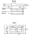
- Fig. 4 shows a vertical pillow type form-fill-seal packaging machine 10 of a generally known kind, comprising a former 11 for bending an elongated film 20 into a tubular form, a pair of pull-down belts 30 (only one of the pair being visible in Fig. 4) disposed below the former 11 for supporting the tubularly formed film 20 by adsorption from its sides to pull it downward, a longitudinal sealer 32 for longitudinally sealing the mutually overlapping side edges of the tubularly formed film 20, and a pair of transverse sealers 40 for thermally sealing and cutting in a horizontal direction the longitudinally sealed tubular film 20 so as to produce a bag 22 of a specified size.
- Each transverse sealer 40 comprises an elongated rotary member (“arm”) 41 adapted to rotate in the direction of motion of the film 20 and a seal jaw 42 attached to the free end of the arm 41 such that the pair of seal jaws 42 will clamp the film 20 in between for thermally sealing it.
- the arms 41 are controllably rotated by a servo motor (“the arm-rotating motor”) 43, horizontally slidable axes of rotation 44 of the arms 41 are moved reciprocatingly back and forth horizontally towards and away from each other by means of another servo motor (“axis-shifting motor”) 45 such that the pair of the seal jaws 42 will travel in D-shaped trajectories in a plane-symmetric relationship with respect to each other, as shown in part by broken lines in Fig. 4.
- Shutter plates 47 are attached to the upper surfaces of the seal jaws 42 so as to be horizontally pushed towards each other by means of springs (not shown) such that they close on the film 20 before the seal jaws 42 engage each other to thereby prevent articles being dropped from invading the seal surface at the top of the bag 22 across which it is sealed.
- Stripping bars 48 are similarly attached to the lower surfaces of the seal jaws 42 so as to be horizontally extendable by means of springs (not shown). These stripping bars 48 are adapted to be closed immediately before the film 20 is sealed while the seal jaws 42 travel on the straight-line portions of their D-shaped trajectories such that articles being dropped are prevented from invading the seal surface.
- Fig. 4 also shows a chute 12, which may be a part of a combinational weigher and through which articles 25 of a batch weighed thereby to be packaged are dropped into a receiving hopper 13 disposed above the former 11.
- a sensor 15 is disposed on the path of the articles dropped through the chute 12. Since the purpose of this sensor 15 is to detect the articles being dropped but since the dropped articles 25 individually travel on varied trajectories, it comprises a light emitter and a light receiver capable of covering an entire plane through which the articles 25 must pass.
- Fig. 4 shows the sensor 15 between the hopper 13 and the chute 12, it may be positioned somewhat lower if the film 20 is made of a transparent material.
- the packaging machine 10 includes a control system which incorporates a timing controller 50 for setting a delay time td from when the sensor 15 detects a falling article until the transverse sealers 40 clamp the film 20 in between, a sealer controlling means 51 for controlling the motion of the arm-rotating and axis-shifting motors 43 and 45 so that the film 20 will be clamped between the transverse sealers 40 with the timing determined by the delay time td set by the timing controller 50, and a memory 52 for storing the time of fall ("the falling time") tf from when the dropping articles 25 are detected by the sensor 15 until they pass the position at which the film 20 is clamped ("the clamping position" where the transverse sealers 40 are shown by solid lines in Fig.
- a timing controller 50 for setting a delay time td from when the sensor 15 detects a falling article until the transverse sealers 40 clamp the film 20 in between
- a sealer controlling means 51 for controlling the motion of the arm-rotating and axis-shifting motors 43 and 45
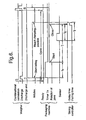
- the delay time td is set to be shorter than the falling time tf, as shown in the time chart of Fig. 5, such that the transverse sealers 40 will clamp the film 20 before the articles 25 falling inside the tubular film 20 reach the clamping position.
- the travel time tj of the seal jaws 42 from when they start their motion from their specified initial positions is known for each mode of motion. The starting time of the motion of the seal jaws 42 is therefore determined from the delay time td as shown in Fig. 5.
- the timing controller 50 of the control unit for the packaging machine 10 includes a display device 54 on which the delay time td and the falling time tf are displayed (either on one time axis or on two time axes, as described above with reference to Figs. 1 and 2).
- the timing controller 50 may be operated either manually or automatically.
- the input of the delay time td may be effected by means of an up key and a down key, as explained above with reference to Figs. 1, 2 and 3.
- the falling time tf may be experimentally measured and stored in the memory 52, and this stored value may be used to calculate the delay time td, for example, as a specified fraction of the falling time.
- the manual and automatic operation modes may be made switchable such that the delay time td can be automatically set although, if articles with a different shape are to be packaged, the corresponding falling time tf may be different.
- the delay time td can be manually corrected accordingly, say, by a key input through an input means 55.
- the falling time tf of articles changes somewhat, depending on the shape of the articles but can be measured accurately by using a transparent film, and a measured value thus obtained is stored in the memory 52.
- the shortest of the measured falling times should preferably be stored. If the falling time tf changes significantly, depending on the kind of articles to be packaged, the falling time tf for each kind of articles may be stored in the memory 52.
- the type of the articles to be packaged may be specified through the input means 55 to cause a retrieving means 56 to retrieve the falling time tf of the specified kind of articles from the memory 52 and to have it displayed on the display device 54.
- Fig. 4 shows transverse sealers 40 of a rotary type with the arms 41 undergoing a continuous rotary motion
- the invention may be equally well incorporated in a packaging machine with transverse sealers of a type which undergo a so-called "box motion" whereby seal jaws are caused to move along box-shaped trajectories with horizontal and vertical parts.
- the time chart shown in Fig. 5 is applicable to transverse sealers of whichever type. Since the delay time td from the start until the transverse sealers 40 engage each other is determined as soon as the speed of operating the packaging machine 10 is set, the starting time for the transverse sealers 40 is automatically determined once the delay time td is set.
- the sealer controlling means 51 then serves to start the motion of the seal jaws 42 at the start time thus calculated from the delay time td and to thereafter operate the arm-rotating and axis-shifting motors 43 and 45 in known manners such that the transverse sealers 40 will engage together at the clamping position at the set delay time td.
- the seal jaws 42 are set at their specified initial positions and a ready signal is outputted to the weigher.
- the weigher Upon receiving this ready signal from the packaging machine 10, the weigher carries out a combinational calculation, discharges articles 25 having a total weight within a specified range in a manner well known in the art of combinational weighing and outputs a discharge-end signal to the packaging machine 10, indicating that a batch of articles has been discharged. If the combinational calculation was unsuccessful, a failure signal may be caused to be outputted instead of a discharge-end signal.
- the packaging machine 10 Upon receiving the discharge-end signal from the weigher, the packaging machine 10 starts a timer Tx (not shown). After a specified time period tX, the sealer controlling means 51 controls the arm-rotating and axis-shifting motors 43 and 45 so as to cause the seal jaws 42 to undergo a specified rotary motion such that they reach the clamping position after a travel time tj and the shutter plates 47 engage together. Immediately thereafter, the fastest dropping ones of the articles 25 being dropped will reach the clamping position but since the shutter plates 47 are already closed, the articles 25 are not caught between the seal jaws 42. Next, the seal jaws 42 move straight downward, the stripper bars stripping the bag 22.
- the jaws 42 When they reach the seal-start positions indicated by numeral 46 where the arms 41 are horizontal (not shown), the jaws 42 begin to thermally seal the bag 22 while moving vertically downward. After the bag 22 is thus sealed and is cut by means of a cutter (not shown) imbedded in one of the seal jaws 42, the seal jaws 42 move in circular arcs (not completely shown) to return to their initial positions (from the seal-end positions indicated by broken lines in Fig. 4).
- the pull-down belts 30 serve to advance the film 20 by the length of one bag in synchronism with one cycle of the rotary motions of the seal jaws 42.
- the packaging machine 10 outputs a ready signal again to the weigher thereabove to start the next cycle of operations. If no discharge-end signal is outputted thereupon from the weigher, the packaging machine 10 simply waits until the beginning of the next cycle and then outputs another ready signal.
- the process described above is for the first cycle. From the second cycle onward, the sealer controlling means 51 does not use the start timer Tx but controls the motion of the seal jaws 42 according to the specified mode of steady operation described above.
- the display on the display device 54 may be as shown in Fig. 1, 2 or 3.
- three time axes 91, 92 and 93 may be displayed, one of them (93) displaying the "passing time” tc at which the dropped articles 25 pass the position of the sensor 15, another axis (92) displaying the delay time td from the moment (also referred to as the "starting time” below) when the sensor 15 detects the articles 25 until the shutter plates 47 are closed, and the third axis (91) displaying the falling time tf of the articles 25 between the position of the sensor 15 and that of the shutter plates 47.
- the falling time tf is stored in the memory 52.
- the retrieving means 56 retrieves from the memory 52 the falling time tf for the specified kind of articles and the retrieved falling time tf is caused to be displayed on the display device 54 together with a target range with a finite width, as explained above with reference to Fig. 3.
- the width of this target range is selected according to the period of the cyclic operation of the packaging machine 10, or the number of bags to be made per unit time. The shorter this period of the cycle, or the faster the packages are to be made, the smaller will be the width.
- the delay time td is adjusted by the up key 96 and the down key 97, as described above.
- the time thus set is displayed on the display device 54.
- This mode of display is advantageous in that the length of the articles and the discharge timing can be visualized. If this axis 93 is used additionally to display the passing time tc, the user can see the length of the "tails" trailing the falling articles and hence can predict the shift in the timing more reliably.
- the user operates the up key 96 and the down key 97 to move the marker for the delay time td such that it will come to a center position of the allowable range with a finite width displayed on the display device 54, as explained above.
- the starting time of the seal jaws 42 also changes. Since the travel time tj of the seal jaws 42 from their initial positions until the shutter plates 47 are closed is uniquely set according to the packaging speed, or the number of bags to be made per unit time, the starting time for the motion of the seal jaws 42 changes accordingly as the marker is moved, that is, as the delay time td is changed. As a result, the specified time period tx to be counted by the timer TX is also determined.
- the travel time tj is obtained in this example according to the position at which the shutter plates 47 close, this position may change if the bag size or the stripping distance is changed. In such a situation, the travel time tj is corrected and, if necessary, the falling time tf is also changed and displayed on the display device 54. Thus, the displayed position of the marker will be shifted, and the user operates the up key 96 and the down key 97 again to bring the marker for the delay time td to the center of the target range. Similarly as above, the specified time tx to be counted by the start timer Tx is accordingly determined, and the starting time of the seal jaws 42 is thereby also determined.
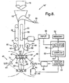
- Fig. 8 shows another packaging machine 10' controlling the timing of its operation in this manner. Since this packaging machine 10' is structured nearly identically to the packaging machine 10 shown in and described with reference to Fig. 4 above except that the sensor 15 of Fig. 4 is absent, the same or substantially equivalent components are indicated by the same numerals and are not described repetitiously.
- numeral 19 indicates a timing hopper at the bottom of the weigher disposed above the packaging machine 10'.
- the timing hopper 19 is for temporarily holding an article batch to be discharged together.
- that of Fig. 8 serves to set a delay time td between when the hopper 19 discharges a batch of weighed articles and when the transverse sealers 40 clamp the film 20.
- the memory 52 of Fig. 8 stores the falling times tf of articles of different kinds as measured from the moment when they are discharged from the timing hopper 19 above the packaging machine 10' until they reach the clamping position of the transverse sealers 40.
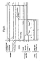
- the delay time td is set shorter than the falling time tf such that the transverse sealers 40 will be closed before the falling articles reach the clamping position, as shown in the timing chart of Fig. 9.
- the timing hopper 19 of the weigher opens or closes in response to a ready signal transmitted from the packaging machine 10'. Since the time to start moving the seal jaws 42 is automatically determined by calculating backward from the travel time tj, the sealer controlling means 51 can start the motion of the transverse sealers 40 once the travel time tj is determined.
- the functions of the display device 54, the input means 55 and the retrieving means 56 are substantially the same as described above with reference to Fig. 4.
- the packaging machine 10' of Fig. 8 will be explained more systematically next with reference to the timing chart of Fig. 9.
- the seal jaws 42 are initially at their specified initial positions.
- the weigher immediately causes the articles then in the timing hopper 19 to be discharged and outputs a discharge-end signal back to the packaging machine 10'.
- the weigher then carries out a combinational calculation, selects a combination of articles in a manner known in the art of combinational weighing, discharges them into the timing hopper 19, which is now empty, and waits for the next ready signal from the packaging machine 10'.
- a failure signal may be outputted instead of a discharge-end signal. If a discharge-end signal is received, the packaging machine 10' starts the timer Tx. The subsequent operations by the timing controller 50 are the same as explained above with reference to Figs. 4 and 6.
- the delay time td and the falling time tf are measured from the moment when the timing hopper 19 discharges the articles but the display on the time axis or axes on the screen of the display device 54 is substantially the same as described above.
- the delay time td, the falling time tf, the travel time tj of the seal jaws 42 from their initial positions until the transverse sealers 40 clamp together and the time tx to be counted by the timer Tx are related as shown in Fig.
- the time tx to be counted is automatically determined as the marker is set within the range for the target region, as explained above, and the sealer controlling means 51 serves to start the motion of the transverse sealers 40 when the timer Tx counts up the time tx thus set.
- the packaging machines 10 and 10' may be provided also with a pair of gates 60, although their presence was ignored for convenience when the operations of the packaging machines 10 and 10' were described above.
- the articles to be dropped for packaging are sugar-coated or salt-coated and/or easily breakable like potato chips, powders or small pieces separated from main bodies of the articles tend to keep dropping into the bag constantly in a continuous motion. In such a case, even if the tubularly formed film 20 is stripped in a conventional manner by means of the stripping bars 48, these powders and small pieces are easily caught in the sealing surface.
- the gates 60 are provided between the pull-down belts 30 And the transverse sealers 40 and are temporarily closed before the seal jaws 42 are closed so as to create an empty space containing no articles between the closed position of the gates 60 and the clamping position of the seal jaws 42.
- the gates 60 comprise L-shaped members 62 attached to the axes of rotation of rotary cylinders 61 and are adapted to swing instantaneously by 90 degrees from vertical positions (shown by solid lines) to horizontal positions (shown by broken lines) so as to sandwich the tubular film 20 therebetween.
- a gate mechanism is well known and hence its detailed structure will not be illustrated.
- these gates 60 may comprise a pair of plates adapted to move horizontally towards or away from each to open or close. In all situations, the opening and closing of the gates 60 must be effected quickly so as not to cause any jamming in the film 20 which is moving downward therebetween continuously.
Landscapes
- Engineering & Computer Science (AREA)
- Mechanical Engineering (AREA)
- Physics & Mathematics (AREA)
- General Physics & Mathematics (AREA)
- Automation & Control Theory (AREA)
- Human Computer Interaction (AREA)
- Manufacturing & Machinery (AREA)
- Containers And Plastic Fillers For Packaging (AREA)
- Package Closures (AREA)
- Basic Packing Technique (AREA)
- Control By Computers (AREA)
- Testing And Monitoring For Control Systems (AREA)
Claims (7)
- Verpackungsmaschine (10), vorgesehen unter einer Produktfalleinrichtung (12, 13, 15) zum unterbrochenen Fallenlassen einer zu verpackenden Produktcharge, wobei die Verpackungsmaschine umfasst:wobei die Verzögerungszeit (td) kürzer eingestellt ist als die Fallzeit (tf), so dass die Querdichter die Folie klemmen, bevor die fallengelassenen Produkte die Klemmposition erreichen.eine Folientransporteinrichtung (11, 30), um eine verlängerten Folie (20) in eine Rohrform zu biegen und die rohrförmige Folie in einer Längsrichtung zu transportieren;einen länglichen Dichter (32), um Seitenkanten der rohrförmigen Folie in der Längsrichtung miteinander zu dichten;ein Paar von Querdichtern (42), um die in Längsrichtung gedichtete Folie quer zu der Längsrichtung in einer Klemmposition zum Herstellen einer Tasche dazwischen zu klemmen;eine Startanzeigeeinrichtung (15), um eine Startzeit anzuzeigen, zu der fallengelassene Produkte eine spezifizierte Startposition passieren;eine Verzögerungszeiteinstelleinrichtung (50), um eine Verzögerungszeit (td) zwischen der Startzeit und einer Klemmzeit einzustellen, wenn die Querdichter die längsgedichtete Folie bei der Klemmposition klemmen;einer Dichtersteuereinrichtung (51), um zu bewirken, dass die Querdichter sich von spezifizierten Anfangspositionen bewegen, um so die Klemmposition zu der Klemmzeit zu erreichen; undeiner Erinnerungseinrichtung (52) zum Speichern einer Fallzeit (tf), die von den durch die Produktfalleinrichtung fallengelassenen Produkten genommen wird, um die Klemmposition aus der spezifizierten Startposition zu erreichen;
- Verpackungsmaschine gemäß Anspruch 1, wobei die Startbezeichnungseinrichtung einen Sensor (15) umfasst, und die Startzeit ist, wenn der Sensor durch die Produktfalleinrichtung fallengelassene Produkte erfasst, und die Startposition ist, wo der Sensor die Produkte zu der Startzeit erfasst.
- Maschine gemäß Anspruch 1 oder Anspruch 2, wobei die Produktfalleinrichtung als Startanzeigeeinrichtung dient, und die Startzeit dann ist, wenn eine Produktcharge durch die Artikelfalleinrichtung fallengelassen wird, und die Startposition ist, wo die Produkte durch die Artikelfalleinrichtung zu der Startzeit fallengelassen werden.
- Maschine gemäß jedem der Ansprüche von 1 bis 3, außerdem mit einer Anzeigevorrichtung (54) um darauf Markierungen anzuzeigen, die für die durch die Verzögerungszeiteinstelleinrichtung eingestellte Verzögerungszeit und die in der Speichereinrichtung gespeicherte Fallzeit bezeichnend sind, wobei die Anzeigevorrichtung außerdem eine erste Zeitachse und eine zweite Zeitachse anzeigt, die im gegenseitig parallel zueinander sind, und die Verzögerungszeit durch eine der beiden Markierungen entlang der ersten Zeitachse angezeigt ist und die Fallzeit durch die andere der Markierungen entlang der zweiten Zeitachse angezeigt ist.
- Verpackungsmaschine gemäß Anspruch 4, wobei die einzige Vorrichtung (54) außerdem eine dritte Zeitachse anzeigt, wobei noch eine andere Markierung entlang der dritten Zeitachse angezeigt wird, und eine verstrichene Zeit bezeichnet, zu der der Sensor die durch die Produktfalleinrichtung fallengelassenen Produkte erfasst.
- Maschine gemäß jedem der vorangehenden Ansprüche, wobei die Speichereinrichtung (52) Fallzeiten von Produkten verschiedener Bauart speichert, und die Verpackungsmaschine außerdem eine Einrichtung umfasst, die es einem Benutzer gestattet, eine der verschiedenen Fallzeiten zu spezifizieren, und eine Abrufeinrichtung, um die Fallzeit der spezifizierten Art von Produkten aus der Speichereinrichtung abzurufen und zu verursachen, dass die abgerufene Fallzeit angezeigt wird.
- Maschine gemäß jedem der vorangehenden Ansprüche, außerdem mit zwischen dem Längsdichter und den Querdichtern angeordneten Toren (60) zum Öffnen und Schließen, wobei die Tore dazu dienen, die rohrförmige Folie vorübergehend zu klemmen, bevor die Querdichter die Folie klemmen, und die Zeitverzögerungseinstelleinrichtung ebenfalls dazu dient, eine andere Verzögerungszeit zwischen der Startzeit und einer Schließzeit einzustellen, wenn die Tore schließen, um die Folie zu klemmen.
Priority Applications (1)
| Application Number | Priority Date | Filing Date | Title |
|---|---|---|---|
| EP03019659.6A EP1380910B1 (de) | 1998-05-18 | 1999-05-14 | Zeitsteuerungsmaschine und Verpackungsmaschine mit dergleichen |
Applications Claiming Priority (2)
| Application Number | Priority Date | Filing Date | Title |
|---|---|---|---|
| JP13578098 | 1998-05-18 | ||
| JP13578098A JP4229221B2 (ja) | 1998-05-18 | 1998-05-18 | 包装装置 |
Related Child Applications (1)
| Application Number | Title | Priority Date | Filing Date |
|---|---|---|---|
| EP03019659.6A Division EP1380910B1 (de) | 1998-05-18 | 1999-05-14 | Zeitsteuerungsmaschine und Verpackungsmaschine mit dergleichen |
Publications (3)
| Publication Number | Publication Date |
|---|---|
| EP0959397A2 EP0959397A2 (de) | 1999-11-24 |
| EP0959397A3 EP0959397A3 (de) | 2001-02-07 |
| EP0959397B1 true EP0959397B1 (de) | 2004-08-04 |
Family
ID=15159688
Family Applications (2)
| Application Number | Title | Priority Date | Filing Date |
|---|---|---|---|
| EP03019659.6A Expired - Lifetime EP1380910B1 (de) | 1998-05-18 | 1999-05-14 | Zeitsteuerungsmaschine und Verpackungsmaschine mit dergleichen |
| EP99303778A Expired - Lifetime EP0959397B1 (de) | 1998-05-18 | 1999-05-14 | Verpackungsmaschine |
Family Applications Before (1)
| Application Number | Title | Priority Date | Filing Date |
|---|---|---|---|
| EP03019659.6A Expired - Lifetime EP1380910B1 (de) | 1998-05-18 | 1999-05-14 | Zeitsteuerungsmaschine und Verpackungsmaschine mit dergleichen |
Country Status (4)
| Country | Link |
|---|---|
| US (3) | US6421981B1 (de) |
| EP (2) | EP1380910B1 (de) |
| JP (1) | JP4229221B2 (de) |
| DE (1) | DE69919074T2 (de) |
Families Citing this family (32)
| Publication number | Priority date | Publication date | Assignee | Title |
|---|---|---|---|---|
| DK174177B1 (da) * | 2000-08-16 | 2002-08-12 | Claus Thomsen | Indretning og fremgangsmåde til netning af træer |
| NL1016524C2 (nl) * | 2000-11-01 | 2002-05-07 | Aquarius Bv | Vorm-, vul- en sluitmachine. |
| JP4526199B2 (ja) * | 2001-02-20 | 2010-08-18 | 株式会社東京自働機械製作所 | 縦形製袋充填包装機の充填サイクル調整装置およびその調整方法 |
| JP4557298B2 (ja) * | 2001-06-27 | 2010-10-06 | 株式会社イシダ | 縦型製袋包装機 |
| JP2003072721A (ja) * | 2001-09-05 | 2003-03-12 | Ishida Co Ltd | 物品処理装置 |
| JP2003072720A (ja) * | 2001-09-05 | 2003-03-12 | Ishida Co Ltd | 縦型製袋包装機 |
| DE10259904A1 (de) * | 2002-12-20 | 2004-07-01 | Rovema Verpackungsmaschinen Gmbh | Verpackungsmaschine sowie Verfahren zur Regelung einer Verpackungsmaschine |
| DE102004047207A1 (de) * | 2004-09-29 | 2006-03-30 | Rovema Verpackungsmaschinen Gmbh | Verfahren und Vorrichtung zum Bewegen einer Schweißbacke |
| DE102004049375A1 (de) * | 2004-10-09 | 2006-04-13 | Rovema Verpackungsmaschinen Gmbh | Verfahren und Vorrichtung zum Positionieren einer Schweißbacke |
| US8020358B2 (en) | 2004-11-02 | 2011-09-20 | Sealed Air Corporation (Us) | Apparatus and method for forming inflated containers |
| JP4069112B2 (ja) * | 2004-11-24 | 2008-04-02 | 大和製衡株式会社 | 組合せ秤 |
| JP2007223659A (ja) * | 2006-02-27 | 2007-09-06 | Taisei Lamick Co Ltd | 充填包装装置 |
| DE102006022193B4 (de) * | 2006-05-12 | 2009-08-27 | Rovema - Verpackungsmaschinen Gmbh | Vertikale Schlauchbeutelmaschine mit zwei Linearmotoren |
| DE102006022192B4 (de) * | 2006-05-12 | 2009-08-27 | Rovema - Verpackungsmaschinen Gmbh | Vorrichtung zum Verschweißen einer Folienbahn |
| WO2008107495A1 (es) * | 2007-03-08 | 2008-09-12 | Ulma Packaging Technological Center, S. Coop. | Sistema y método de envasado vertical |
| JP5235459B2 (ja) * | 2008-03-19 | 2013-07-10 | 株式会社川島製作所 | 縦型製袋包装システム及びそのタイミング制御方法 |
| CH700243A1 (de) * | 2009-01-12 | 2010-07-15 | Ferag Ag | Computergesteuertes fördersystem und förderverfahren. |
| EA017840B1 (ru) * | 2009-01-15 | 2013-03-29 | Цубакимото Когьо Ко., Лтд. | Пакетировочно-упаковочная машина и способ пакетирования и упаковки объекта |
| DE102009061006A1 (de) † | 2009-04-16 | 2010-11-04 | Multivac Sepp Haggenmüller Gmbh & Co. Kg | Verpackungsmaschine und Anzeigevorrichtung für eine Verpackungsmaschine |
| US9957075B2 (en) | 2009-12-30 | 2018-05-01 | Philip Morris Usa Inc. | Method and apparatus for producing pouched tobacco product |
| DE102012218844A1 (de) * | 2012-10-16 | 2014-04-17 | Hastamat Verpackungstechnik Gmbh | Verfahren zur Herstellung von Verpackungseinheiten in einer Schlauchbeutelmaschine |
| JP5803882B2 (ja) * | 2012-11-20 | 2015-11-04 | キヤノンマーケティングジャパン株式会社 | 錠剤取出し装置 |
| JP2016047740A (ja) * | 2014-08-27 | 2016-04-07 | キヤノンマーケティングジャパン株式会社 | 分包装置、及びその制御方法とプログラム |
| US20170247130A1 (en) * | 2014-09-03 | 2017-08-31 | Taisei Lamick Co., Ltd. | Fill packaging method and fill packaging machine for liquid packing material |
| CN104309839B (zh) * | 2014-09-26 | 2016-08-24 | 成都三可实业有限公司 | 一种用于纵封装置的纵封盘调节机构 |
| JP6534919B2 (ja) * | 2015-11-30 | 2019-06-26 | 株式会社イシダ | 製袋包装機 |
| JP6883834B2 (ja) * | 2016-09-16 | 2021-06-09 | 株式会社イシダ | タイミング調整可能な包装機 |
| JP7054158B2 (ja) * | 2017-08-18 | 2022-04-13 | 株式会社イシダ | 商品処理装置 |
| CN107678359A (zh) * | 2017-10-30 | 2018-02-09 | 廖忠民 | 一种自动枕头的控制方法 |
| JP7071729B2 (ja) * | 2017-11-01 | 2022-05-19 | 株式会社イシダ | 製袋包装機 |
| JP2021107251A (ja) * | 2019-12-27 | 2021-07-29 | 株式会社イシダ | 製袋包装機 |
| JP7468900B2 (ja) * | 2020-09-29 | 2024-04-16 | 株式会社川島製作所 | 縦型製袋充填包装機 |
Family Cites Families (14)
| Publication number | Priority date | Publication date | Assignee | Title |
|---|---|---|---|---|
| US4332123A (en) | 1980-06-23 | 1982-06-01 | The Mead Corporation | Packaging machine and method |
| US4574566A (en) * | 1985-01-14 | 1986-03-11 | Doboy Packaging Machinery, Inc. | Wrapping machine and method |
| US5147491A (en) * | 1986-01-31 | 1992-09-15 | Roberts Systems, Inc. | Form, fill and seal process and device |
| US5168883A (en) * | 1988-07-14 | 1992-12-08 | American Decal & Mfg. Co. | Apparatus for applying tax stamps to cigarettes in cartons and for repacking cartons |
| DE69222102T2 (de) * | 1991-08-02 | 1998-03-26 | Grass Valley Group | Bedienerschnittstelle für Videoschnittsystem zur Anzeige und interaktive Steuerung von Videomaterial |
| IT1250241B (it) | 1991-12-04 | 1995-04-03 | Cavanna Spa | Macchina confezionatrice,particolarmente per la formazione di involucri del tipo flow-pack e simili e relativo procedimento di azionamento |
| US5345389A (en) | 1992-04-21 | 1994-09-06 | Vhc, Ltd. | Electronic controller for a glassware forming machine |
| US5419677A (en) | 1993-04-28 | 1995-05-30 | Cohn; Robert | Apparatus and method for programmable interleaving and stacking of sheet-carried food products |
| US5706627A (en) * | 1994-02-02 | 1998-01-13 | Tetra Laval Holdings & Finance, S.A. | Control system for a packaging machine |
| US5500938A (en) * | 1994-03-07 | 1996-03-19 | International Business Machines, Corporation | Method and apparatus for directly selecting and signalling start and stop times in an electronic calendar |
| US5724786A (en) * | 1994-09-28 | 1998-03-10 | Tetra Laval Holdings & Finance S.A. | Control system having error correcting apparatus |
| US5540035A (en) | 1994-12-07 | 1996-07-30 | Kliklok Corporation | Continuous vertical form-fill-seal packaging machine with synchronized product clamp |
| JP3585638B2 (ja) * | 1996-04-03 | 2004-11-04 | 三光機械株式会社 | 多連式自動包装機 |
| JP3750759B2 (ja) * | 1996-09-26 | 2006-03-01 | 株式会社イシダ | 製袋包装機 |
-
1998
- 1998-05-18 JP JP13578098A patent/JP4229221B2/ja not_active Expired - Fee Related
-
1999
- 1999-05-06 US US09/306,483 patent/US6421981B1/en not_active Expired - Fee Related
- 1999-05-14 EP EP03019659.6A patent/EP1380910B1/de not_active Expired - Lifetime
- 1999-05-14 DE DE69919074T patent/DE69919074T2/de not_active Expired - Lifetime
- 1999-05-14 EP EP99303778A patent/EP0959397B1/de not_active Expired - Lifetime
-
2001
- 2001-11-29 US US09/996,833 patent/US6427425B1/en not_active Expired - Fee Related
-
2002
- 2002-05-01 US US10/138,066 patent/US6646959B2/en not_active Expired - Fee Related
Also Published As
| Publication number | Publication date |
|---|---|
| US6646959B2 (en) | 2003-11-11 |
| EP1380910A3 (de) | 2004-09-29 |
| JP4229221B2 (ja) | 2009-02-25 |
| DE69919074D1 (de) | 2004-09-09 |
| JPH11321809A (ja) | 1999-11-24 |
| EP0959397A2 (de) | 1999-11-24 |
| US6421981B1 (en) | 2002-07-23 |
| US6427425B1 (en) | 2002-08-06 |
| EP1380910B1 (de) | 2013-10-02 |
| US20020121076A1 (en) | 2002-09-05 |
| US20020035822A1 (en) | 2002-03-28 |
| DE69919074T2 (de) | 2005-01-20 |
| EP1380910A2 (de) | 2004-01-14 |
| EP0959397A3 (de) | 2001-02-07 |
Similar Documents
| Publication | Publication Date | Title |
|---|---|---|
| EP0959397B1 (de) | Verpackungsmaschine | |
| US6088994A (en) | Packaging machine incorporating device for adjusting position for cutting bags | |
| EP1050460B1 (de) | Verpackungssystem mit verbessertem Produktstrom | |
| EP3385176B1 (de) | Verpackungsmaschine zur herstellung von beuteln | |
| JP4867060B2 (ja) | 包装装置 | |
| CA2532446C (en) | Automatic bagger with intelligent programmable controller | |
| EP0930233B1 (de) | Verfahren und Vorrichtung zum Einstellen der Schneideposition von Beuteln und mit diesen ausgestattete Verpackungsmaschine | |
| JP2009107751A (ja) | 搬入装置及び包装機 | |
| JPH1077002A (ja) | 計量・包装装置および方法 | |
| JP6883834B2 (ja) | タイミング調整可能な包装機 | |
| JP2018150072A (ja) | 包装システム、及び、包装装置に対する包装環境に適した制御パラメータの設定をサポートする情報処理装置 | |
| JP3850010B2 (ja) | 縦形製袋充填包装機における横ヒートシーラの原点復帰制御装置及びその原点復帰制御方法 | |
| GB2127769A (en) | A bag forming and filling machine | |
| JP2821470B2 (ja) | 包装機の制御装置 | |
| JP2000033914A (ja) | 包装機におけるカット位置の調整方法及び装置 | |
| JPH09226730A (ja) | 充填包装機におけるサンプル小袋取り出し装置 |
Legal Events
| Date | Code | Title | Description |
|---|---|---|---|
| PUAI | Public reference made under article 153(3) epc to a published international application that has entered the european phase |
Free format text: ORIGINAL CODE: 0009012 |
|
| AK | Designated contracting states |
Kind code of ref document: A2 Designated state(s): DE FR GB IT |
|
| AX | Request for extension of the european patent |
Free format text: AL;LT;LV;MK;RO;SI |
|
| PUAL | Search report despatched |
Free format text: ORIGINAL CODE: 0009013 |
|
| AK | Designated contracting states |
Kind code of ref document: A3 Designated state(s): AT BE CH CY DE DK ES FI FR GB GR IE IT LI LU MC NL PT SE |
|
| AX | Request for extension of the european patent |
Free format text: AL;LT;LV;MK;RO;SI |
|
| RIC1 | Information provided on ipc code assigned before grant |
Free format text: 7G 05B 19/042 A, 7B 65B 51/30 B |
|
| 17P | Request for examination filed |
Effective date: 20010305 |
|
| AKX | Designation fees paid |
Free format text: DE FR GB IT |
|
| 17Q | First examination report despatched |
Effective date: 20030516 |
|
| GRAP | Despatch of communication of intention to grant a patent |
Free format text: ORIGINAL CODE: EPIDOSNIGR1 |
|
| RTI1 | Title (correction) |
Free format text: PACKAGING MACHINE |
|
| RTI1 | Title (correction) |
Free format text: PACKAGING MACHINE |
|
| GRAS | Grant fee paid |
Free format text: ORIGINAL CODE: EPIDOSNIGR3 |
|
| GRAA | (expected) grant |
Free format text: ORIGINAL CODE: 0009210 |
|
| AK | Designated contracting states |
Kind code of ref document: B1 Designated state(s): DE FR GB IT |
|
| REG | Reference to a national code |
Ref country code: GB Ref legal event code: FG4D |
|
| REF | Corresponds to: |
Ref document number: 69919074 Country of ref document: DE Date of ref document: 20040909 Kind code of ref document: P |
|
| ET | Fr: translation filed | ||
| PLBE | No opposition filed within time limit |
Free format text: ORIGINAL CODE: 0009261 |
|
| STAA | Information on the status of an ep patent application or granted ep patent |
Free format text: STATUS: NO OPPOSITION FILED WITHIN TIME LIMIT |
|
| 26N | No opposition filed |
Effective date: 20050506 |
|
| PGFP | Annual fee paid to national office [announced via postgrant information from national office to epo] |
Ref country code: GB Payment date: 20130521 Year of fee payment: 15 Ref country code: DE Payment date: 20130522 Year of fee payment: 15 |
|
| PGFP | Annual fee paid to national office [announced via postgrant information from national office to epo] |
Ref country code: IT Payment date: 20130527 Year of fee payment: 15 Ref country code: FR Payment date: 20130603 Year of fee payment: 15 |
|
| REG | Reference to a national code |
Ref country code: DE Ref legal event code: R119 Ref document number: 69919074 Country of ref document: DE |
|
| GBPC | Gb: european patent ceased through non-payment of renewal fee |
Effective date: 20140514 |
|
| REG | Reference to a national code |
Ref country code: DE Ref legal event code: R119 Ref document number: 69919074 Country of ref document: DE Effective date: 20141202 |
|
| REG | Reference to a national code |
Ref country code: FR Ref legal event code: ST Effective date: 20150130 |
|
| PG25 | Lapsed in a contracting state [announced via postgrant information from national office to epo] |
Ref country code: DE Free format text: LAPSE BECAUSE OF NON-PAYMENT OF DUE FEES Effective date: 20141202 Ref country code: IT Free format text: LAPSE BECAUSE OF NON-PAYMENT OF DUE FEES Effective date: 20140514 |
|
| PG25 | Lapsed in a contracting state [announced via postgrant information from national office to epo] |
Ref country code: GB Free format text: LAPSE BECAUSE OF NON-PAYMENT OF DUE FEES Effective date: 20140514 Ref country code: FR Free format text: LAPSE BECAUSE OF NON-PAYMENT OF DUE FEES Effective date: 20140602 |