EP0959167B1 - Spannmaschine mit Erkennung des Durchhangs einer textilen Warenbahn - Google Patents
Spannmaschine mit Erkennung des Durchhangs einer textilen Warenbahn Download PDFInfo
- Publication number
- EP0959167B1 EP0959167B1 EP99109869A EP99109869A EP0959167B1 EP 0959167 B1 EP0959167 B1 EP 0959167B1 EP 99109869 A EP99109869 A EP 99109869A EP 99109869 A EP99109869 A EP 99109869A EP 0959167 B1 EP0959167 B1 EP 0959167B1
- Authority
- EP
- European Patent Office
- Prior art keywords
- material web
- web
- machine according
- sagging
- tentering machine
- Prior art date
- Legal status (The legal status is an assumption and is not a legal conclusion. Google has not performed a legal analysis and makes no representation as to the accuracy of the status listed.)
- Expired - Lifetime
Links
- 238000007665 sagging Methods 0.000 title claims description 10
- 239000004753 textile Substances 0.000 title claims description 9
- 239000004744 fabric Substances 0.000 title abstract 4
- 238000001514 detection method Methods 0.000 title description 4
- 238000007664 blowing Methods 0.000 claims abstract 2
- 239000000463 material Substances 0.000 claims description 29
- 239000007789 gas Substances 0.000 claims description 15
- 238000010438 heat treatment Methods 0.000 claims description 15
- 230000001419 dependent effect Effects 0.000 claims 1
- 238000005096 rolling process Methods 0.000 abstract 1
- 230000000694 effects Effects 0.000 description 4
- 238000001035 drying Methods 0.000 description 2
- 230000004807 localization Effects 0.000 description 2
- 230000006866 deterioration Effects 0.000 description 1
- 238000002474 experimental method Methods 0.000 description 1
- 238000009434 installation Methods 0.000 description 1
Images


Classifications
-
- D—TEXTILES; PAPER
- D06—TREATMENT OF TEXTILES OR THE LIKE; LAUNDERING; FLEXIBLE MATERIALS NOT OTHERWISE PROVIDED FOR
- D06C—FINISHING, DRESSING, TENTERING OR STRETCHING TEXTILE FABRICS
- D06C3/00—Stretching, tentering or spreading textile fabrics; Producing elasticity in textile fabrics
- D06C3/02—Stretching, tentering or spreading textile fabrics; Producing elasticity in textile fabrics by endless chain or like apparatus
-
- B—PERFORMING OPERATIONS; TRANSPORTING
- B65—CONVEYING; PACKING; STORING; HANDLING THIN OR FILAMENTARY MATERIAL
- B65H—HANDLING THIN OR FILAMENTARY MATERIAL, e.g. SHEETS, WEBS, CABLES
- B65H23/00—Registering, tensioning, smoothing or guiding webs
- B65H23/02—Registering, tensioning, smoothing or guiding webs transversely
- B65H23/022—Registering, tensioning, smoothing or guiding webs transversely by tentering devices
- B65H23/028—Registering, tensioning, smoothing or guiding webs transversely by tentering devices by clips
-
- F—MECHANICAL ENGINEERING; LIGHTING; HEATING; WEAPONS; BLASTING
- F26—DRYING
- F26B—DRYING SOLID MATERIALS OR OBJECTS BY REMOVING LIQUID THEREFROM
- F26B13/00—Machines and apparatus for drying fabrics, fibres, yarns, or other materials in long lengths, with progressive movement
- F26B13/10—Arrangements for feeding, heating or supporting materials; Controlling movement, tension or position of materials
- F26B13/12—Controlling movement, tension or position of material
-
- B—PERFORMING OPERATIONS; TRANSPORTING
- B65—CONVEYING; PACKING; STORING; HANDLING THIN OR FILAMENTARY MATERIAL
- B65H—HANDLING THIN OR FILAMENTARY MATERIAL, e.g. SHEETS, WEBS, CABLES
- B65H2701/00—Handled material; Storage means
- B65H2701/10—Handled articles or webs
- B65H2701/17—Nature of material
- B65H2701/174—Textile; fibres
Definitions
- the invention relates to a tensioning machine for heat treatment a textile web corresponding to the Preamble of claim 1.
- the web of goods for example, when it is received in needle bars
- the web of goods has its heat treatment inside the tenter in the area of the web infeed often a lower width tension on than at the web outlet, where the shrinkage of the Weft threads and / or warp threads has expired and one Final stability of the web is reached.
- DE-A-195 20 637 describes a tensioning machine for heat treatment a textile web known in the sense of a continuously constant product quality Misorientation of the web (in particular strong deflection movements of the web in the direction of one and / or other side) immediately recognized and can be corrected reliably.
- the Web with regard to sag with the help of Light transmitters and receivers continuously monitored. When a predetermined sag is exceeded a rule intervention for returning sagging web sections in the area of the web transport level performed.
- Tensioner will be those emitted by the light transmitters Rays of light essentially in the longitudinal direction directed by the tensioner, the Rays of light on one side of the web approximately in Direction of transport and on the other side of the web approximately opposite to the direction of transport of the web be sent through the tenter.
- the order of light transmitter and light receiver outside The tensioning machine is particularly suitable for high-temperature applications Tensioner designs such as dryers and / or fusing machines of particular advantage.
- the invention is therefore based on the object Tensioning machine for the heat treatment of a textile web according to the preamble of claim 1 to improve that the means of detecting a Sag of the web without problems even at high temperatures Tensioners can be used and also a localization of the sag in the direction of transport enable.
- the means for recognizing a Sag of the web by two at a distance from each other arranged contact elements formed at a predetermined sag of the web with this in Come into contact, thereby closing a circuit becomes.
- the contact elements are also with a Control device in connection when closed Circuit correcting the sag of the web causes.
- the invention makes use of the idea that at wet material webs can also be used with usable current signals are achieved.
- the current signals increase with increasing Dryness of the textile web is less, however in the area of sag detection, namely in the first fields of the tensioning machine, i.e. in the wet area, so large that a corresponding control signal is generated can be.
- the reduction of at least transversely to the direction of transport sag of the web arising from the web can be realized particularly easily if the device for heat treatment of the web Nozzle devices for inflating tempered gases the side of the web facing them is formed.
- a control intervention to correct the sag can then in particular by changing the gas flow, especially with regard to the amount of gas from the nozzles of the Nozzle devices are made.
- the control device stands in this case, for example, with the blower Nozzle device for changing the speed or a Adjustment flap inside the nozzle device in Connection.
- the contact elements can be used, for example, as contact rails or contact roles are formed.
- the contact elements can be in the transport direction of the web arranged side by side or one behind the other become.
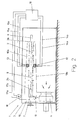
- a tensioning machine 1 is for heat treatment, especially for drying and / or fixing a textile Web 2 formed.
- the web 2 will during this heat treatment in the wide-spread state continuously through the tenter 1 transported through.
- the tensioning machine 1 contains a machine housing in the usual way 3, in its longitudinal direction in several Treatment zones can be divided and at his one end a web inlet 4 and at his at the other end a web run 5 - each in about Form of a transverse slot - has.
- the Material web 2 is thus in during its heat treatment Longitudinally transported through the tensioner 1.
- the direction of transport is with arrow 6 (Fig.1) marked.
- tensioning or transport chains 7, 8 are provided, those with clamps or needle bars like this are equipped that the web 2 on their two Longitudinal edges 2a, 2b are detected and held can.
- the transverse connection plane between the two Transport chains 7, 8 (in the holding area of the longitudinal edges of the web) is hereinafter referred to as goods web transport plane 9 designated.
- goods web transport plane 9 On at least one side the goods web transport level 9 and with practical Distance from this are nozzle devices 10 in shape of nozzle boxes for the inflation of tempered gases, in particular of warm air on the side of the web facing them arranged.
- nozzle devices 10 in shape of nozzle boxes for the inflation of tempered gases, in particular of warm air on the side of the web facing them arranged.
- the Goods transport level 9 nozzle boxes in the form of a upper nozzle box 10a and a lower nozzle box 10b is provided, with a nozzle device 10 Blower 11 for generating air circulation as well at least one control flap 19 belong to each web side a treatment gas in a required adjustable or controllable amount to be able to supply.
- the location of the web 2 is essentially by the Tension or transport chains 7, 8 and the amount of determined by the inflated gases 10 gases. As already explained at the beginning, there are many Factors such as the structure of the web, its width, the Basis weight of the web, its elasticity and the like, that affect the location of the web 2 can.
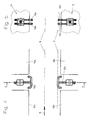
- the contact elements on both sides of the web 2 or the web transport level 9 provided.
- the contact elements shown in Figures 4 and 5 12a, 12b and 13a, 13b are spaced apart arranged, curved wire electrodes formed.
- the contact elements 13a, 13b are over Control lines 15a, 15b with the control device 16 connected.
- the control device 16 effects depending on the Control signal of the contact elements a correction of Sag by being in the illustrated embodiment 2 a device via lines 17a, 17b 18 controls to adjust the flap 19.
- Adjustment of the flap 19 can the ratio of the the upper and lower nozzle boxes 10a, 10b flowing Amount of treatment gas can be changed. So will with a sag of the web 2 in the direction of the lower Nozzle box 2b the amount of treatment gas in the lower nozzle box 10b in relation to the upper nozzle box 10a can be increased.
- the contact elements have the particular advantage that also in the hot area of the tensioner, where the Sag occurs as expected, be installed can.
- the tensioning machine shown in Fig.1 consists of three treatment zones or fields, each in two half fields can be divided. Each half field points a separate fan 11.
- 6 and 7 are means 12 ', 13' for recognition a sag of the web 2 according to a second Embodiment shown.
- the contact elements by contact rollers 12'a, 12'b or 13'a, 13'b formed.
- the contact rollers offer when touched with the web 2, as shown in Figures 6, 7 is, according to the contact rails Fig. 4 and 5 larger contact area. Otherwise in in an analogous manner by contacting the web with the related ones both contact roles the circuit closed.
- FIG 3 is a clamping machine 1 'according to a second Embodiment shown, which is different from the embodiment according to Figure 1 only in the type of generation the air circulation differs within a half field. While according to Fig.1 for the upper and lower Nozzle box 10a, 10b only one blower 11 and a cooperating with this adjustment flap 19 is provided was, are for the embodiment according to Fig.3 for the upper and lower nozzle boxes, respectively separate blowers 11a, 11b are provided. There is no need to follow this in this embodiment, the adjustment flap.
- means are also in this embodiment provided to detect a sag of the web, which cooperate with a control device 16.
- the one to be effected by the control device 16 Any slack correction can be done with this Embodiment by changing the speed one or both fans 11a, 11b.
- the contact elements shown in Figures 4 and 5 or 6 and 7 are particularly characterized by that they can be used in the hot area of the clamping machines without any problems can be arranged and also special can be manufactured inexpensively.
Landscapes
- Engineering & Computer Science (AREA)
- Textile Engineering (AREA)
- Mechanical Engineering (AREA)
- General Engineering & Computer Science (AREA)
- Treatment Of Fiber Materials (AREA)
- Force Measurement Appropriate To Specific Purposes (AREA)
- Controlling Rewinding, Feeding, Winding, Or Abnormalities Of Webs (AREA)
Description
- Fig.1
- eine schematische Aufsicht einer Spannmaschine gemäß einem ersten Ausführungsbeispiel,
- Fig.2
- eine schematische Schnittdarstellung längs der Linie II-II der Fig.1,
- Fig.3
- eine schematische Aufsicht einer Spannmaschine gemäß einem zweiten Ausführungsbeispiel,
- Fig. 4
- eine schematische Seitenansicht der Mittel zur Erkennung eines Durchhangs der Warenbahn gemäß einem ersten Ausführungsbeispiel,
- Fig.5
- eine Schnittdarstellung längs der Linie V-V der Fig.4,
- Fig.6
- eine schematische Seitenansicht der Mittel zur Erkennung eines Durchhangs der Warenbahn gemäß einem zweiten Ausführungsbeispiel und
- Fig.7
- eine Schnittdarstellung längs der Linie VII-VII der Fig.6.
Claims (11)
- Spannmaschine (1; 1') zur Wärmebehandlung einer textilen Warenbahn (2), die im breitgespannten Zustand fortlaufend durch die Maschine hindurchtransportiert und dabei wärmebehandelt wird, enthaltenddadurch gekennzeichnet, daßa) ein Maschinengehäuse (3) mit einem Warenbahneinlauf (4) an einem Gehäuseende und einem Warenbahnauslauf (5) am anderen Gehäuseende,b) Einrichtungen (7, 8) zum Breitspannen und Längstransportieren der Warenbahn vom Warenbahneinlauf zum Warenbahnauslauf,c) auf wenigstens einer Seite der Warenbahn (2) angeordnete Einrichtungen (10) zur Wärmebehandlung der Warenbahn,d) Mittel (12, 13; 12', 13') zur Erkennung eines zumindest quer zur Transportrichtung der Warenbahn entstehenden Durchhangs der Warenbahn, die auf wenigstens einer Seite der Warenbahn angeordnet sind,e) sowie eine Steuereinrichtung (16), die in Abhängigkeit eines Steuersignals der Mittel zur Erkennung eines Durchhangs der Warenbahn eine Korrektur des Durchhangs bewirkt,
die Mittel zur Erkennung eines Durchhangs der Warenbahn durch zwei mit Abstand voneinander angeordnete Kontaktelemente (12a, 12b; 12'a, 12'b) gebildet werden, die bei einem vorbestimmten Durchhang der Warenbahn mit dieser in Berührung kommen und dadurch ein Stromkreis geschlossen und das Steuersignal für die Steuereinrichtung (16) erzeugt wird. - Spannmaschine nach Anspruch 1, dadurch gekennzeichnet, daß die Kontaktelemente als Kontaktschienen (12a, 12b, 13a, 13b) ausgebildet sind.
- Spannmaschine nach Anspruch 1, dadurch gekennzeichnet, daß die Kontaktelemente als Kontaktrollen (12'a, 12'b, 13'a, 13'b) ausgebildet sind.
- Spannmaschine nach Anspruch 1, dadurch gekennzeichnet, daß die Einrichtungen (10) zur Wärmebehandlung der Warenbahn (2) auf beiden Seiten der Warenbahn angeordnet sind.
- Spannmaschine nach einem der vorhergehenden Ansprüche, dadurch gekennzeichnet, daß die Einrichtungen (10) zur Wärmebehandlung der Warenbahn durch Düseneinrichtungen zum Aufblasen temperierter Gase auf der ihnen zugewandten Seite der Warenbahn gebildet sind.
- Spannmaschine nach Anspruch 1, dadurch gekennzeichnet, daß in Transportrichtung (6) der Warenbahn (2) mehrere Kontaktelementenpaare vorgesehen sind.
- Spannmaschine nach Anspruch 1, dadurch gekennzeichnet, daß quer zur Transportrichtung der Warenbahn mehrere Kontaktelementenpaare vorgesehen sind.
- Spannmaschine nach Anspruch 5, dadurch gekennzeichnet, daß die Steuereinrichtung (16) mit den Düseneinrichtungen zur Reduzierung des Durchhangs in Verbindung steht.
- Spannmaschine nach Anspruch 8, dadurch gekennzeichnet, daß die Düseneinrichtung ein Gebläse aufweist, dessen Drehzahl von der Steuereinrichtung (16) zur Reduzierung des Durchhangs veränderbar ist.
- Spannmaschine nach Anspruch 8, dadurch gekennzeichnet, daß die Düseneinrichtung auf beiden Seiten der Warenbahn (2) angeordnete Düsenkästen (10a, 10b) aufweist, wobei das Verhältnis der aus den beiden Düsenkästen strömenden Menge eines Behandlungsgases durch die Steuereinrichtung (16) zur Korrektur eines etwaigen Durchhangs veränderbar ist.
- Spannmaschine nach Anspruch 5, dadurch gekennzeichnet, daß die Steuereinrichtung (16) mit den Düseneinrichtungen derart zusammenwirkt, daß die Gasströmung der Düseneinrichtung zur Korrektur eines etwaigen Durchhangs veränderbar ist.
Applications Claiming Priority (2)
| Application Number | Priority Date | Filing Date | Title |
|---|---|---|---|
| DE19822497A DE19822497A1 (de) | 1998-05-19 | 1998-05-19 | Spannmaschine mit Erkennung des Durchhangs einer textilen Warenbahn |
| DE19822497 | 1998-05-19 |
Publications (2)
| Publication Number | Publication Date |
|---|---|
| EP0959167A1 EP0959167A1 (de) | 1999-11-24 |
| EP0959167B1 true EP0959167B1 (de) | 2002-10-23 |
Family
ID=7868314
Family Applications (1)
| Application Number | Title | Priority Date | Filing Date |
|---|---|---|---|
| EP99109869A Expired - Lifetime EP0959167B1 (de) | 1998-05-19 | 1999-05-19 | Spannmaschine mit Erkennung des Durchhangs einer textilen Warenbahn |
Country Status (4)
| Country | Link |
|---|---|
| EP (1) | EP0959167B1 (de) |
| AT (1) | ATE226656T1 (de) |
| DE (2) | DE19822497A1 (de) |
| ES (1) | ES2185264T3 (de) |
Families Citing this family (1)
| Publication number | Priority date | Publication date | Assignee | Title |
|---|---|---|---|---|
| CN109132649A (zh) * | 2018-09-29 | 2019-01-04 | 侯马市迪科特电子科技有限公司 | 一种墙布快速平整装置 |
Family Cites Families (8)
| Publication number | Priority date | Publication date | Assignee | Title |
|---|---|---|---|---|
| DE676599C (de) * | 1936-11-22 | 1939-06-07 | Bobst & Sohn A G J | Einrichtung zum UEberwachen der Bildung einer Schleife in einer Maschine mit absatzweiser Abnahme einer ununterbrochen gefoerderten Bahn aus Pappe |
| DE735399C (de) * | 1942-06-30 | 1943-05-14 | Schaeffer & Budenberg G M B H | Fuehler zum Messen des Durchhanges von Stoffbahnen fuer Regelzwecke |
| US2725508A (en) * | 1952-03-08 | 1955-11-29 | Westinghouse Electric Corp | Electronic dancer roll control |
| CH430366A (de) * | 1965-09-16 | 1967-02-15 | Soprem Ag | Vorrichtung zum Steuern von Ab- oder Aufrollhaspeln bzw. -Trommeln für Material in Band- oder Drahtform |
| DE1968403U (de) * | 1967-01-25 | 1967-09-14 | Telefunken Patent | Anordnung zum absatzweisen transport eines bandfoermigen metallischen mediums. |
| DE7029754U (de) * | 1970-08-07 | 1970-11-26 | Textilmaschb Gera Veb | Abtastvorrichtung zur durchhangregelung von textilbahnen in oder an textilveredlungsmaschinen. |
| DE4325301C1 (de) * | 1993-07-28 | 1994-10-27 | Babcock Textilmasch | Spannrahmentrockner |
| DE19520637A1 (de) * | 1995-06-06 | 1996-12-12 | Brueckner Trockentechnik Gmbh | Verfahren und Spannmaschine zur Wärmebehandlung einer textilen Warenbahn |
-
1998
- 1998-05-19 DE DE19822497A patent/DE19822497A1/de not_active Withdrawn
-
1999
- 1999-05-19 EP EP99109869A patent/EP0959167B1/de not_active Expired - Lifetime
- 1999-05-19 DE DE59903143T patent/DE59903143D1/de not_active Expired - Fee Related
- 1999-05-19 AT AT99109869T patent/ATE226656T1/de not_active IP Right Cessation
- 1999-05-19 ES ES99109869T patent/ES2185264T3/es not_active Expired - Lifetime
Also Published As
| Publication number | Publication date |
|---|---|
| ATE226656T1 (de) | 2002-11-15 |
| DE19822497A1 (de) | 1999-11-25 |
| EP0959167A1 (de) | 1999-11-24 |
| DE59903143D1 (de) | 2002-11-28 |
| ES2185264T3 (es) | 2003-04-16 |
Similar Documents
| Publication | Publication Date | Title |
|---|---|---|
| DE2323574C3 (de) | Trockenpartie für Papiermaschinen | |
| EP0725178B2 (de) | Verfahren und Vorrichtung zum Trocknen und Krumpfen von textiler Ware | |
| EP1530699B1 (de) | Vorrichtung zur gewebe-ausrüstung | |
| EP1678452A1 (de) | Furniertrockner | |
| EP0989233B1 (de) | Trockenpartie sowie Konvektionstrockner für eine solche Trockenpartie | |
| EP0959167B1 (de) | Spannmaschine mit Erkennung des Durchhangs einer textilen Warenbahn | |
| EP0953667B1 (de) | Verfahren und Vorrichtung zum Behandeln schlauchförmiger Maschenware | |
| DE4317400A1 (de) | Vorrichtung zum Trocknen von insbesondere im Rollenoffsetdruck bedruckten Materialbahnen gekennzeichnet durch schwebende Umlenkung und mäanderförmigen Verlauf der Materialbahn | |
| DE2918833A1 (de) | Vorrichtung zum krumpfen von textiler maschenware | |
| EP1217116B1 (de) | Verfahren zum Behandeln schlauchförmiger Textilware, insbesondere Maschenware | |
| DE3325590C2 (de) | Behandlungseinheit für textile Schlauchware mit wenigstens einem zylindrischen Breithalter | |
| EP0792966B1 (de) | Kalander zum Satinieren von Papier | |
| DE19819051B4 (de) | Verfahren und Vorrichtung zum Behandeln schlauchförmiger Maschenware | |
| AT401104B (de) | Wärmebehandlungsmaschine mit förderung des behandelten gutes und verfahren zum betrieb dieser wärmebehandlungsmaschine | |
| EP0747309A2 (de) | Verfahren und Spannmaschine zur Wärmebehandlung einer textilen Warenbahn | |
| DE3118971C2 (de) | Verfahren und Vorrichtung zum Dämpfen einer textilen Warenbahn | |
| EP0063647A1 (de) | Vorrichtung zur Heissluft-Trocknung von Textilgut | |
| DE4105689C1 (de) | ||
| DE19622000A1 (de) | Trocken- und/oder Fixiervorrichtung | |
| EP0990867B1 (de) | Vorrichtung zur Wärmebehandlung einer Warenbahn | |
| DE19911963A1 (de) | Verfahren zum Kalandern einer Papierbahn und ein Kalander nach diesem Verfahren | |
| DE8111908U1 (de) | Vorrichtung zur heissluft-trocknung einer warenbahn | |
| DE102011110616A1 (de) | Transportvorrichtung und Transportverfahren für flächige Substrate | |
| DE2023902C3 (de) | Fixiervorrichtung | |
| DD202904A1 (de) | Muldenmangel |
Legal Events
| Date | Code | Title | Description |
|---|---|---|---|
| PUAI | Public reference made under article 153(3) epc to a published international application that has entered the european phase |
Free format text: ORIGINAL CODE: 0009012 |
|
| AK | Designated contracting states |
Kind code of ref document: A1 Designated state(s): AT CH DE ES FR GB IT LI |
|
| AX | Request for extension of the european patent |
Free format text: AL;LT;LV;MK;RO;SI |
|
| 17P | Request for examination filed |
Effective date: 20000329 |
|
| AKX | Designation fees paid |
Free format text: AT CH DE ES FR GB IT LI |
|
| GRAG | Despatch of communication of intention to grant |
Free format text: ORIGINAL CODE: EPIDOS AGRA |
|
| GRAG | Despatch of communication of intention to grant |
Free format text: ORIGINAL CODE: EPIDOS AGRA |
|
| GRAH | Despatch of communication of intention to grant a patent |
Free format text: ORIGINAL CODE: EPIDOS IGRA |
|
| 17Q | First examination report despatched |
Effective date: 20020516 |
|
| GRAH | Despatch of communication of intention to grant a patent |
Free format text: ORIGINAL CODE: EPIDOS IGRA |
|
| GRAA | (expected) grant |
Free format text: ORIGINAL CODE: 0009210 |
|
| AK | Designated contracting states |
Kind code of ref document: B1 Designated state(s): AT CH DE ES FR GB IT LI |
|
| REF | Corresponds to: |
Ref document number: 226656 Country of ref document: AT Date of ref document: 20021115 Kind code of ref document: T |
|
| REG | Reference to a national code |
Ref country code: GB Ref legal event code: FG4D Free format text: NOT ENGLISH |
|
| REG | Reference to a national code |
Ref country code: CH Ref legal event code: NV Representative=s name: RIEDERER HASLER & PARTNER PATENTANWAELTE AG Ref country code: CH Ref legal event code: EP |
|
| REF | Corresponds to: |
Ref document number: 59903143 Country of ref document: DE Date of ref document: 20021128 |
|
| GBT | Gb: translation of ep patent filed (gb section 77(6)(a)/1977) |
Effective date: 20030219 |
|
| REG | Reference to a national code |
Ref country code: ES Ref legal event code: FG2A Ref document number: 2185264 Country of ref document: ES Kind code of ref document: T3 |
|
| ET | Fr: translation filed | ||
| PLBE | No opposition filed within time limit |
Free format text: ORIGINAL CODE: 0009261 |
|
| STAA | Information on the status of an ep patent application or granted ep patent |
Free format text: STATUS: NO OPPOSITION FILED WITHIN TIME LIMIT |
|
| 26N | No opposition filed |
Effective date: 20030724 |
|
| PGFP | Annual fee paid to national office [announced via postgrant information from national office to epo] |
Ref country code: AT Payment date: 20070405 Year of fee payment: 9 |
|
| PGFP | Annual fee paid to national office [announced via postgrant information from national office to epo] |
Ref country code: CH Payment date: 20070413 Year of fee payment: 9 |
|
| PGFP | Annual fee paid to national office [announced via postgrant information from national office to epo] |
Ref country code: ES Payment date: 20070509 Year of fee payment: 9 |
|
| PGFP | Annual fee paid to national office [announced via postgrant information from national office to epo] |
Ref country code: DE Payment date: 20070726 Year of fee payment: 9 |
|
| PGFP | Annual fee paid to national office [announced via postgrant information from national office to epo] |
Ref country code: GB Payment date: 20070412 Year of fee payment: 9 |
|
| PGFP | Annual fee paid to national office [announced via postgrant information from national office to epo] |
Ref country code: IT Payment date: 20070616 Year of fee payment: 9 |
|
| PGFP | Annual fee paid to national office [announced via postgrant information from national office to epo] |
Ref country code: FR Payment date: 20070411 Year of fee payment: 9 |
|
| REG | Reference to a national code |
Ref country code: CH Ref legal event code: PL |
|
| GBPC | Gb: european patent ceased through non-payment of renewal fee |
Effective date: 20080519 |
|
| PG25 | Lapsed in a contracting state [announced via postgrant information from national office to epo] |
Ref country code: LI Free format text: LAPSE BECAUSE OF NON-PAYMENT OF DUE FEES Effective date: 20080531 Ref country code: CH Free format text: LAPSE BECAUSE OF NON-PAYMENT OF DUE FEES Effective date: 20080531 |
|
| PG25 | Lapsed in a contracting state [announced via postgrant information from national office to epo] |
Ref country code: AT Free format text: LAPSE BECAUSE OF NON-PAYMENT OF DUE FEES Effective date: 20080519 |
|
| REG | Reference to a national code |
Ref country code: FR Ref legal event code: ST Effective date: 20090119 |
|
| PG25 | Lapsed in a contracting state [announced via postgrant information from national office to epo] |
Ref country code: FR Free format text: LAPSE BECAUSE OF NON-PAYMENT OF DUE FEES Effective date: 20080602 Ref country code: DE Free format text: LAPSE BECAUSE OF NON-PAYMENT OF DUE FEES Effective date: 20081202 |
|
| PG25 | Lapsed in a contracting state [announced via postgrant information from national office to epo] |
Ref country code: GB Free format text: LAPSE BECAUSE OF NON-PAYMENT OF DUE FEES Effective date: 20080519 |
|
| REG | Reference to a national code |
Ref country code: ES Ref legal event code: FD2A Effective date: 20080520 |
|
| PG25 | Lapsed in a contracting state [announced via postgrant information from national office to epo] |
Ref country code: IT Free format text: LAPSE BECAUSE OF NON-PAYMENT OF DUE FEES Effective date: 20080519 |
|
| PG25 | Lapsed in a contracting state [announced via postgrant information from national office to epo] |
Ref country code: ES Free format text: LAPSE BECAUSE OF NON-PAYMENT OF DUE FEES Effective date: 20080520 |