EP0957447B1 - Méthode de controle de sauvegarde de données d'un mémoire volatile dans une mémoire non volatile dans une imprimante - Google Patents
Méthode de controle de sauvegarde de données d'un mémoire volatile dans une mémoire non volatile dans une imprimante Download PDFInfo
- Publication number
- EP0957447B1 EP0957447B1 EP99109615A EP99109615A EP0957447B1 EP 0957447 B1 EP0957447 B1 EP 0957447B1 EP 99109615 A EP99109615 A EP 99109615A EP 99109615 A EP99109615 A EP 99109615A EP 0957447 B1 EP0957447 B1 EP 0957447B1
- Authority
- EP
- European Patent Office
- Prior art keywords
- data
- memory
- printer
- saving
- nonvolatile memory
- Prior art date
- Legal status (The legal status is an assumption and is not a legal conclusion. Google has not performed a legal analysis and makes no representation as to the accuracy of the status listed.)
- Expired - Lifetime
Links
- 230000015654 memory Effects 0.000 title claims description 159
- 238000000034 method Methods 0.000 title claims description 39
- 238000004140 cleaning Methods 0.000 claims description 23
- 230000004044 response Effects 0.000 claims description 18
- 238000001514 detection method Methods 0.000 claims description 15
- 238000005259 measurement Methods 0.000 claims 1
- 230000008569 process Effects 0.000 description 20
- 230000006870 function Effects 0.000 description 7
- 230000000737 periodic effect Effects 0.000 description 5
- 238000003860 storage Methods 0.000 description 5
- 238000012544 monitoring process Methods 0.000 description 4
- 238000010586 diagram Methods 0.000 description 3
- 230000008859 change Effects 0.000 description 2
- 238000012545 processing Methods 0.000 description 2
- 230000002159 abnormal effect Effects 0.000 description 1
- 230000000295 complement effect Effects 0.000 description 1
- 238000012937 correction Methods 0.000 description 1
- 230000001186 cumulative effect Effects 0.000 description 1
- 238000013500 data storage Methods 0.000 description 1
- 230000003247 decreasing effect Effects 0.000 description 1
- 230000001419 dependent effect Effects 0.000 description 1
- 238000001035 drying Methods 0.000 description 1
- 230000000694 effects Effects 0.000 description 1
- 238000012423 maintenance Methods 0.000 description 1
- 238000004519 manufacturing process Methods 0.000 description 1
- 230000007246 mechanism Effects 0.000 description 1
Images


Classifications
-
- G—PHYSICS
- G06—COMPUTING; CALCULATING OR COUNTING
- G06K—GRAPHICAL DATA READING; PRESENTATION OF DATA; RECORD CARRIERS; HANDLING RECORD CARRIERS
- G06K15/00—Arrangements for producing a permanent visual presentation of the output data, e.g. computer output printers
-
- G—PHYSICS
- G06—COMPUTING; CALCULATING OR COUNTING
- G06K—GRAPHICAL DATA READING; PRESENTATION OF DATA; RECORD CARRIERS; HANDLING RECORD CARRIERS
- G06K2215/00—Arrangements for producing a permanent visual presentation of the output data
- G06K2215/0082—Architecture adapted for a particular function
- G06K2215/0085—Error recovery
Definitions
- the present invention relates to a printer having a nonvolatile memory and a volatile memory, both for storing information indicative of the operating condition of the printer. During printer operation, the information is initially copied from the nonvolatile memory to the volatile memory. The information in the volatile memory is then used for printer control and is updated whenever required. The updated information is saved to the nonvolatile memory.
- the invention also relates to a control method of writing of the updated information back into the nonvolatile memory.
- Correct printer operation requires certain information about the operating conditions of the printer, i.e., status information, such as the remaining ink quantity and the last head cleaning time (if it is an ink jet printer), the print head location, and how much roll paper remains (if the printer is one that prints on roll paper).
- status information such as the remaining ink quantity and the last head cleaning time (if it is an ink jet printer), the print head location, and how much roll paper remains (if the printer is one that prints on roll paper).
- head cleaning time it is well known that ink jet printers, which print by ejecting ink from nozzles of an ink jet head onto a printing medium, require regular maintenance, that is, cleaning of the nozzles, in order to sustain reliable operation. Such regular cleaning is needed to prevent problems such as clogged nozzles resulting from ink drying and becoming viscous inside the nozzles.
- This cleaning process is generally managed based on a timer and is implemented with different levels depending on how much time has passed since the last cleaning operation. Storing, in case of an ink jet printer, the last head cleaning time and level as pieces of the status information mentioned above enables the next cleaning operation to be more appropriately performed.
- the status information further includes count values such as the printed character count, the accumulated paper feed amount, and the total operating time.
- printers have commonly comprised an EEPROM (Electrically Erasable Programmable ROM), a flash memory or other type of nonvolatile memory.
- EEPROM Electrical Erasable Programmable ROM
- flash memory or other type of nonvolatile memory.
- Printer operating conditions such as those described above (also referred to as "status data" below) are maintained and updated in a volatile memory such as a DRAM, and saved to the nonvolatile memory at a regular saving period. Each time the printer resumes operation, the status data is copied from the nonvolatile memory to the volatile memory.
- status data is written into the nonvolatile memory at periodic time intervals during the operation of the above-described conventional printer. More specifically, every time a predetermined interval (the saving period), that is measured by an internal timer elapses, any current printer process is interrupted, and the printer CPU is diverted to the process for writing (saving) the data into the nonvolatile memory.
- the ability of the printer to recover from printing interruptions and restore the operating status to that before the interruption is thus improved by regularly saving the status data to the nonvolatile memory.
- the interrupted CPU task stops until the writing into the nonvolatile memory is completed.
- Printer throughput therefore drops.
- the saving time i.e., the time required for copying data from the volatile memory to the nonvolatile memory, at each saving instance be as short as possible irrespective of the amount of status data to be saved.
- nonvolatile memories allow a limited number of write cycles to a particular memory location.
- the service life of nonvolatile memories depends upon the number of write cycles they undergo per unit time. This means that when data that has not changed is written to the nonvolatile memory, the limited number of available write cycles is needlessly reduced, and memory service life is potentially shortened.
- a printer according to the pre-characterizing portion of claim 1 and a control method according to the pre-characterizing portion of claim 6 are known from US 5,479,467 A . According to this prior art the data in a respective memory area of the volatile memory is copied to the corresponding memory area in the non-volatile memory every predetermind number of increments of that data in the volatile memory.
- EP 0 345 060 A discloses an image forming device, e.g., a printer, that counts for each of a plurality of working parts the respective working time.
- the counters are implemented by means of a RAM. All counted values are copied to a non-volatile memory every predetermind number of updates of any of the counted values.
- US patents 4,458,307 and 5,533,190 deal with systems where a part of a volatile memory is saved in a non-volatile memory (such as a hard disk) when a predetermined trigger event (e.g. an imminent loss of operating power) is detected.
- a predetermined trigger event e.g. an imminent loss of operating power
- An object of the present invention is to shorten the saving time and thereby reduce the effect the saving process has on the normal printer operation.
- a further object of the present invention is to prevent data from being unnecessarily saved to the nonvolatile memory, and thereby improve the service life of the nonvolatile memory.
- the saving time is shortened and the write frequency for the individual memory areas is reduced so that life time of the nonvolatile memory is improved.
- Trigger events are events in response to which data is saved from the volatile memory to the nonvolatile memory. These trigger events preferably include detection of a reset signal from a host computer. In this case, the printer is reset based on this reset signal after data have been saved to the nonvolatile memory. Other trigger events may include events such as: the periodic lapse of a specific time interval (the saving period), turning printer power on and off, and specific control events in printer operation. These specific control events preferably include print head cleaning, ink cartridge replacement, roll paper replacement, and such operating errors as an increase in the print head temperature beyond a threshold value or a disconnection or rupture of the carriage transportation belt. It is to be noted that these specific control events depend on the type of printer to which the invention is applied. Thus, control events like print head cleaning and ink cartridge replacement apply to ink jet printers only.
- some or all of data groups corresponding to the memory areas of the volatile memory and the nonvolatile memory are classified into at least a first and a second set of data groups each set including one or more of the data groups.
- the data group or groups belonging to the first set is or are saved periodically with the saving period.
- the data group or groups belonging to the second set is or are saved in response to a predetermined one of the control events.
- Much of the data to be saved to the nonvolatile memory is updated in the volatile memory when the printer performs a particular control operation when particular control events such as those described above occur. It is therefore possible to minimize damage from data loss by saving those data to the nonvolatile memory after the control event has been completed and the data in the volatile memory updated. By also saving data that is otherwise periodically saved and also restarting the time counter measuring the saving period, an increase in the frequency of data write cycles to the nonvolatile memory can be prevented.
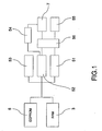
- the printer 1 shown in Fig. 1 is - by way of example only - a serial ink jet printer capable of printing to both cut-sheet forms and roll paper.
- This printer 1 comprises an EEPROM 5 for storing status data, a RAM 3 for temporarily storing status data as it is updated during printer operation, various control means 51 to 56 for controlling the copying (saving) of the status data from the RAM 3 to the EEPROM 5 and from the EEPROM 5 to the RAM 3, and a counter 7.
- Both memories, the EEPROM 5 and the RAM 3, (or a respective part of each) are logically divided into a plurality of memory areas for storing status data such those explained above.
- the status data is in turn divided into a corresponding plurality of data groups and each data group is assigned to a respective one the of memory areas.
- the individual data groups are saved at different times.
- the memories are logically divided into six memory areas A1 to A6 each, and the status data are correspondingly grouped into six data groups.
- These six data groups are preferably classified into a number of sets. Among these are at least a first set of one or more data groups that is or are periodically saved to the nonvolatile memory at a predetermined saving period as counted by counter 7, and a second set of one or more data groups that is or are saved to the nonvolatile memory every time a predetermined control event (or one of multiple specific control events) occurs.
- saving of the second set is also referred to as "event-driven" in this text.
- trigger event includes both the occurrence of a signal from counter 7 indicating lapse of the saving period and triggering the periodic saving, as well as the occurrence of a control event.
- first and second sets are different, they may overlap in the sense that one or more data groups may belong to both sets.
- a controller 56 issues to a first read/write means 51 a command for copying the first set of data groups from RAM 3 to EEPROM 5.
- the control events that trigger saving of the second set of data groups include, for example, the print head cleaning.
- a monitoring means 55 refers to a timer to determine whether the time that has elapsed since the last time the print head was cleaned exceeds a predetermined length of time. If it does, the controller 56 issues to a second read/write means 52 a command for copying the second set of data groups from RAM 3 to EEPROM 5. A command for copying the first set to EEPROM 5 is also issued at this time so that both the first and second sets of data groups are saved to EEPROM 5.
- An initialization means 54 re-initializes counter 7 whenever EEPROM 5 is written by second read/write means 52. Note that when the printer power is turned on, third read/write means 53 loads the data from EEPROM 5 into RAM 3.
- first read/write means 51, second read/write means 52, third read/write means 53, initialization means 54, and controller 56 are implemented by means of a program-controlled microprocessor and storage means storing the program code for the respective operations.
- This storage means could be, for example, a ROM or a temporary storage such as a RAM (including part of RAM 3).
- the monitoring means 55 is also preferably implemented by a program-controlled microprocessor, a ROM or other storage for storing the program code for the respective operations, a timer, and a sensor (not shown in the figures) for detecting a change in printer operation.
- the microprocessor and ROM or other storage used for implementing first read/write means 51 and others are the same as those used for implementing the monitoring means 55.
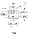
- Fig. 2 is a circuit block diagram of a printer according to this first embodiment of the present invention.
- this printer 1 comprises a CPU 2 (representing the microprocessor mentioned above) for controlling the overall printer operation, the RAM 3 as main work memory, a ROM 4 for storing control data and a control program, the EEPROM 5 for storing status data as described above, a print mechanism 6 for printing on a printing medium by means of a print head, the counter 7 for counting the passage of time and an interface 8 for connection to a host computer.
- a CPU 2 (representing the microprocessor mentioned above) for controlling the overall printer operation
- the RAM 3 main work memory
- ROM 4 for storing control data and a control program
- the EEPROM 5 for storing status data as described above
- a print mechanism 6 for printing on a printing medium by means of a print head
- the counter 7 for counting the passage of time
- an interface 8 for connection to a host computer.
- the CPU 2 loads program and control data from ROM 4 and status data from EEPROM 5 into RAM 3 and controls printer operation based on the loaded program and control data in RAM 3.
- the printer is initialized based on the loaded data.
- the printer (CPU 2) then waits for a command from the host.
- the printer 1 has various sensors, not shown in the figures, for monitoring the operating conditions of the printer.
- the status data in RAM 3 which is generated by and in response to these sensors, respectively, is sequentially updated, and in response to specific trigger events described in detail below it is copied and saved to specific memory areas in EEPROM 5.
- the status data saved to EEPROM 5 is loaded from EEPROM 5 into RAM 3 when the printer 1 is initialized or reset, and is thus used as the initial data for the printer control.
- the head cleaning time described above represents the time of the last head cleaning event.
- the CPU 2 uses this head cleaning time to determine the timing of the start of the next head cleaning event, and initiates head cleaning at that time.
- the printer 1 when a printer error occurs, causing the printer to stop operating in the middle of a print job, for example, the printer 1 is restored to the previous normal operating condition based on the location of the print head read from EEPROM 5 after the printer 1 is reset.
- the timing of saving data to the EEPROM 5 and the saving procedure itself as well as the copying from the EEPROM 5 to the RAM 3, are controlled by the CPU 2.
- the counter 7 measures the elapse of a predetermined saving period based on an internal clock circuit (not shown in the figures). Whenever data is saved to EEPROM 5, the CPU 2 re-starts counter 7 to count said saving period. When this predetermined period elapses (1 hour, for example), the counter 7 outputs a signal notifying the CPU 2 that the counted period has elapsed. In response to this signal the CPU 2 acts to save the above mentioned first set of data groups to EEPROM 5. It goes without saying that the counter 7 may also be implemented by the CPU 2.
- the CPU 2 also has a reset signal detection function 9 and a reset function 10.
- This reset signal detection function 9 detects when a reset signal has been received from the host computer. When a reset signal is detected, the CPU 2 issues a write command for saving at least part of the data in RAM 3 to EEPROM 5.
- the reset function 10 is a function for resetting the printer, an operation that includes copying all of the data in EEPROM 5 to RAM 3, returning various printer components (such as the print head) to respective initialization positions, and entering a standby state waiting for data from the host.
- the CPU 2 performs the reset function 10. This sequence ensures that data relating to the printer status before the reset are saved to EEPROM 5.
- FIG. 3 is an illustration of an example of the logical structure of the memory areas in EEPROM 5 and RAM 3 used for storing status data.
- the EEPROM 5 and RAM 3 (or part of them) are logically segmented into six memory areas A1 to A6. Each of the areas in EEPROM 5 corresponds to an area in RAM 3, enabling data to be copied in units of a memory area from RAM 3 to EEPROM 5 and vice versa.
- the status data are also divided into six data groups. These six data groups are each assigned to a respective one of the six memory areas. As a result, data storage is accomplished in units of data group, copying one or a plurality of data groups at a time.
- Each of memory areas A1 to A6 includes data area and a checksum area.
- the checksum of each copied data group is used for error detection.
- a data group is copied from a source memory area (in EEPROM 5 or RAM 3) to a destination memory area (in RAM 3 or EEPROM 5) the checksum is calculated based on the copied data group in the destination memory area and compared with the checksum stored for that data group in the source or destination memory area.
- Default (initialization) values for the status data are stored in ROM 4 or in another memory area (other than memory areas A1 to A6) of EEPROM 5 in Fig. 2. These default values are values suitable to assure normal printer operation. When the checksum comparison explained above reveals a data error for a data group, the status data stored in the related pair of memory areas of RAM 3 and EEPROM 5 are replaced with the default values. This makes it possible to minimize printer operating problems when an error occurs.
- Fig. 4 is a table showing the relationship between data groups A1 to A6 and the trigger events upon which the respective data groups are saved to EEPROM 5.
- One of the first steps in memory control according to the present invention is to select a plurality of "trigger events" at which certain data groups are saved to the respective memory areas. As shown in Fig.
- these trigger events include in the present embodiment: turning on power to the printer, lapse of the saving period (such as 1 hour), specific printer events (such as print head cleaning, ink cartridge and roll paper replacement, occurrence of a printer operating error), the moment when a counter for tracking specific control information indicates a change of that control information by a predetermined amount (e.g., the count value of a counter for tracking the accumulated drive count of a roll paper cutter reaches a specific value), and detection of a reset signal (including reset signals from the host and a reset signal generated when an abnormal voltage is detected).
- the status data are divided into six data groups according to the trigger events described above, and assigned to the six memory areas shown in Fig. 3.
- the following status data are included in the respective data groups (note that the data groups are given the same names A1 to A6 as the corresponding memory areas).
- Data Group/ Memory Area Status Data A1 time at which power to the printer is turned on A2 printed line count since the last print head cleaning event, and total printed line count since printer manufacture A3 time of the last print head cleaning event, and the cleaning level A4 cumulative drive count of the roll paper cutter A5 reset flag, time of the most recent trigger event, ink consumption counter A6 various complementary data (such as carriage travel distance)
- data group A1 i.e. the current time is saved to EEPROM 5
- data groups A2 and A5 are saved periodically with the saving period.
- data groups A2 to A5 are saved; and when a reset occurs, only data group A5 is saved.
- Data group A6 stored in memory area A6 is used, for example, to correct the printing position as a result of variations between specific mechanical components of the printer, and is written prior to shipping from the factory and when the printer is repaired. It will thus be obvious that not all data groups need to be saved at every trigger event shown in Fig. 4.
- first and the second set of data groups have been referred to above, it is to be noted that, as shown in Fig. 4, in the present embodiment there are three other sets, namely a third set including only data group A1, a fourth set of data groups A2, A4 and A5 and a fifth set of only data group A5.
- the data group A5 includes information that is, relative to information of other data groups, important for the printer control, and is therefore more frequently saved. Furthermore, a reset signal is also generated when a power failure or a voltage drop is detected, for example. The data group A5 is therefore saved in response to a rest signal while the other data groups are not saved.
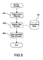
- a table 40 (see Fig. 5) corresponding to that shown in Fig. 4 is stored in a memory area of ROM 4 or another memory area of EEPROM 5 and is read when any of the trigger events stored in the table occurs.
- Fig. 5 is a flow chart of the saving process by which data is saved to EEPROM 5.
- This flow chart shows the procedure from when one of the trigger events shown in the table occurs until the data group(s) concerned is (are) copied from RAM 3 to EEPROM 5.
- the table 40 is read and used to determine the data group(s) to be saved to EEPROM 5 (step 402).
- the thus determined data group(s) is (are) then read out from RAM 3 and written to the corresponding area(s) in EEPROM 5 (step 403).
- step 403 As a result, only that data group(s) defined for being saved at a respective trigger event is indeed saved to EEPROM 5 when that trigger event occurs.
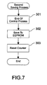
- Fig. 6 and Fig. 7 are flow charts illustrating saving processes in a printer 1 according to a preferred embodiment of the present invention.
- Fig. 6 shows the periodic saving process (first saving process)
- Fig. 7 shows the event-driven saving process (second saving process).
- data stored in EEPROM 5 is loaded into RAM 3 when the printer 1 is activated, and the counter 7 starts counting the saving period (step 201).
- data groups A2 and A5 (forming the first set of data groups) are saved to EEPROM 5 (step 203) as mentioned above. If this interval is 1 hour, for example, these data groups are saved at least once every hour.
- the counter 7 is reset and begins counting the next saving period (the first saving process enters a standby mode in step 204).
- the data of data groups A2 and A5 is written to EEPROM 5 every time the predetermined saving period elapses.
- control events include: print head cleaning, replacement of the ink cartridge or roll paper, and operating errors such as a rise in the print head temperature or disconnection of the carriage transportation belt.
- CPU 2 passes control to the second saving process shown in Fig. 7. More specifically, it is first detected when the control process, if any, related to the control event is completed (step 301), the control information (e.g., count values) that has been updated in RAM 3 by that control process is then saved to EEPROM 5 (step 302). As shown in Fig.
- the data group A3 is saved only in step 302 in Fig. 7.
- data groups A2 and A5 are saved to EEPROM 5 both periodically with the saving period (step 203 in Fig. 6), and together with data groups A3 and A4 when one of the specific control events occurs. Even though this may slightly increase the frequency of writing to the nonvolatile EEPROM, a drop in printer throughput is prevented because the counter 7 is reset in step 303.
- Fig. 8 is an illustration of the logical structure of memory area A5 in EEPROM 5 and RAM 3 according to a preferred embodiment of the invention.
- memory area A5 in EEPROM 5 is further divided into a plurality of subareas A5A to A5N.
- Each of these subareas A5A to A5N includes, in addition to a status data area, a sequence area for storing a sequence value and a checksum area.
- data group A5 is saved to EEPROM 5 it is written into a selected one of the subareas.
- the subareas are sequentially and cyclically selected.
- the sequence value is used to identify the subarea that holds the most recently saved data.
- data group A5 be specified in step 402.
- data group A5 is saved from RAM 3 to EEPROM 5 in step 403, it is written to the subarea next in sequence after the subarea last used. For example, if data group A5 was written to subarea A5A the last time step 403 was executed and data group A5 was specified, data group A5 is written to subarea A5B in the present step 403.
- a 2-byte area is allocated for the sequence value, enabling codes OO H to FF H to be stored, i.e., the sequence value can assume any value between 0 and 65536.
- the sequence value is increased (since the sequence value changes cyclically it could be decreased instead) and the updated value is written into the sequence area of the respective subarea. For example, if data was written to subarea A5A the last time step 403 was executed and a sequence value of 05 is stored in the sequence area of subarea A5A, a value of 06 is stored in the sequence area of subarea A5B in the present step 403.
- the sequence value that will be stored in the sequence area of a particular subarea will always be different from that that was written into the same sequence area the previous time. Therefore, the sequence value stored in the subarea that holds the most recently saved data, and the sequence value stored in the subarea next in sequence to that subarea will be discontinuous. This discontinuity allows to identify among the subareas that one that holds the most recently saved data as well as those preceding.
- the sequence values stored in subareas A5A to A5N are compared to find the above explained discontinuity, thereby to identify the subarea holding the most recent data and to load the most recent data into the memory area A5 of RAM 3. For example, if the values stored in the sequence areas of subareas A5A, A5B, and A5C are 05, 06, and F8, the status data stored in subarea A5B is the most recent one, and is therefore loaded into memory area A5 of RAM 3.
- the data group A5 is saved whenever a reset signal is detected, and is usually information that is important for the printer control. This information is also saved in response to other control events, so that the saving frequency for memory area A5 is greater than that of other memory areas.
- nonvolatile memory a flash memory or other type of nonvolatile memory can be alternatively used.
- the data stored in the nonvolatile memory are of course not limited to that described above. More specifically, data relating to any printer condition can be stored, or only a subset of the above-described status data can be stored. In addition to storing status data, the nonvolatile memory can be used to store other data, including font data and program data.
- the invention is also not limited to the trigger events described above. Furthermore, a checksum has been described for error detection, but it will be obvious that other error detection codes, including a parity check code, or even error detection and correction codes can be alternatively used.
Landscapes
- Engineering & Computer Science (AREA)
- General Engineering & Computer Science (AREA)
- Physics & Mathematics (AREA)
- General Physics & Mathematics (AREA)
- Theoretical Computer Science (AREA)
- Techniques For Improving Reliability Of Storages (AREA)
Claims (15)
- Imprimante comprenant :un moyen (5) formant mémoire non volatile ayant une pluralité de zones (A1-A6) de mémoire ;un moyen (3) formant mémoire volatile ayant une pluralité de zones (A1-A6) de mémoire, chaque zone de la pluralité de zones de mémoire de la mémoire volatile correspondant à l'une respective des zones de la pluralité de zones de mémoire de la mémoire non volatile ;un moyen (56) de contrôle pour détecter l'apparition d'un événement déclencheur prédéterminé indiquant une opération prédéterminée de l'imprimante, pour générer une première commande de sauvegarde en réponse à chaque événement déclencheur détecté ; etdes moyens (51, 52, 54) de sauvegarde comprenant un premier moyen (52) de lecture / écriture sensible à la première commande de sauvegarde pour sauvegarder un premier ensemble de données comprenant les données d'une ou plusieurs des zones (A1-A6) de mémoire de la mémoire (3) volatile dans les zones (A1-A6) correspondantes de mémoire de la mémoire (5) non volatile ;caractérisée en ce quele moyen de contrôle comprend un compteur (7) pour compter périodiquement une durée prédéterminée de sauvegarde, et un moyen pour générer une deuxième commande de sauvegarde en réponse au fait que le compteur a compté la durée prédéterminée de sauvegarde, etle moyen de sauvegarde comprend un deuxième moyen (51) de lecture / écriture sensible à la deuxième commande de sauvegarde pour sauvegarder un deuxième ensemble de données comprenant les données d'une ou plusieurs des zones (A1-A6) de mémoire de la mémoire (3) volatile dans les zones (A1-A6) correspondantes de mémoire de la mémoire (5) non volatile, le deuxième ensemble de données comprenant les données d'une ou plusieurs des zones de mémoire non incluses dans le premier ensemble.
- Imprimante selon la revendication 1, comprenant en outre un moyen d'initialisation pour remettre à zéro le compteur (7) en réponse à la sauvegarde effectuée par le deuxième moyen (51) de lecture / écriture.
- Imprimante selon la revendication 1 ou 2, dans laquelle chaque zone (A1-A6) de mémoire comprend une zone de données pour stocker les données représentant les conditions de fonctionnement de l'imprimante, et une zone de somme de contrôle pour stocker un code de détection d'erreur.
- Imprimante selon l'une quelconque des revendications 1 à 3, dans laquelle au moins une zone (A5) de la pluralité de zones (A1-A6) de mémoire de la mémoire (5) non volatile est divisée en une pluralité de zones (A5A - A5N) secondaires, chaque zone secondaire comprenant une zone de données pour stocker des données représentant les conditions de fonctionnement de l'imprimante et une zone de séquence pour stocker des données de séquence représentant la séquence d'utilisation des zones secondaires.
- Imprimante selon la revendication 4, dans laquelle chaque zone (A5A - A5N) secondaire comprend en outre une zone de somme de contrôle pour stocker un code de détection d'erreur.
- Procédé de commande pour sauvegarder des données d'une mémoire (3) volatile dans une mémoire (5) non volatile dans une imprimante (1), dans lequel le moyen (5) formant mémoire non volatile a une pluralité de zones (A1-A6) de mémoire et le moyen (3) formant mémoire volatile a une pluralité de zones (A1-A6) de mémoire, chaque zone de la pluralité de zones de mémoire de la mémoire volatile correspondant à l'une respective des zones de la pluralité de zones de mémoire de la mémoire non volatile, le procédé de commande comprenant les étapes consistant à :a) détecter l'apparition d'un événement déclencheur prédéterminé indiquant une opération prédéterminée de l'imprimante et générer une première commande de sauvegarde en réponse à chaque événement déclencheur détecté ;b) grouper toutes les données qui doivent être sauvegardées dans la mémoire non volatile dans un certain nombre de groupes de données, etc) attribuer chaque groupe de données à une paire respective de zones correspondantes de mémoire des mémoires (3, 5) volatile et non volatile, etd) sauvegarder, en réponse à la première commande de sauvegarde, un premier ensemble de données comprenant les données d'une ou plusieurs des zones de mémoire de la mémoire (3) volatile dans les zones (A1-A6) correspondantes de mémoire de la mémoire (5) non volatile ;caractérisé en ce que
l'étape a) comprend une mesure périodique d'une durée prédéterminée de sauvegarde et la génération d'une deuxième commande de sauvegarde chaque fois que la durée de sauvegarde est écoulée ; et
l'étape d) comprend une sauvegarde en réponse à la deuxième commande de sauvegarde, d'un deuxième ensemble de données comprenant les données d'un ou plusieurs des groupes de données des zones de mémoire de la mémoire (3) volatile dans les zones correspondantes de mémoire de la mémoire (5) non volatile, le deuxième ensemble de données comprenant les données d'un ou plusieurs groupes de données non inclus dans le premier ensemble. - Procédé de commande selon la revendication 6, dans lequel la mesure de la durée prédéterminée de sauvegarde redémarre en réponse à l'exécution de la deuxième commande de sauvegarde.
- Procédé de commande selon la revendication 6 ou 7, dans lequel l'étape a) génère la deuxième commande de sauvegarde en réponse à chaque événement déclencheur d'une pluralité d'événements déclencheurs prédéterminés indiquant chacun une opération différente de l'imprimante, les événements déclencheurs comprenant la détection d'un signal de réinitialisation provenant d'un ordinateur hôte auquel l'imprimante (1) est connectée, et l'imprimante est réinitialisée en réponse à ce signal de réinitialisation après l'étape d).
- Procédé de commande selon la revendication 8, dans lequel les événements déclencheurs comprennent la mise sous ou hors tension de l'imprimante.
- Procédé de commande selon la revendication 8 ou 9, dans lequel les événements déclencheurs comprennent le nettoyage de la tête d'impression.
- Procédé de commande selon l'une quelconque des revendications 6 à 10 pour sauvegarder des données dans une imprimante comme celle définie dans la revendication 3, le procédé de commande comprenant en outre l'étape consistant à :e) calculer un code de détection d'erreur sur la base des données d'un groupe de données, comparer le code calculé de détection d'erreur avec celui enregistré dans une zone associée de somme de contrôle et signaler une erreur de données si les codes de détection d'erreur comparés sont différents.
- Procédé de commande selon la revendication 11, dans lequel l'étape e) est exécutée pour détecter une erreur dans les données d'une zone (A1-A6) de mémoire lue dans la mémoire (5) non volatile pendant l'exécution de l'étape d).
- Procédé de commande selon la revendication 6, dans lequel l'étape e) est exécutée pour détecter une erreur dans un groupe de zones de données après que le groupe de données a été sauvegardé dans la mémoire (5) non volatile à l'étape d).
- Procédé de commande selon l'une quelconque des revendications 11 à 13, comprenant en outre une étape consistant à :f) écrire des données spécifiques d'initialisation dans la paire concernée de zones (A1-A6) correspondantes de mémoire dans les mémoires (3, 5) volatile et non volatile quand une erreur de données est signalée à l'étape e).
- Procédé de commande selon l'une quelconque des revendications 6 à 14 pour sauvegarder des données dans une imprimante comme celle définie dans la revendication 4, l'étape d) comprenant :d1) l'exploration des zones (A5A - A5N) secondaires de la mémoire (5) non volatile et la recherche d'une paire composée d'une première et d'une deuxième des deux zones secondaires successives pour lesquelles la différence absolue entre les valeurs représentées par les données respectives de séquence est supérieure à celle d'une valeur incrémentielle positive ou négative, identifiant ainsi la première zone secondaire comme celle parmi les zones secondaires de ladite au moins une zone (A5) de mémoire qui contient les données les plus récentes,d2) la lecture des données de séquence enregistrées dans la zone de séquence dans la première zone secondaire et l'ajout de la valeur incrémentielle aux données de séquence lues afin d'obtenir des données de séquence mises à jour, etd3) l'écriture du groupe (A5) de données correspondant à ladite au moins une zone (A5) de mémoire dans la zone de données et des données de séquence mises à jour dans la zone de séquence de la deuxième zone secondaire.
Applications Claiming Priority (2)
| Application Number | Priority Date | Filing Date | Title |
|---|---|---|---|
| JP13207298 | 1998-05-14 | ||
| JP13207298 | 1998-05-14 |
Publications (3)
| Publication Number | Publication Date |
|---|---|
| EP0957447A2 EP0957447A2 (fr) | 1999-11-17 |
| EP0957447A3 EP0957447A3 (fr) | 2000-10-18 |
| EP0957447B1 true EP0957447B1 (fr) | 2007-10-31 |
Family
ID=15072866
Family Applications (1)
| Application Number | Title | Priority Date | Filing Date |
|---|---|---|---|
| EP99109615A Expired - Lifetime EP0957447B1 (fr) | 1998-05-14 | 1999-05-14 | Méthode de controle de sauvegarde de données d'un mémoire volatile dans une mémoire non volatile dans une imprimante |
Country Status (3)
| Country | Link |
|---|---|
| US (1) | US6516440B1 (fr) |
| EP (1) | EP0957447B1 (fr) |
| DE (1) | DE69937424T2 (fr) |
Families Citing this family (21)
| Publication number | Priority date | Publication date | Assignee | Title |
|---|---|---|---|---|
| EP1187058A3 (fr) | 2000-08-30 | 2003-01-02 | Seiko Epson Corporation | Imprimante, support de stockage de données, interface, méthode de commande d'imprimante, et méthode de contrôle d'interface |
| US6694453B1 (en) * | 2000-11-14 | 2004-02-17 | Hewlett-Packard Development Company, L.P. | Apparatus and method to handle power supply failures for a peripheral device |
| JP2002254622A (ja) | 2001-02-28 | 2002-09-11 | Canon Inc | 記録装置及び記録システム |
| JP2003034060A (ja) * | 2001-07-23 | 2003-02-04 | Mitsumi Electric Co Ltd | プリンタ |
| US6825864B2 (en) * | 2001-11-26 | 2004-11-30 | Codonics, Inc. | Multi-media printer |
| JP4145185B2 (ja) * | 2002-04-16 | 2008-09-03 | 株式会社リコー | 画像形成装置及びネットワークシステム |
| EP1557648A4 (fr) * | 2002-10-27 | 2007-12-26 | Citizen Holdings Co Ltd | Systeme de dispositif electronique de mesure |
| EP2275918B1 (fr) * | 2004-08-27 | 2014-04-16 | Seiko Epson Corporation | Imprimante et méthode de commande d'imprimante |
| JP2006062266A (ja) * | 2004-08-27 | 2006-03-09 | Seiko Epson Corp | プリンタ及びプリンタの制御方法 |
| US7275881B2 (en) * | 2004-10-15 | 2007-10-02 | Sanford, L.P. | Control of dual printing mechanisms |
| US7647474B2 (en) * | 2005-09-27 | 2010-01-12 | Intel Corporation | Saving system context in the event of power loss |
| JP4462291B2 (ja) * | 2007-05-31 | 2010-05-12 | ブラザー工業株式会社 | 情報処理装置、情報処理プログラムおよび情報処理システム |
| JP4959630B2 (ja) * | 2008-05-23 | 2012-06-27 | 株式会社東芝 | データ記憶装置 |
| JP5386881B2 (ja) * | 2008-08-07 | 2014-01-15 | セイコーエプソン株式会社 | ラベル用紙の頭出し制御方法およびラベルプリンタ |
| JP4894884B2 (ja) * | 2009-05-11 | 2012-03-14 | コニカミノルタビジネステクノロジーズ株式会社 | 画像形成装置、画像形成装置の制御方法、及び画像形成装置の制御プログラム |
| JP5091940B2 (ja) * | 2009-12-28 | 2012-12-05 | 京セラドキュメントソリューションズ株式会社 | 画像形成装置および不揮発性メモリ書き込み方法 |
| JP5994692B2 (ja) * | 2013-03-15 | 2016-09-21 | ブラザー工業株式会社 | 中継サーバ及び通信装置 |
| US9684853B2 (en) * | 2014-04-15 | 2017-06-20 | Kyocera Document Solutions Inc. | Image forming apparatus that writes data from volatile memory to non-volatile memory |
| JP5982025B1 (ja) * | 2015-02-27 | 2016-08-31 | 京セラドキュメントソリューションズ株式会社 | 情報処理装置およびメモリー管理プログラム |
| JP6543122B2 (ja) * | 2015-07-17 | 2019-07-10 | キヤノン株式会社 | 情報処理装置と、前記情報処理装置による不揮発記憶装置の初期化方法、及びプログラム |
| JP2019061458A (ja) * | 2017-09-26 | 2019-04-18 | 京セラドキュメントソリューションズ株式会社 | 電子機器およびログアプリケーション |
Family Cites Families (8)
| Publication number | Priority date | Publication date | Assignee | Title |
|---|---|---|---|---|
| GB1545169A (en) * | 1977-09-22 | 1979-05-02 | Burroughs Corp | Data processor system including data-save controller for protection against loss of volatile memory information during power failure |
| JPH01304468A (ja) | 1988-06-02 | 1989-12-08 | Fujitsu Ltd | 画像印刷装置 |
| JPH0667986A (ja) | 1992-08-19 | 1994-03-11 | Casio Comput Co Ltd | 情報処理装置 |
| JPH0667987A (ja) | 1992-08-19 | 1994-03-11 | Casio Comput Co Ltd | 情報処理装置 |
| JPH06314217A (ja) | 1993-04-28 | 1994-11-08 | Tokyo Electric Co Ltd | 電子機器 |
| US5533190A (en) * | 1994-12-21 | 1996-07-02 | At&T Global Information Solutions Company | Method for maintaining parity-data consistency in a disk array |
| US6145068A (en) * | 1997-09-16 | 2000-11-07 | Phoenix Technologies Ltd. | Data transfer to a non-volatile storage medium |
| US6209088B1 (en) * | 1998-09-21 | 2001-03-27 | Microsoft Corporation | Computer hibernation implemented by a computer operating system |
-
1999
- 1999-05-14 DE DE69937424T patent/DE69937424T2/de not_active Expired - Lifetime
- 1999-05-14 EP EP99109615A patent/EP0957447B1/fr not_active Expired - Lifetime
- 1999-05-14 US US09/312,039 patent/US6516440B1/en not_active Expired - Lifetime
Also Published As
| Publication number | Publication date |
|---|---|
| DE69937424D1 (de) | 2007-12-13 |
| EP0957447A3 (fr) | 2000-10-18 |
| US6516440B1 (en) | 2003-02-04 |
| EP0957447A2 (fr) | 1999-11-17 |
| DE69937424T2 (de) | 2008-08-21 |
Similar Documents
| Publication | Publication Date | Title |
|---|---|---|
| EP0957447B1 (fr) | Méthode de controle de sauvegarde de données d'un mémoire volatile dans une mémoire non volatile dans une imprimante | |
| US7483163B2 (en) | Printing apparatus, data storage medium, interface device, printer control method, and interface control method | |
| KR100488269B1 (ko) | 인쇄장치,그제어방법및기록매체 | |
| EP2423853B1 (fr) | Appareil de traitement de stockage de données dans un appareil d'impression, appareil d'impression et procédé de traitement de stockage de données | |
| JP3826617B2 (ja) | 不揮発性メモリを備えたプリンタ、及びそのプリンタにおける不揮発性メモリへの書き込み制御方法 | |
| WO2017002658A1 (fr) | Appareil d'impression à jet d'encre | |
| JP2007021787A (ja) | メンテナンスカウンタ機能を備えた情報処理機器 | |
| JP2010204851A (ja) | 記憶装置及び情報処理装置 | |
| JP2000322326A (ja) | バックアップメモリの情報管理方法 | |
| JP3697785B2 (ja) | プリンタ装置 | |
| JP3823532B2 (ja) | プリンタにおける不揮発性メモリへの書き込み制御方法及びプリンタ | |
| JP2005035229A (ja) | プリンタ装置 | |
| JP2002046293A (ja) | インクジェットプリンタシステム | |
| JP3486205B2 (ja) | インクジェットヘッドを備えた電子卓上計算機 | |
| JP4106822B2 (ja) | 印刷装置、初期化方法、及び情報記録媒体 | |
| JP4136105B2 (ja) | 画像形成装置及びその制御方法 | |
| JP3823535B2 (ja) | プリンタにおける不揮発性メモリへの書き込み制御方法及びプリンタ | |
| JP7251081B2 (ja) | 情報処理装置およびプログラム | |
| JPH09123570A (ja) | プリンタ装置 | |
| JPH06105065A (ja) | 印字装置 | |
| JP4507601B2 (ja) | 画像形成装置 | |
| US20040103351A1 (en) | Redundant data storage in imaging devices | |
| JP2021022080A (ja) | メモリ制御装置 | |
| CN110908598A (zh) | 图像处理设备和信息处理方法 | |
| JP2004280740A (ja) | プリンタ装置の寿命情報管理方法 |
Legal Events
| Date | Code | Title | Description |
|---|---|---|---|
| PUAI | Public reference made under article 153(3) epc to a published international application that has entered the european phase |
Free format text: ORIGINAL CODE: 0009012 |
|
| AK | Designated contracting states |
Kind code of ref document: A2 Designated state(s): DE FR GB IT |
|
| AX | Request for extension of the european patent |
Free format text: AL;LT;LV;MK;RO;SI |
|
| PUAL | Search report despatched |
Free format text: ORIGINAL CODE: 0009013 |
|
| AK | Designated contracting states |
Kind code of ref document: A3 Designated state(s): AT BE CH CY DE DK ES FI FR GB GR IE IT LI LU MC NL PT SE |
|
| AX | Request for extension of the european patent |
Free format text: AL;LT;LV;MK;RO;SI |
|
| 17P | Request for examination filed |
Effective date: 20010323 |
|
| AKX | Designation fees paid |
Free format text: DE FR GB IT |
|
| 17Q | First examination report despatched |
Effective date: 20060721 |
|
| 17Q | First examination report despatched |
Effective date: 20060721 |
|
| RTI1 | Title (correction) |
Free format text: CONTROL METHOD OF SAVING DATA FROM VOLATILE TO NONVOLATILE MEMORY IN A PRINTER |
|
| GRAP | Despatch of communication of intention to grant a patent |
Free format text: ORIGINAL CODE: EPIDOSNIGR1 |
|
| 17Q | First examination report despatched |
Effective date: 20060721 |
|
| GRAS | Grant fee paid |
Free format text: ORIGINAL CODE: EPIDOSNIGR3 |
|
| GRAA | (expected) grant |
Free format text: ORIGINAL CODE: 0009210 |
|
| AK | Designated contracting states |
Kind code of ref document: B1 Designated state(s): DE FR GB IT |
|
| REG | Reference to a national code |
Ref country code: GB Ref legal event code: FG4D |
|
| REF | Corresponds to: |
Ref document number: 69937424 Country of ref document: DE Date of ref document: 20071213 Kind code of ref document: P |
|
| ET | Fr: translation filed | ||
| PLBE | No opposition filed within time limit |
Free format text: ORIGINAL CODE: 0009261 |
|
| STAA | Information on the status of an ep patent application or granted ep patent |
Free format text: STATUS: NO OPPOSITION FILED WITHIN TIME LIMIT |
|
| 26N | No opposition filed |
Effective date: 20080801 |
|
| REG | Reference to a national code |
Ref country code: FR Ref legal event code: PLFP Year of fee payment: 18 |
|
| PGFP | Annual fee paid to national office [announced via postgrant information from national office to epo] |
Ref country code: GB Payment date: 20160511 Year of fee payment: 18 Ref country code: DE Payment date: 20160510 Year of fee payment: 18 |
|
| PGFP | Annual fee paid to national office [announced via postgrant information from national office to epo] |
Ref country code: IT Payment date: 20160524 Year of fee payment: 18 Ref country code: FR Payment date: 20160412 Year of fee payment: 18 |
|
| REG | Reference to a national code |
Ref country code: DE Ref legal event code: R119 Ref document number: 69937424 Country of ref document: DE |
|
| GBPC | Gb: european patent ceased through non-payment of renewal fee |
Effective date: 20170514 |
|
| REG | Reference to a national code |
Ref country code: FR Ref legal event code: ST Effective date: 20180131 |
|
| PG25 | Lapsed in a contracting state [announced via postgrant information from national office to epo] |
Ref country code: DE Free format text: LAPSE BECAUSE OF NON-PAYMENT OF DUE FEES Effective date: 20171201 Ref country code: GB Free format text: LAPSE BECAUSE OF NON-PAYMENT OF DUE FEES Effective date: 20170514 |
|
| PG25 | Lapsed in a contracting state [announced via postgrant information from national office to epo] |
Ref country code: FR Free format text: LAPSE BECAUSE OF NON-PAYMENT OF DUE FEES Effective date: 20170531 Ref country code: IT Free format text: LAPSE BECAUSE OF NON-PAYMENT OF DUE FEES Effective date: 20170514 |