EP0956944A2 - Vorrichtung und Verfahren zum Biegen eines Behälterzuschnittes - Google Patents
Vorrichtung und Verfahren zum Biegen eines Behälterzuschnittes Download PDFInfo
- Publication number
- EP0956944A2 EP0956944A2 EP99100395A EP99100395A EP0956944A2 EP 0956944 A2 EP0956944 A2 EP 0956944A2 EP 99100395 A EP99100395 A EP 99100395A EP 99100395 A EP99100395 A EP 99100395A EP 0956944 A2 EP0956944 A2 EP 0956944A2
- Authority
- EP
- European Patent Office
- Prior art keywords
- box sheet
- tip
- sending
- hook
- fold
- Prior art date
- Legal status (The legal status is an assumption and is not a legal conclusion. Google has not performed a legal analysis and makes no representation as to the accuracy of the status listed.)
- Granted
Links
- 238000005452 bending Methods 0.000 title claims abstract description 25
- 238000000034 method Methods 0.000 claims description 2
- 238000001514 detection method Methods 0.000 description 2
- 238000010586 diagram Methods 0.000 description 1
- 238000012986 modification Methods 0.000 description 1
- 230000004048 modification Effects 0.000 description 1
Images



Classifications
-
- B—PERFORMING OPERATIONS; TRANSPORTING
- B31—MAKING ARTICLES OF PAPER, CARDBOARD OR MATERIAL WORKED IN A MANNER ANALOGOUS TO PAPER; WORKING PAPER, CARDBOARD OR MATERIAL WORKED IN A MANNER ANALOGOUS TO PAPER
- B31B—MAKING CONTAINERS OF PAPER, CARDBOARD OR MATERIAL WORKED IN A MANNER ANALOGOUS TO PAPER
- B31B50/00—Making rigid or semi-rigid containers, e.g. boxes or cartons
-
- B—PERFORMING OPERATIONS; TRANSPORTING
- B31—MAKING ARTICLES OF PAPER, CARDBOARD OR MATERIAL WORKED IN A MANNER ANALOGOUS TO PAPER; WORKING PAPER, CARDBOARD OR MATERIAL WORKED IN A MANNER ANALOGOUS TO PAPER
- B31B—MAKING CONTAINERS OF PAPER, CARDBOARD OR MATERIAL WORKED IN A MANNER ANALOGOUS TO PAPER
- B31B50/00—Making rigid or semi-rigid containers, e.g. boxes or cartons
- B31B50/26—Folding sheets, blanks or webs
- B31B50/52—Folding sheets, blanks or webs by reciprocating or oscillating members, e.g. fingers
- B31B50/54—Folding sheets, blanks or webs by reciprocating or oscillating members, e.g. fingers operating on moving material
-
- B—PERFORMING OPERATIONS; TRANSPORTING
- B31—MAKING ARTICLES OF PAPER, CARDBOARD OR MATERIAL WORKED IN A MANNER ANALOGOUS TO PAPER; WORKING PAPER, CARDBOARD OR MATERIAL WORKED IN A MANNER ANALOGOUS TO PAPER
- B31B—MAKING CONTAINERS OF PAPER, CARDBOARD OR MATERIAL WORKED IN A MANNER ANALOGOUS TO PAPER
- B31B50/00—Making rigid or semi-rigid containers, e.g. boxes or cartons
- B31B50/26—Folding sheets, blanks or webs
- B31B50/262—Folding sheets, blanks or webs involving folding, leading, or trailing flaps of blanks
Definitions
- the present invention relates to the field of box-making machines, Specifically, the present invention provides an apparatus for bending a sending box sheet or a sending box sheet blank along a fold formed at a predetermined position in the box sheet.
- an apparatus for bending a sending box sheet along a fold formed at a predetermined position in the box sheet comprises a hook, which can hang a tip of the sending box sheet, and a sensor which can detect said tip of the sending box sheet. Accordingly, said sensor can detect said tip of the sending box sheet, and said hook can bend the sending box sheet along a first fold by holding a tip of the sending box sheet.
- a hook 5 is provided in a typical device for bending a sending box sheet along a fold.
- the hook 5 is pressed by a spring for an opposite direction (left direction of Fig. 8(a)) of a sending direction of a box sheet 1 and can move the sending direction (right direction of Fig. 8 (a)) of the box sheet 1.
- a tip 5a of the hook 5 is positioned on a sending route of the box sheet. Therefore, when the box sheet 1 is sent, the tip 5a of the hook 5 holds the tip 1a of the sending box sheet 1.
- the hook 5 moves in the sending direction of the sending box sheet 1. Then, as shown in Fig. 8(b), the box sheet 1 is bent along a first fold by a force of the spring. The box sheet is further sent, as shown in Fig. 8(c), and because the tip 5a of the hook 5 is left of the tip 1a of the box sheet 1, the hook 5 is restored by force of the restitution of the spring, and then the bending box sheet 1 is sent frontwards.
- the typical device for bending a sending box sheet along a fold being thus described, it is possible to bend the box sheet automatically during the process of sending the box sheet.
- the tip of the hook is on a sending route of the box sheet, when the hook is restored, the tip of the hook hits on a face of the sending box sheet, thereby making a noise.
- the noise increases.
- An objection of the present invention is to overcome the above-described problems and to provide an apparatus for bending a box sheet along a fold formed at a predetermined position in the box sheet comprising: a hook which can hang a tip of the sending box sheet; a sensor which can detect said tip of the sending box sheet; and a lifting means which can lift a part between said tip and a first fold of the sending box sheet; wherein a tip of said hook is positioned above a sending route of the box sheet; and wherein said sensor detects said tip of the sending box sheet, and said lift means can lift said part between the tip and the most fore fold of the sending box sheet up to said position of said hook.
- the tip of the hook is positioned above a sending route of the box sheet, when the hook is restored, the tip of the hook does not hit on the face of the sending box sheet, and therefore a noise is not made.
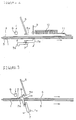
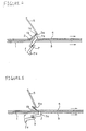
- Fig. 1 and 2 show an apparatus for bending a box sheet according to the present invention.
- the apparatus for bending a box sheet comprises two pairs of belts 3, 4 which can send the box sheet 1, a pair of hooks 5, a sensor 6 which can detect a tip 1a of the sending box sheet 1, and a lifting arm 7 which can lift a part 1b between the tip 1a and a first fold 2 of the sending box sheet up.
- Hook 5 is provided and is pressed by a spring (not pictured) from an opposite direction (left direction of Fig. 1 and 2) of the sending direction of the box sheet 1 and for moving the sending direction (right direction of Fig. 1 and 2) of the box sheet 1.
- a tip 5a of the hook 5 is bent for the opposite direction of the sending direction of the box sheet 1 and therefore can hold the tip 1a of the sending box sheet 1.
- the tip 5a of the hook 5 is positioned above a sending route of the box sheet 1, which is sending between belts 3 and 4.
- the lifting arm 7 comprises a pair of arms shaped in a letter of "L". Each of the arms is combined back to back.
- the lifting arm 7 can rotate so as to move the tip 7a of the lifting arm 7 at same speed and direction as the sending box sheet 1, when the tip 7a of the lifting arm 7 is positioned at the most upper part.
- the lifting arm 7 is set up below the belts 3, 4 so as to lift the part 1b between the tip 1a and a first fold 2 of the sending box sheet at the time when each tip 7a is nearly positioned at the most upper part.
- the lifting arm 7 is connected to a controlled device, 8, which can control the lifting arm 7.
- the sensor 6 is provided so as to be above the belts 3, 4 and to be in the same position as the lowest reaches of the tip 7a of the lifting arm 7. As shown in Fig. 7, the sensor 7 is connected to the controlled device 8. When the sensor 6 detects the tip 1a of the sending box sheet 1, the sensor 6 sends an information concerning the detection of the tip 1a of the sending sheet 1 to the controlled device 8. When the controlled device 8 receives the information, the controlled device 8 makes the lifting arm 7 rotate from a horizontal position of the lifting arm 7.
- a roller 9, a brush 10 and a guided rail 11 are provided above the belts 3, 4 and at the upper reaches of the hook 5.
- a space between the belt 3 and roller 9, brush 10 and a guided rail 11, is shorter than the part 1b between the tip 1a and a first fold 2 of the sending box sheet. Therefore, the box sheet 1 is sent with bending by passing through this roller 9, brush 10 and guided rail 11.
- the box sheet 1 is sent one after another by operating the belts 3, 4.
- the sensor 6 detects the tip 1a of the box sheet 1, and then sends the information concerning the detection of the tip 1a of the sending sheet 1 to the controlled device 8.
- the controlled device 8 accepts the information, the lifting arm 7 begins to rotate.
- the lifting arm 7 begins to rotate, as shown in Fig.
- the tip 1a of the box sheet 1 is held by the tip 5a of the hook 5.
- the hook 5 moves at the sending direction of the box sheet 1.
- the box sheet 1 is bent along the fold 2.
- the tip 5a of the hook 5 is left of the tip 1a of the box sheet 1, and the hook 5 is restored by a restitution force of the spring. Then, the bending box sheet 1 is sent to the roller 9, brush 10 and guided rail 11.
- Chart 1 Sending Speed 50m/m 100m/m 150m/m
- the Apparatus for Bending the Box Sheet which is sending the box sheet 62db 65db 70db
- the Apparatus for Bending the Box Sheet according to 68db 74db 79db the present invention The Typical Apparatus for Bending the Box Sheet 76db 80db 83db
- the part 1b between the tip 1a and a first fold 2 of the sending box sheet is lifted up by rotating of the lifting arm 7, the part 1b may be lifted up by a cylinder.
- the lifting arm 7 is electrically controlled, it may be mechanically controlled.
Landscapes
- Making Paper Articles (AREA)
- Folding Of Thin Sheet-Like Materials, Special Discharging Devices, And Others (AREA)
Applications Claiming Priority (2)
| Application Number | Priority Date | Filing Date | Title |
|---|---|---|---|
| JP14666298 | 1998-05-13 | ||
| JP10146662A JP2941783B1 (ja) | 1998-05-13 | 1998-05-13 | ブランク折曲装置 |
Publications (3)
| Publication Number | Publication Date |
|---|---|
| EP0956944A2 true EP0956944A2 (de) | 1999-11-17 |
| EP0956944A3 EP0956944A3 (de) | 2000-04-26 |
| EP0956944B1 EP0956944B1 (de) | 2004-07-28 |
Family
ID=15412796
Family Applications (1)
| Application Number | Title | Priority Date | Filing Date |
|---|---|---|---|
| EP99100395A Expired - Lifetime EP0956944B1 (de) | 1998-05-13 | 1999-01-18 | Vorrichtung und Verfahren zum Biegen eines Behälterzuschnittes |
Country Status (4)
| Country | Link |
|---|---|
| US (1) | US6228010B1 (de) |
| EP (1) | EP0956944B1 (de) |
| JP (1) | JP2941783B1 (de) |
| DE (1) | DE69918895T2 (de) |
Cited By (1)
| Publication number | Priority date | Publication date | Assignee | Title |
|---|---|---|---|---|
| WO2010086081A1 (fr) * | 2009-01-28 | 2010-08-05 | Bobst Sa | Dispositif et procede de pliage pour machine plieuse-colleuse |
Families Citing this family (7)
| Publication number | Priority date | Publication date | Assignee | Title |
|---|---|---|---|---|
| US20040180770A1 (en) * | 2003-03-11 | 2004-09-16 | Cook Matthew R. | Machine for and method of securing a lining bag at precise locations on the inner surface of a container blank |
| EP1637316B1 (de) * | 2004-09-20 | 2007-01-03 | Bobst Sa | Vorrichtung zum Falten der Laschen eines Schachtelzuschnittes |
| EP1685950B1 (de) * | 2005-01-28 | 2008-08-13 | Bobst S.A. | Halterungsvorrichtung für die Seitenlaschen von Schachtelzuschnitten in einer Falt- und Zusammenklebmaschine |
| TWI469865B (zh) * | 2008-09-30 | 2015-01-21 | Bobst Sa | 用於輸送及折疊坯料之裝置 |
| ES2384067B1 (es) * | 2009-08-04 | 2013-05-07 | Volpak, S.A.U. | Procedimiento y máquina para fabricar en continuo envases de material flexible. |
| JP6137993B2 (ja) * | 2013-08-26 | 2017-05-31 | 株式会社日本紙工機械グループ | ブランク折曲装置及びブランク折曲方法 |
| CN116141756B (zh) * | 2022-09-13 | 2025-05-16 | 潍坊瀚创自动化设备有限公司 | 一种粘鼠板生产用折边机 |
Family Cites Families (15)
| Publication number | Priority date | Publication date | Assignee | Title |
|---|---|---|---|---|
| US2899872A (en) * | 1959-08-18 | labombarde | ||
| DE1125753B (de) | 1960-04-23 | 1962-03-15 | Jagenberg Werke Ag | Faltschachtelklebemaschine mit selbsttaetiger Bodenverschliesseinrichtung |
| DE1169271B (de) | 1961-09-27 | 1964-04-30 | Bobst & Sohn A G J | Vorrichtung zum Falten der vorderen Laschen eines Pappewerkstueckes, insbesondere ineiner Falt- und Klebemaschine |
| CH383140A (fr) * | 1963-04-23 | 1964-10-15 | Bobst Fils Sa J | Crochet servant à rabattre une patte dans une plieuse-colleuse travaillant des pièces de carton |
| DE1207778B (de) | 1964-05-27 | 1965-12-23 | Jagenberg Werke Ag | Vorrichtung zum Aufrichten der Bodenteile an Faltschachtelzuschnitten |
| DE1211474B (de) * | 1964-12-15 | 1966-02-24 | Jagenberg Werke Ag | Vorrichtung zum Aufrichten der Bodenteile an Faltschachtelzuschnitten |
| JPS52144918A (en) | 1976-05-28 | 1977-12-02 | Toshiba Corp | Picture enlargement unit |
| JPS53120993A (en) | 1977-03-29 | 1978-10-21 | Omori Machinery | Packing method and apparatus |
| US4432745A (en) * | 1982-05-06 | 1984-02-21 | Paxall, Inc. | Trailing edge folder |
| US4539002A (en) * | 1982-07-23 | 1985-09-03 | Post Machinery Company, Inc. | Control apparatus for trailing edge folder in carton folding machine |
| JPS6094936A (ja) | 1983-10-29 | 1985-05-28 | Kanebo Ltd | パラメトキシ桂皮酸多価金属塩 |
| US4629445A (en) | 1984-08-14 | 1986-12-16 | Tanabe Machinery Co., Ltd. | Apparatus for folding rear portion of case blank |
| GB2165042B (en) | 1984-10-01 | 1987-12-31 | Tanabe Machinery | Device for detecting the position of a case blank in a case making machine |
| US5232428A (en) * | 1992-06-17 | 1993-08-03 | Oetlinger Tool Engineering Co., Inc. | Carton blank support tool for a folder gluer machine |
| US5685822A (en) * | 1996-08-08 | 1997-11-11 | Vision-Sciences, Inc. | Endoscope with sheath retaining device |
-
1998
- 1998-05-13 JP JP10146662A patent/JP2941783B1/ja not_active Expired - Fee Related
- 1998-12-02 US US09/203,703 patent/US6228010B1/en not_active Expired - Lifetime
-
1999
- 1999-01-18 EP EP99100395A patent/EP0956944B1/de not_active Expired - Lifetime
- 1999-01-18 DE DE69918895T patent/DE69918895T2/de not_active Expired - Lifetime
Cited By (3)
| Publication number | Priority date | Publication date | Assignee | Title |
|---|---|---|---|---|
| WO2010086081A1 (fr) * | 2009-01-28 | 2010-08-05 | Bobst Sa | Dispositif et procede de pliage pour machine plieuse-colleuse |
| CN102341231A (zh) * | 2009-01-28 | 2012-02-01 | 鲍勃斯脱股份有限公司 | 用于折叠粘合机的折叠装置及方法 |
| CN102341231B (zh) * | 2009-01-28 | 2014-12-24 | 鲍勃斯脱股份有限公司 | 用于折叠粘合机的折叠装置及方法 |
Also Published As
| Publication number | Publication date |
|---|---|
| US6228010B1 (en) | 2001-05-08 |
| EP0956944B1 (de) | 2004-07-28 |
| JP2941783B1 (ja) | 1999-08-30 |
| DE69918895T2 (de) | 2005-07-28 |
| EP0956944A3 (de) | 2000-04-26 |
| JPH11320711A (ja) | 1999-11-24 |
| DE69918895D1 (de) | 2004-09-02 |
Similar Documents
| Publication | Publication Date | Title |
|---|---|---|
| US11958447B2 (en) | Battery swapping system with quick swapping support | |
| US8321051B2 (en) | Workpiece pickup apparatus and workpiece pickup method | |
| US4958824A (en) | Automatic strip and sheet loader system | |
| EP0956944B1 (de) | Vorrichtung und Verfahren zum Biegen eines Behälterzuschnittes | |
| ITBO20010289A1 (it) | Metodo e dispositivo di alimentazione di bobine ad una macchina operatrice | |
| JP2834724B2 (ja) | 枚葉紙給紙装置 | |
| US5570514A (en) | Device and method for measuring crimp height | |
| GB2192594A (en) | Positioning a vehicle body for working thereon | |
| KR100917470B1 (ko) | 슬라브 무게 중심 측정장치 및 방법 | |
| CN101678424A (zh) | 用于滚圆板材段的方法和装置 | |
| JPH06305600A (ja) | パイル高さを周期的に触知する触知装置 | |
| ITTO940334A1 (it) | Dispositivo per il rilevamento dei bordi di articoli di spessore ridot to e sua applicazione in un'apparecchiatura di presa di tali articoli. | |
| CN208500771U (zh) | 一种支撑物布放装置 | |
| JPH11189391A (ja) | コイル搬送用吊具及びその使用方法 | |
| CN211029876U (zh) | 一种测试机架和测试设备 | |
| CN113687439A (zh) | 空调外机标签检测方法及装置 | |
| CN108819495A (zh) | 一种玻璃加工过程产品管理方法、系统及使用方法 | |
| CN213544687U (zh) | 天线产品自动检测装置 | |
| CN213812051U (zh) | 一种汽车空调压缩机的定盘检测装置 | |
| JP3192773B2 (ja) | 部品装着装置 | |
| KR101585068B1 (ko) | Fpd 셀 검사장치의 점등 유닛 블록 이동 제어방법 | |
| CN115057234B (zh) | 防空抓的玻璃安装设备及其防空抓方法 | |
| DK178007B1 (en) | Apparatus and method for rolling a carpet or a rug | |
| CN217293999U (zh) | 在线追随式无定向打码应用系统 | |
| JPH0655330B2 (ja) | ストレッチャレベラ |
Legal Events
| Date | Code | Title | Description |
|---|---|---|---|
| PUAI | Public reference made under article 153(3) epc to a published international application that has entered the european phase |
Free format text: ORIGINAL CODE: 0009012 |
|
| AK | Designated contracting states |
Kind code of ref document: A2 Designated state(s): CH DE FR GB IT LI |
|
| AX | Request for extension of the european patent |
Free format text: AL;LT;LV;MK;RO;SI |
|
| PUAL | Search report despatched |
Free format text: ORIGINAL CODE: 0009013 |
|
| AK | Designated contracting states |
Kind code of ref document: A3 Designated state(s): AT BE CH CY DE DK ES FI FR GB GR IE IT LI LU MC NL PT SE |
|
| AX | Request for extension of the european patent |
Free format text: AL;LT;LV;MK;RO;SI |
|
| 17P | Request for examination filed |
Effective date: 20000602 |
|
| AKX | Designation fees paid |
Free format text: CH DE FR GB IT LI |
|
| 17Q | First examination report despatched |
Effective date: 20020405 |
|
| RTI1 | Title (correction) |
Free format text: BOX SHEET BENDING APPARATUS AND METHOD |
|
| GRAP | Despatch of communication of intention to grant a patent |
Free format text: ORIGINAL CODE: EPIDOSNIGR1 |
|
| GRAS | Grant fee paid |
Free format text: ORIGINAL CODE: EPIDOSNIGR3 |
|
| GRAA | (expected) grant |
Free format text: ORIGINAL CODE: 0009210 |
|
| AK | Designated contracting states |
Kind code of ref document: B1 Designated state(s): CH DE FR GB IT LI |
|
| PG25 | Lapsed in a contracting state [announced via postgrant information from national office to epo] |
Ref country code: IT Free format text: LAPSE BECAUSE OF FAILURE TO SUBMIT A TRANSLATION OF THE DESCRIPTION OR TO PAY THE FEE WITHIN THE PRESCRIBED TIME-LIMIT;WARNING: LAPSES OF ITALIAN PATENTS WITH EFFECTIVE DATE BEFORE 2007 MAY HAVE OCCURRED AT ANY TIME BEFORE 2007. THE CORRECT EFFECTIVE DATE MAY BE DIFFERENT FROM THE ONE RECORDED. Effective date: 20040728 Ref country code: FR Free format text: LAPSE BECAUSE OF FAILURE TO SUBMIT A TRANSLATION OF THE DESCRIPTION OR TO PAY THE FEE WITHIN THE PRESCRIBED TIME-LIMIT Effective date: 20040728 |
|
| REG | Reference to a national code |
Ref country code: GB Ref legal event code: FG4D |
|
| REG | Reference to a national code |
Ref country code: CH Ref legal event code: EP |
|
| REF | Corresponds to: |
Ref document number: 69918895 Country of ref document: DE Date of ref document: 20040902 Kind code of ref document: P |
|
| REG | Reference to a national code |
Ref country code: CH Ref legal event code: NV Representative=s name: BOVARD AG PATENTANWAELTE |
|
| PLBE | No opposition filed within time limit |
Free format text: ORIGINAL CODE: 0009261 |
|
| STAA | Information on the status of an ep patent application or granted ep patent |
Free format text: STATUS: NO OPPOSITION FILED WITHIN TIME LIMIT |
|
| 26N | No opposition filed |
Effective date: 20050429 |
|
| EN | Fr: translation not filed | ||
| REG | Reference to a national code |
Ref country code: CH Ref legal event code: PUE Owner name: TANABE INTERNATIONAL CO., LTD. Free format text: TANABE MACHINERY CO., LTD.#14-13- HIGASHIUENO 1-CHOME TAITO-KU#TOKYO 110-0015 (JP) -TRANSFER TO- TANABE INTERNATIONAL CO., LTD.#2-2, MARUNOUCHI 2-CHOME CHIYODA-KU#TOKYO 100-0005 (JP) Ref country code: CH Ref legal event code: PFA Owner name: TANABE MACHINERY CO.; JP Free format text: TANABE MACHINERY CO., LTD.; 24-3, MISUJI 2-CHOME, TAITO-KU; TOKYO (JP) -TRANSFER TO- TANABE MACHINERY CO., LTD.; 14-13- HIGASHIUENO 1-CHOME TAITO-KU; TOKYO 110-0015 (JP) |
|
| REG | Reference to a national code |
Ref country code: GB Ref legal event code: 732E |
|
| REG | Reference to a national code |
Ref country code: CH Ref legal event code: PFA Owner name: TANABE INTERNATIONAL CO., LTD. Free format text: TANABE INTERNATIONAL CO., LTD.#2-2, MARUNOUCHI 2-CHOME CHIYODA-KU#TOKYO 100-0005 (JP) -TRANSFER TO- TANABE INTERNATIONAL CO., LTD.#2-2, MARUNOUCHI 2-CHOME CHIYODA-KU#TOKYO 100-0005 (JP) |
|
| PGFP | Annual fee paid to national office [announced via postgrant information from national office to epo] |
Ref country code: DE Payment date: 20160229 Year of fee payment: 18 Ref country code: CH Payment date: 20160128 Year of fee payment: 18 |
|
| PGFP | Annual fee paid to national office [announced via postgrant information from national office to epo] |
Ref country code: GB Payment date: 20160128 Year of fee payment: 18 |
|
| REG | Reference to a national code |
Ref country code: DE Ref legal event code: R079 Ref document number: 69918895 Country of ref document: DE Free format text: PREVIOUS MAIN CLASS: B31B0001540000 Ipc: B31B0050540000 |
|
| REG | Reference to a national code |
Ref country code: DE Ref legal event code: R119 Ref document number: 69918895 Country of ref document: DE |
|
| REG | Reference to a national code |
Ref country code: CH Ref legal event code: PL |
|
| GBPC | Gb: european patent ceased through non-payment of renewal fee |
Effective date: 20170118 |
|
| PG25 | Lapsed in a contracting state [announced via postgrant information from national office to epo] |
Ref country code: LI Free format text: LAPSE BECAUSE OF NON-PAYMENT OF DUE FEES Effective date: 20170131 Ref country code: CH Free format text: LAPSE BECAUSE OF NON-PAYMENT OF DUE FEES Effective date: 20170131 |
|
| PG25 | Lapsed in a contracting state [announced via postgrant information from national office to epo] |
Ref country code: DE Free format text: LAPSE BECAUSE OF NON-PAYMENT OF DUE FEES Effective date: 20170801 Ref country code: GB Free format text: LAPSE BECAUSE OF NON-PAYMENT OF DUE FEES Effective date: 20170118 |