EP0956847A2 - Sitzvorrichtung zum Einsetzen in eine Dusch- oder Badewanne - Google Patents
Sitzvorrichtung zum Einsetzen in eine Dusch- oder Badewanne Download PDFInfo
- Publication number
- EP0956847A2 EP0956847A2 EP99107138A EP99107138A EP0956847A2 EP 0956847 A2 EP0956847 A2 EP 0956847A2 EP 99107138 A EP99107138 A EP 99107138A EP 99107138 A EP99107138 A EP 99107138A EP 0956847 A2 EP0956847 A2 EP 0956847A2
- Authority
- EP
- European Patent Office
- Prior art keywords
- seat
- elements
- column
- bathtub
- shower
- Prior art date
- Legal status (The legal status is an assumption and is not a legal conclusion. Google has not performed a legal analysis and makes no representation as to the accuracy of the status listed.)
- Withdrawn
Links
- 238000003780 insertion Methods 0.000 claims abstract description 3
- 230000037431 insertion Effects 0.000 claims abstract description 3
- 238000005452 bending Methods 0.000 claims description 2
- XLYOFNOQVPJJNP-UHFFFAOYSA-N water Substances O XLYOFNOQVPJJNP-UHFFFAOYSA-N 0.000 description 2
- 230000005540 biological transmission Effects 0.000 description 1
- 238000010276 construction Methods 0.000 description 1
Images


Classifications
-
- A—HUMAN NECESSITIES
- A61—MEDICAL OR VETERINARY SCIENCE; HYGIENE
- A61G—TRANSPORT, PERSONAL CONVEYANCES, OR ACCOMMODATION SPECIALLY ADAPTED FOR PATIENTS OR DISABLED PERSONS; OPERATING TABLES OR CHAIRS; CHAIRS FOR DENTISTRY; FUNERAL DEVICES
- A61G7/00—Beds specially adapted for nursing; Devices for lifting patients or disabled persons
- A61G7/10—Devices for lifting patients or disabled persons, e.g. special adaptations of hoists thereto
- A61G7/1001—Devices for lifting patients or disabled persons, e.g. special adaptations of hoists thereto specially adapted for specific applications
- A61G7/1003—Devices for lifting patients or disabled persons, e.g. special adaptations of hoists thereto specially adapted for specific applications mounted on or in combination with a bath-tub
-
- A—HUMAN NECESSITIES
- A61—MEDICAL OR VETERINARY SCIENCE; HYGIENE
- A61G—TRANSPORT, PERSONAL CONVEYANCES, OR ACCOMMODATION SPECIALLY ADAPTED FOR PATIENTS OR DISABLED PERSONS; OPERATING TABLES OR CHAIRS; CHAIRS FOR DENTISTRY; FUNERAL DEVICES
- A61G7/00—Beds specially adapted for nursing; Devices for lifting patients or disabled persons
- A61G7/10—Devices for lifting patients or disabled persons, e.g. special adaptations of hoists thereto
- A61G7/1013—Lifting of patients by
- A61G7/1019—Vertical extending columns or mechanisms
-
- A—HUMAN NECESSITIES
- A61—MEDICAL OR VETERINARY SCIENCE; HYGIENE
- A61G—TRANSPORT, PERSONAL CONVEYANCES, OR ACCOMMODATION SPECIALLY ADAPTED FOR PATIENTS OR DISABLED PERSONS; OPERATING TABLES OR CHAIRS; CHAIRS FOR DENTISTRY; FUNERAL DEVICES
- A61G7/00—Beds specially adapted for nursing; Devices for lifting patients or disabled persons
- A61G7/10—Devices for lifting patients or disabled persons, e.g. special adaptations of hoists thereto
- A61G7/1049—Attachment, suspending or supporting means for patients
- A61G7/1059—Seats
-
- B—PERFORMING OPERATIONS; TRANSPORTING
- B65—CONVEYING; PACKING; STORING; HANDLING THIN OR FILAMENTARY MATERIAL
- B65G—TRANSPORT OR STORAGE DEVICES, e.g. CONVEYORS FOR LOADING OR TIPPING, SHOP CONVEYOR SYSTEMS OR PNEUMATIC TUBE CONVEYORS
- B65G69/00—Auxiliary measures taken, or devices used, in connection with loading or unloading
- B65G69/22—Horizontal loading or unloading platforms
- B65G69/24—Horizontal loading or unloading platforms having platform level adjusting means
-
- B—PERFORMING OPERATIONS; TRANSPORTING
- B66—HOISTING; LIFTING; HAULING
- B66F—HOISTING, LIFTING, HAULING OR PUSHING, NOT OTHERWISE PROVIDED FOR, e.g. DEVICES WHICH APPLY A LIFTING OR PUSHING FORCE DIRECTLY TO THE SURFACE OF A LOAD
- B66F3/00—Devices, e.g. jacks, adapted for uninterrupted lifting of loads
- B66F3/08—Devices, e.g. jacks, adapted for uninterrupted lifting of loads screw operated
- B66F3/10—Devices, e.g. jacks, adapted for uninterrupted lifting of loads screw operated with telescopic sleeves
-
- B—PERFORMING OPERATIONS; TRANSPORTING
- B66—HOISTING; LIFTING; HAULING
- B66F—HOISTING, LIFTING, HAULING OR PUSHING, NOT OTHERWISE PROVIDED FOR, e.g. DEVICES WHICH APPLY A LIFTING OR PUSHING FORCE DIRECTLY TO THE SURFACE OF A LOAD
- B66F3/00—Devices, e.g. jacks, adapted for uninterrupted lifting of loads
- B66F3/08—Devices, e.g. jacks, adapted for uninterrupted lifting of loads screw operated
- B66F3/20—Devices, e.g. jacks, adapted for uninterrupted lifting of loads screw operated actuated through multiple or change-speed gearings
-
- B—PERFORMING OPERATIONS; TRANSPORTING
- B66—HOISTING; LIFTING; HAULING
- B66F—HOISTING, LIFTING, HAULING OR PUSHING, NOT OTHERWISE PROVIDED FOR, e.g. DEVICES WHICH APPLY A LIFTING OR PUSHING FORCE DIRECTLY TO THE SURFACE OF A LOAD
- B66F7/00—Lifting frames, e.g. for lifting vehicles; Platform lifts
- B66F7/10—Lifting frames, e.g. for lifting vehicles; Platform lifts with platforms supported directly by jacks
- B66F7/12—Lifting frames, e.g. for lifting vehicles; Platform lifts with platforms supported directly by jacks by mechanical jacks
- B66F7/14—Lifting frames, e.g. for lifting vehicles; Platform lifts with platforms supported directly by jacks by mechanical jacks screw operated
-
- A—HUMAN NECESSITIES
- A61—MEDICAL OR VETERINARY SCIENCE; HYGIENE
- A61G—TRANSPORT, PERSONAL CONVEYANCES, OR ACCOMMODATION SPECIALLY ADAPTED FOR PATIENTS OR DISABLED PERSONS; OPERATING TABLES OR CHAIRS; CHAIRS FOR DENTISTRY; FUNERAL DEVICES
- A61G7/00—Beds specially adapted for nursing; Devices for lifting patients or disabled persons
- A61G7/05—Parts, details or accessories of beds
- A61G7/065—Rests specially adapted therefor
- A61G7/07—Rests specially adapted therefor for the head or torso, e.g. special back-rests
Definitions
- the invention relates to a device for insertion into a bathtub or the like as entry and exit aid.
- Such devices are helpful for the elderly or frail or indispensable. They enable safe and convenient entry and exit Get off in a bathtub, tub or the like.
- the basic construction always has a seat plate.
- the seat plate is in generally carried by a scissor frame, the scissor lever are adjustable and thus cause a change in the height of the seat plate.
- the drive can be electric or pneumatic or in the exploitation of the Water pressure of the municipal water network exist.
- Such a device has become known from DE 44 37 515 A1.
- This has a plurality of telescopic cylinders that can be extended and retracted.
- the lower end of the telescopic column is supported - indirectly or immediately - from the bottom of the tub, and the top end to the seat.
- the invention has for its object a seat device of the aforementioned Art to design such that the seat is continuously raised and lowered, and that the height once set remains unchanged regardless of the load on the seat remains.
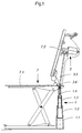
- a chair 7 can be seen in the embodiment according to FIG. 1 is a chair that is used in the rehabilitation industry as a "bath lift" is referred to and is used in a bathtub or the like to be used so that it can be used by the disabled or by the elderly can be used as an entry and exit aid.
- This bath lift has one Seat 7.1 and a backrest 7.2.
- the seat is by means of a column 1 according to the invention can be moved up and down.
- a drive 3 transmits Torque to the top via a shaft 3.5 with universal joint 3.6 Element 1.4 of the column.
- Pillar 1 also has other elements, namely elements 1.1, 1.2, 1.3. As you can see, the seat 7.1 rests on a pair of scissors.
- FIG. 2 differs from that according to FIG Figure 1 in the following: It has no scissors frame. Instead, the Seat 7.1 on four telescopic columns, of which only the one in this side view Columns 1 and 10 can be seen. All other elements are the same as for the embodiment according to FIG. 1.
- the column 1 shown in FIG. 3 is made up of several cylindrical elements 1.1 built up to 1.4. As you can see, elements 1.2, 1.3 and 1.4 are included Provided with external thread. The elements 1.1, 1.2, 1.3 also point in their an internal thread in the upper areas. All threads are in present case trapezoidal thread. However, others could Thread profiles are provided, for example round threads.
- the power transmission device shown here is in the extended position State shown.
- Element 1.2 has a collar 1.2.1 on its foot.
- Element 1.3 indicates a foot 1.3.1 on element 1.4 has a foot on its foot Federation 1.4.1. These bundles serve as a stop and prevent the complete Extend the element in question from the one below it Element. They are also used for the management and reception of Bending forces.
- the elements 1.2 and 1.3 are also - again in the foot area - with a Provide circlip 1.2.2 or 1.3.2. These circlips also serve as stops when the individual elements are moved into one another, so that a "passage" of an element through the one below it is prevented.
- federal government 1.3.1 proposes Unscrew element 1.3 against circlip 1.2.2 from Element 1.2.
- FIG. 4 again shows a column made up of individual elements in FIG extended state.
- the internal and external threads of the individual elements 1.1., 1.2, 1.3 and 1.4 are again trapezoidal threads.
- the peculiarity lies in the following:
- the thread of each element suddenly ends in its lower area, i.e. without a gentle leak.
- the thread groove thus ends with an essentially perpendicular surface 1.2.4, 1.3.4, 1.4.4.
- a stop surface 1.2.5, 1.3.5, 1.4.5 of the associated thread rib corresponds to the end faces of each thread groove. This creates stops that prevent further twisting in the sense of moving the individual elements apart.
- FIG. 5 again shows element 1.3
- FIG. 6 shows element 1.2
- FIG. 7 shows the two elements in plan view.
Landscapes
- Health & Medical Sciences (AREA)
- Life Sciences & Earth Sciences (AREA)
- Mechanical Engineering (AREA)
- Engineering & Computer Science (AREA)
- Veterinary Medicine (AREA)
- Public Health (AREA)
- General Health & Medical Sciences (AREA)
- Animal Behavior & Ethology (AREA)
- Nursing (AREA)
- Geology (AREA)
- Structural Engineering (AREA)
- Devices For Medical Bathing And Washing (AREA)
- Special Chairs (AREA)
- Bathtubs, Showers, And Their Attachments (AREA)
Abstract
Description
- Figur 1
- zeigt einen in eine Badewanne einsetzbaren Stuhl mit heb- und senkbarem Sitz.
- Figur 2
- zeigt eine alternative Ausführungsform des Gegenstandes von Figur 1.
- Figur 3
- veranschaulicht eine aus Einzelelementen aufgebaute Säule in ausgefahrenem Zustand.
- Figur 4 bis Figur 7
- lassen Einzelheiten von Einzelelementen erkennen.
Das Gewinde eines jeden Elementes endet in seinem unteren Bereich plötzlich, das heißt ohne ein sanftes Auslaufen. Die Gewinderille endet somit mit einer im wesentlichen achssenkrechten Fläche 1.2.4, 1.3.4, 1.4.4. Den genannten Endflächen einer jeden Gewinderille entspricht eine Anschlagfläche 1.2.5, 1.3.5, 1.4.5 der zugehörenden Gewinderippe. Damit werden Anschläge geschaffen, die ein weiteres Verdrehen im Sinne eines Herausfahrens der einzelnen Elemente auseinander verhindern.
Claims (2)
- Sitzvorrichtung (7) zum Einsetzen in eine Dusch- oder Badewanne1.1 mit einem heb- und senkbaren Sitz (7.1)1.2 mit einer teleskopierbaren Hubsäule (1), die am Sitz (7.1) angreift1.3 die Säule (1) ist aus miteinander zusammenarbeitenden Elementen (1.1, 1.2, 1.3, 1.4, 1.5) gebildet, die zwei End-Elemente sowie wenigstens ein dazwischen befindliches Mittelelement aufweisen1.4 wenigstens die Mittelelemente sowie ein erstes End-Element weisen Außengewinde auf1.5 wenigstens die Mittelelemente sowie das zweite Außenelement weisen ein Innengewinde auf1.6 dem einen End-Element ist ein Antrieb 3 zugeordnet, der dieses End-Element um dessen Längsachse in beiden Richtungen zu verdrehen vermag.
- Sitzvorrichtung nach Anspruch 1, dadurch gekennzeichnet, daß Anschläge (1.2.1, 1.3.1, 1.4.1) vorgesehen sind, die ein völliges Ausfahren eines Elementes aus einem benachbarten Element verhindern und die gegebenenfalls eine Längsführung bewirken und Biegekräfte aufnehmen.
Priority Applications (3)
| Application Number | Priority Date | Filing Date | Title |
|---|---|---|---|
| EP99107138A EP0956847A3 (de) | 1998-04-27 | 1999-04-13 | Sitzvorrichtung zum Einsetzen in eine Dusch- oder Badewanne |
| US09/300,776 US6158809A (en) | 1998-04-27 | 1999-04-27 | Seat mechanism for mounting in a shower or bathtub |
| JP11120607A JPH11332947A (ja) | 1998-04-27 | 1999-04-27 | シャワ―あるいは浴槽に設置するシ―ト機構 |
Applications Claiming Priority (3)
| Application Number | Priority Date | Filing Date | Title |
|---|---|---|---|
| DE19818821A DE19818821C2 (de) | 1998-04-27 | 1998-04-27 | Hubvorrichtung zum Heben eines Rollstuhls |
| DE19818821 | 1998-04-27 | ||
| EP99107138A EP0956847A3 (de) | 1998-04-27 | 1999-04-13 | Sitzvorrichtung zum Einsetzen in eine Dusch- oder Badewanne |
Publications (2)
| Publication Number | Publication Date |
|---|---|
| EP0956847A2 true EP0956847A2 (de) | 1999-11-17 |
| EP0956847A3 EP0956847A3 (de) | 2000-04-12 |
Family
ID=34921187
Family Applications (1)
| Application Number | Title | Priority Date | Filing Date |
|---|---|---|---|
| EP99107138A Withdrawn EP0956847A3 (de) | 1998-04-27 | 1999-04-13 | Sitzvorrichtung zum Einsetzen in eine Dusch- oder Badewanne |
Country Status (3)
| Country | Link |
|---|---|
| US (1) | US6158809A (de) |
| EP (1) | EP0956847A3 (de) |
| JP (1) | JPH11332947A (de) |
Cited By (1)
| Publication number | Priority date | Publication date | Assignee | Title |
|---|---|---|---|---|
| DE10233106C1 (de) * | 2002-07-20 | 2003-12-04 | Robert Kempter | Badewannenlifter |
Families Citing this family (24)
| Publication number | Priority date | Publication date | Assignee | Title |
|---|---|---|---|---|
| US8769736B2 (en) * | 2010-10-01 | 2014-07-08 | Wcm Industries, Inc. | Device for concealing a plate associated with overflow plumbing |
| US9045886B2 (en) | 2000-06-13 | 2015-06-02 | WCW Industries, Inc. | Device for concealing a plate associated with overflow plumbing |
| US8166584B2 (en) | 2000-06-13 | 2012-05-01 | Wcm Industries, Inc. | Overflow assembly for bathtubs and the like |
| SE0003761D0 (sv) * | 2000-10-18 | 2000-10-18 | Svenska Kenab Karlshamns Ergon | Längdinställbar benanordning |
| USD503556S1 (en) | 2003-09-05 | 2005-04-05 | Columbia Medical Manufacturing, Llc | Anatomical support device |
| USD508175S1 (en) | 2003-09-05 | 2005-08-09 | Columbia Medical Manufacturing, Llc | Articulating connector |
| USD507904S1 (en) | 2003-09-05 | 2005-08-02 | Columbia Medical Manufacturing, Llc | Double articulating connector |
| US7328953B2 (en) * | 2003-09-12 | 2008-02-12 | Columbia Medical Manufacturing, Llc | Customized articulating anatomical support |
| GB2409811A (en) * | 2004-01-08 | 2005-07-13 | Mountway Ltd | Battery-operated bath lift |
| US7055187B1 (en) | 2004-01-23 | 2006-06-06 | Fields J Burford | Bathing apparatus with bathtub and banister |
| US20050252429A1 (en) * | 2004-05-17 | 2005-11-17 | Stephen Logan | Retractable table |
| US7506385B2 (en) * | 2005-10-18 | 2009-03-24 | Columbia Medical Manufacturing, Llc | Submersing bathing and transfer chair |
| US20110138529A1 (en) * | 2009-12-11 | 2011-06-16 | Fang-Jung Hsiao | Combinative Toilet Chair |
| FI20100042L (fi) * | 2010-02-05 | 2011-08-18 | Veli-Matti Ilari Jussila | Nostolavarakenne |
| DE102010039395A1 (de) * | 2010-08-17 | 2012-02-23 | Ford Global Technologies, Llc | Fahrzeugsitz |
| US20150028643A1 (en) * | 2013-07-25 | 2015-01-29 | Cora Marie Reborse | Universal Chair Lift Apparatus |
| WO2016113448A1 (es) * | 2015-01-16 | 2016-07-21 | Tecnología Y Multihusillos Sl | Dispositivo de gato elevador formado por tubos roscados con trinquete reversible o engranajes |
| CN105947924B (zh) * | 2016-05-13 | 2018-06-29 | 张正峰 | 一种伸缩升降装置及其控制方法 |
| US10563385B1 (en) | 2016-05-17 | 2020-02-18 | Wcm Industries, Inc. | Overflow cover interconnection system |
| US10443220B2 (en) | 2016-08-12 | 2019-10-15 | Wcm Industries, Inc. | Device for providing improved drainage |
| US10369066B2 (en) * | 2017-11-16 | 2019-08-06 | Wanda Spence | Person lifting assembly |
| US11814832B2 (en) | 2020-03-13 | 2023-11-14 | Wcm Industries, Inc. | Overflow covers and overflow systems for bathtubs |
| USD1003406S1 (en) | 2020-03-13 | 2023-10-31 | Wcm Industries, Inc. | Cover for a bathtub overflow system |
| US11589716B2 (en) | 2021-06-29 | 2023-02-28 | Joyce Birdsong | Adjustable bathing chair assembly |
Citations (1)
| Publication number | Priority date | Publication date | Assignee | Title |
|---|---|---|---|---|
| DE4437515A1 (de) | 1994-10-20 | 1996-04-25 | Walter Gobbers | Vorrichtung zum Einsetzen in eine Badewanne oder dergleichen als Ein- und Ausstiegshilfe |
Family Cites Families (18)
| Publication number | Priority date | Publication date | Assignee | Title |
|---|---|---|---|---|
| US1585291A (en) * | 1925-09-09 | 1926-05-18 | Jordan George | Jack |
| US1927598A (en) * | 1931-04-02 | 1933-09-19 | Schlichter Oscar | Portable elevating table |
| US3103384A (en) * | 1961-01-23 | 1963-09-10 | Edwin L Zivi | Adjustable and convertible wheel chair |
| DE2112495A1 (de) * | 1971-03-16 | 1972-10-12 | Kersten Geb Egenolf | Schwenk-,Senk- und Hebevorrichtung zum Ein- und Aussteigen in Badewannen |
| US4013316A (en) * | 1975-01-21 | 1977-03-22 | Winifred Cropper | Mechanical stool for handicapped persons |
| GB1562791A (en) * | 1975-08-22 | 1980-03-19 | Bfg Glassgroup | Lighttransmitting fire-screening panels |
| EP0067069A1 (de) * | 1981-06-10 | 1982-12-15 | Harold Swallow | Krankenstühle |
| GB2166415B (en) * | 1984-11-06 | 1988-10-12 | Mangar Aids Ltd | Lifting apparatus |
| DE8710260U1 (de) * | 1987-04-07 | 1987-11-05 | Ebert, Elisabeth, 3446 Meinhard | Einrichtung zum Heben bzw. Senken von gebrechlichen oder behinderten Personen, insbesondere in Badewannen |
| DE3805431A1 (de) * | 1987-09-08 | 1989-03-16 | Siegener Feinmechanik Gmbh | Liege fuer die kranken- und altenpflege |
| GB2234491B (en) * | 1989-08-05 | 1993-07-07 | John Alfred Hooker | Electrically powered bath aid unit |
| NL9100855A (nl) * | 1991-05-16 | 1992-12-16 | Prins Dokkum B V | Hefmechanisme. |
| US5297849A (en) * | 1991-10-07 | 1994-03-29 | Chancellor Charles W | Vertically adjustable swivel support with lock for use with seating |
| US5282593A (en) * | 1992-06-05 | 1994-02-01 | Tri W-G, Inc. | Adjustable leg |
| US5343581A (en) * | 1992-10-21 | 1994-09-06 | Stryker Corporation | Housing and drive mechanism for screw lift of hospital bed |
| US5335377A (en) * | 1993-09-23 | 1994-08-09 | Masyada Frank G | Handicap bath chair |
| US5628074A (en) * | 1994-06-15 | 1997-05-13 | K.K. Seiken | Bathtub assembly accommodated under bed and bathing aid system using it |
| DE19701591A1 (de) * | 1997-01-18 | 1998-07-23 | Aquatec Peter Schmidt Gmbh | Badelift für Senioren und Behinderte |
-
1999
- 1999-04-13 EP EP99107138A patent/EP0956847A3/de not_active Withdrawn
- 1999-04-27 JP JP11120607A patent/JPH11332947A/ja not_active Withdrawn
- 1999-04-27 US US09/300,776 patent/US6158809A/en not_active Expired - Fee Related
Patent Citations (1)
| Publication number | Priority date | Publication date | Assignee | Title |
|---|---|---|---|---|
| DE4437515A1 (de) | 1994-10-20 | 1996-04-25 | Walter Gobbers | Vorrichtung zum Einsetzen in eine Badewanne oder dergleichen als Ein- und Ausstiegshilfe |
Cited By (1)
| Publication number | Priority date | Publication date | Assignee | Title |
|---|---|---|---|---|
| DE10233106C1 (de) * | 2002-07-20 | 2003-12-04 | Robert Kempter | Badewannenlifter |
Also Published As
| Publication number | Publication date |
|---|---|
| JPH11332947A (ja) | 1999-12-07 |
| EP0956847A3 (de) | 2000-04-12 |
| US6158809A (en) | 2000-12-12 |
Similar Documents
| Publication | Publication Date | Title |
|---|---|---|
| DE19818821C2 (de) | Hubvorrichtung zum Heben eines Rollstuhls | |
| DE1962465C3 (de) | Vorrichtung zur verstellbaren Befestigung eines Tür- oder Fensterrahmens od.dgl. am Bauwerk sowie Steckschlüssel zur Betätigung | |
| DE29904164U1 (de) | Einstellbare Hantel | |
| EP2241527B1 (de) | Anschlussvorrichtung | |
| DE3431386A1 (de) | Schubladenschrank mit auszugssperre | |
| AT391969B (de) | Laengenveraenderliche seitenstrebe | |
| DE3619868A1 (de) | Moebel, wie ein sitz- oder liegemoebel | |
| DE102017100373A1 (de) | Vorrichtung zur Sicherung von Personen gegen Absturz | |
| DE102019004829B4 (de) | Stützsystem zum Tragen eines Teils eines Bauwerks | |
| DE3611617C1 (de) | Vorrichtung zur Ioesbaren Arretierung eines Bolzens | |
| DE102016201832A1 (de) | Seilführungssystem-Elemente | |
| EP0645105A1 (de) | Tisch und Tischsystem | |
| DE1945694U (de) | Kranturm bestehend aus elementen mit eckigem querschnitt verschiedener durchmessergroesse. | |
| DE602004004188T2 (de) | Rettungsleine mit Falldämpfer | |
| EP2805083B1 (de) | Seilendverbindung und seilhülse für eine seilendverbindung | |
| DE4224697C1 (de) | Knotenpunktverbindung bei ebenen oder räumlichen Fachwerken aus Stäben und Knotenstücken | |
| EP4353666A1 (de) | Anschlagpunkt | |
| Köppen et al. | 6. Trennungsväter: Determinanten des Vater-Kind-Kontaktes | |
| EP2857232B1 (de) | Höhenverstellbare Anhängerkupplung | |
| EP3832819B1 (de) | Unterflurinstallationsbauteil | |
| DE10216918B4 (de) | Gabelkopf | |
| EP1061203B1 (de) | Mastelement für ein Gerüst | |
| DE202008009847U1 (de) | Stützenfuß | |
| Lehmann | Schaffung von Wildnisgebieten in Bergbaufolgelandschaften | |
| DE1800316A1 (de) | Betaetigungsvorrichtung fuer Rouleaus und Stores |
Legal Events
| Date | Code | Title | Description |
|---|---|---|---|
| PUAI | Public reference made under article 153(3) epc to a published international application that has entered the european phase |
Free format text: ORIGINAL CODE: 0009012 |
|
| AK | Designated contracting states |
Kind code of ref document: A2 Designated state(s): AT CH DE FR GB LI NL |
|
| AX | Request for extension of the european patent |
Free format text: AL;LT;LV;MK;RO;SI |
|
| PUAL | Search report despatched |
Free format text: ORIGINAL CODE: 0009013 |
|
| AK | Designated contracting states |
Kind code of ref document: A3 Designated state(s): AT BE CH CY DE DK ES FI FR GB GR IE IT LI LU MC NL PT SE |
|
| AX | Request for extension of the european patent |
Free format text: AL;LT;LV;MK;RO;SI |
|
| 17P | Request for examination filed |
Effective date: 20001004 |
|
| AKX | Designation fees paid |
Free format text: AT CH DE FR GB LI NL |
|
| STAA | Information on the status of an ep patent application or granted ep patent |
Free format text: STATUS: THE APPLICATION IS DEEMED TO BE WITHDRAWN |
|
| 18D | Application deemed to be withdrawn |
Effective date: 20031101 |