EP0955147A1 - Procede de moulage par injection de lentilles plastiques - Google Patents
Procede de moulage par injection de lentilles plastiques Download PDFInfo
- Publication number
- EP0955147A1 EP0955147A1 EP97907364A EP97907364A EP0955147A1 EP 0955147 A1 EP0955147 A1 EP 0955147A1 EP 97907364 A EP97907364 A EP 97907364A EP 97907364 A EP97907364 A EP 97907364A EP 0955147 A1 EP0955147 A1 EP 0955147A1
- Authority
- EP
- European Patent Office
- Prior art keywords
- lens
- injection molding
- temperature
- cavity
- molten resin
- Prior art date
- Legal status (The legal status is an assumption and is not a legal conclusion. Google has not performed a legal analysis and makes no representation as to the accuracy of the status listed.)
- Granted
Links
Images


Classifications
-
- B—PERFORMING OPERATIONS; TRANSPORTING
- B29—WORKING OF PLASTICS; WORKING OF SUBSTANCES IN A PLASTIC STATE IN GENERAL
- B29D—PRODUCING PARTICULAR ARTICLES FROM PLASTICS OR FROM SUBSTANCES IN A PLASTIC STATE
- B29D11/00—Producing optical elements, e.g. lenses or prisms
- B29D11/00009—Production of simple or compound lenses
-
- B—PERFORMING OPERATIONS; TRANSPORTING
- B29—WORKING OF PLASTICS; WORKING OF SUBSTANCES IN A PLASTIC STATE IN GENERAL
- B29C—SHAPING OR JOINING OF PLASTICS; SHAPING OF MATERIAL IN A PLASTIC STATE, NOT OTHERWISE PROVIDED FOR; AFTER-TREATMENT OF THE SHAPED PRODUCTS, e.g. REPAIRING
- B29C45/00—Injection moulding, i.e. forcing the required volume of moulding material through a nozzle into a closed mould; Apparatus therefor
- B29C45/17—Component parts, details or accessories; Auxiliary operations
- B29C45/46—Means for plasticising or homogenising the moulding material or forcing it into the mould
- B29C45/56—Means for plasticising or homogenising the moulding material or forcing it into the mould using mould parts movable during or after injection, e.g. injection-compression moulding
- B29C45/561—Injection-compression moulding
-
- B—PERFORMING OPERATIONS; TRANSPORTING
- B29—WORKING OF PLASTICS; WORKING OF SUBSTANCES IN A PLASTIC STATE IN GENERAL
- B29C—SHAPING OR JOINING OF PLASTICS; SHAPING OF MATERIAL IN A PLASTIC STATE, NOT OTHERWISE PROVIDED FOR; AFTER-TREATMENT OF THE SHAPED PRODUCTS, e.g. REPAIRING
- B29C45/00—Injection moulding, i.e. forcing the required volume of moulding material through a nozzle into a closed mould; Apparatus therefor
- B29C45/17—Component parts, details or accessories; Auxiliary operations
- B29C45/72—Heating or cooling
- B29C45/73—Heating or cooling of the mould
-
- B—PERFORMING OPERATIONS; TRANSPORTING
- B29—WORKING OF PLASTICS; WORKING OF SUBSTANCES IN A PLASTIC STATE IN GENERAL
- B29D—PRODUCING PARTICULAR ARTICLES FROM PLASTICS OR FROM SUBSTANCES IN A PLASTIC STATE
- B29D11/00—Producing optical elements, e.g. lenses or prisms
- B29D11/00009—Production of simple or compound lenses
- B29D11/00413—Production of simple or compound lenses made by moulding between two mould parts which are not in direct contact with one another, e.g. comprising a seal between or on the edges
-
- B—PERFORMING OPERATIONS; TRANSPORTING
- B29—WORKING OF PLASTICS; WORKING OF SUBSTANCES IN A PLASTIC STATE IN GENERAL
- B29C—SHAPING OR JOINING OF PLASTICS; SHAPING OF MATERIAL IN A PLASTIC STATE, NOT OTHERWISE PROVIDED FOR; AFTER-TREATMENT OF THE SHAPED PRODUCTS, e.g. REPAIRING
- B29C45/00—Injection moulding, i.e. forcing the required volume of moulding material through a nozzle into a closed mould; Apparatus therefor
- B29C45/17—Component parts, details or accessories; Auxiliary operations
- B29C45/72—Heating or cooling
- B29C45/73—Heating or cooling of the mould
- B29C2045/7343—Heating or cooling of the mould heating or cooling different mould parts at different temperatures
-
- B—PERFORMING OPERATIONS; TRANSPORTING
- B29—WORKING OF PLASTICS; WORKING OF SUBSTANCES IN A PLASTIC STATE IN GENERAL
- B29C—SHAPING OR JOINING OF PLASTICS; SHAPING OF MATERIAL IN A PLASTIC STATE, NOT OTHERWISE PROVIDED FOR; AFTER-TREATMENT OF THE SHAPED PRODUCTS, e.g. REPAIRING
- B29C33/00—Moulds or cores; Details thereof or accessories therefor
- B29C33/02—Moulds or cores; Details thereof or accessories therefor with incorporated heating or cooling means
- B29C33/04—Moulds or cores; Details thereof or accessories therefor with incorporated heating or cooling means using liquids, gas or steam
- B29C33/046—Moulds or cores; Details thereof or accessories therefor with incorporated heating or cooling means using liquids, gas or steam using gas
-
- B—PERFORMING OPERATIONS; TRANSPORTING
- B29—WORKING OF PLASTICS; WORKING OF SUBSTANCES IN A PLASTIC STATE IN GENERAL
- B29C—SHAPING OR JOINING OF PLASTICS; SHAPING OF MATERIAL IN A PLASTIC STATE, NOT OTHERWISE PROVIDED FOR; AFTER-TREATMENT OF THE SHAPED PRODUCTS, e.g. REPAIRING
- B29C45/00—Injection moulding, i.e. forcing the required volume of moulding material through a nozzle into a closed mould; Apparatus therefor
- B29C45/17—Component parts, details or accessories; Auxiliary operations
- B29C45/72—Heating or cooling
- B29C45/73—Heating or cooling of the mould
- B29C45/7337—Heating or cooling of the mould using gas or steam
-
- B—PERFORMING OPERATIONS; TRANSPORTING
- B29—WORKING OF PLASTICS; WORKING OF SUBSTANCES IN A PLASTIC STATE IN GENERAL
- B29L—INDEXING SCHEME ASSOCIATED WITH SUBCLASS B29C, RELATING TO PARTICULAR ARTICLES
- B29L2011/00—Optical elements, e.g. lenses, prisms
- B29L2011/0016—Lenses
Definitions
- the present invention relates to a method of injection molding a plastic lens and, more particularly, to temperature control of an injection molding assembly for making a highly precise lens molded in a cavity.
- a cavity for molding the lens is formed inside an injection molding assembly, the cavity containing a pair of cavity forming members for shaping a convex surface and a concave surface of the lens disposed vertically opposite with each other.
- an injection molding assembly is heated by means of a heating fluid such as steam and cooled by means of a cooling fluid such as air, water.
- a heating fluid such as steam
- a cooling fluid such as air, water.
- the temperature of the injection molding assembly is lowered below a glass transition point for molding a lens by cooling and solidifying the molten resin.
- a lens is a precise molded product which requires high molding precision. Especially in a meniscus lens used for a spectacle lens, it is important that a convex shape and a concave shape of a pair of cavity forming members for shaping a convex surface and a concave surface of the lens are precisely transferred to the lens.
- a lens to be molded has a difference in thickness between a central portion and a peripheral portion thereof, a thickness of the central portion being larger than that of the peripheral portion, the lens is easy to bend at the thin central potion.
- a high-precision lens to which a convex shape and a concave shape of cavity forming members are accurately transferred is not obtained.
- An object of the present invention is to provide a plastic lens injection molding method to mold a high-precision lens by means of proper temperature control of an injection molding assembly.
- a method of injection molding a plastic lens according to the present invention provides a cavity for molding the lens formed by a pair of cavity forming members disposed opposite with each other inside an injection molding assembly for shaping a convex surface and a corresponding concave surface of the lens.
- the injection molding assembly is heated before filling a molten resin in the cavity and pressurizing the molten resin. Thereafter, the injection molding assembly is cooled to cool and solidify the molten resin for molding the lens in the cavity, before ejecting from the cavity.
- the temperature of the cavity forming member for shaping the lens convex surface is lowered below the temperature of the cavity forming member for shaping the lens concave surface in ejecting the lens.
- the temperature of the lens convex surface is lower than that of the lens concave surface, that is, the lens convex surface is cooled and solidified earlier than the lens concave surface, which prevents the lens from bending at a central portion thereof. Consequently, a high-precision lens can be obtained, where shapes of the convex surface and the corresponding concave surface of a pair of the cavity forming members are precisely transferred.
- the aforementioned injection molding method is used for molding a meniscus lens, especially more effective in molding a lens having larger thickness of a peripheral portion than the thickness of a central portion (a minus lens).
- the difference in temperature between the cavity forming member for shaping the lens convex surface and the cavity forming member for shaping the lens concave surface is enlarged in proportion to increase in the power (meaning spherical vertex refractive power and /or cylindrical refractive power in the present invention) of the lens molded in the cavity.
- the thickness of a peripheral portion becomes larger than that of a central portion, that is, a difference in thickness is enlarged, which causes the lens to bend easily at the central portion.
- the central portion of the lens is prevented from being bent even in a minus lens having large thickness difference by enlarging the temperature difference between the cavity forming member for shaping the lens convex portion and the cavity forming member for shaping the lens concave portion in proportion to the increase in the lens power.
- Time to cool the injection molding assembly after pressurization of the molten resin is preferably lengthened in proportion to the increase in the lens power in order to mold each of highly precise lenses having different power.
- the volume of the lens that is, the amount of the molten resin filled in the cavity increases. Therefore, the whole molten resin in the cavity can be gradually cooled uniformly to a predetermined temperature by lengthening a cooling time in proportion to the increase of the lens power. Consequently, each of lenses with different powers can be molded highly precisely with little heat distortion, little shrinkage deformation and the like.
- the temperatures of the two cavity forming members may be the same or almost the same over the majority of the cooling time after pressurization of the molten resin.
- the cooling time of the injection molding assembly is controlled while differentiating the temperature of the cavity forming member for shaping the lens concave portion and the cavity forming member for shaping the lens convex portion by controlling flow rate of the temperature controlling fluid circulating in the injection molding assembly for raising and lowering the temperature of the injection molding assembly, thereby lowering the temperature of the cavity forming member for shaping the lens convex surface below the temperature of the cavity forming member for shaping the lens concave surface.
- a pair of the cavity forming members for shaping the convex surface and the concave surface of the lens may be opposed with each other vertically or horizontally.
- an injection molding machine in which the injection molding assembly is mounted can be vertically or horizontally structured.
- the number of cavities provided in the injection molding assembly is optional. One or more than one cavity is available.
- the molten resin is filled in the cavity for molding the lens inside the heated injection molding assembly and pressurized. Subsequently, the injection molding assembly is cooled to cool and solidify the molten resin so as to mold the lens in the cavity before ejecting the lens from the cavity.
- the injection molding method is characterized in that the time to cool the injection molding assembly is lengthened in proportion to increase in the power of the lens molded in the cavity.
- the entire molten resin can be uniformly cooled to the predetermined temperature, thereby manufacturing a high-precision lens with little heat distortion, little shrinkage deformation and the like.
- the injection molding method is available for molding, a lens of which a thickness of a peripheral portion is smaller than that of a central portion (a plus lens), and a semi-finished lens as well as the aforementioned minus lens.
- the injection molding method is applicable not only for molding a meniscus lens but for molding other types of lenses.
- the lens is a spectacle lens
- some spectacle lenses have the same lens power, and different astigmatic powers.
- the cooling time of the injection molding assembly is lengthened in proportion to increase in the astigmatic power, since the amount and/or the shape of molten resin filled in the cavity change in accordance with the astigmatic power even when the surface area of cavities in the injection molding assembly have no substantial difference.
- the injection molding assembly can be heated and cooled by means of an electric heater, air cooling and the like. However, if the injection molding assembly is heated and cooled by means of a temperature controlling fluid of which the temperature is controlled, more specifically a heating fluid and a cooling fluid, temperature control can be performed highly precisely and easily.
- the temperature of the injection molding assembly is controlled in accordance with temperature curve, at least two temperature curves being prepared for weak power and strong power for the minus lens and at least one for the plus lens.
- another temperature curve is further prepared and the temperature of the injection molding assembly is controlled in accordance with the temperature curve.
- time to cool the injection molding assembly after pressurization of the molten resin is set for respective groups divided by lens spherical power and lens astigmatic power.
- the cooling time is preferably set for respective groups divided on the basis of the sum of lens spherical power and lens astigmatic power.
- An injection molding method according to the present embodiment is for molding a meniscus lens for glasses.
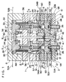
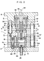
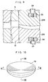
- An injection molding assembly used for the injection molding method is shown in Fig. 1 to Fig. 3.
- Fig. 2 and Fig. 3 are sectional views taken along the II-II line and the III-III line in Fig.1.
- the injection molding assembly can be formed of optional material such as glass and ceramic besides metal.
- Material for spectacle lenses as molded products is a thermoplastic resin such as PMMA (polymethyl methacrylate), and PC (polycarbonate).
- the injection molding assembly is composed of an upper mold 1 and a lower mold 2.
- the upper mold 1 is a movable mold which opens and closes vertically in relation to the lower mold 2 as s fixed mold, and a parting line PL extends horizontally.
- the upper mold 1 is composed of a mold body 3 on a lower side and a die fitting member 4 in an upper side.
- the mold body 3 is provided with insert guides 5, mold plates 6 and 7 and the like.
- the die fitting member 4 is provided with an upper member 8 and a lower member 9 and the like.
- the lower mold 2 is composed of insert guides 10, mold plates 11 and 12, a sprue bush 13 and the like.
- the mold body 3 of the upper mold 1 is mounted on the die fitting member 4 with a bolt 14.
- the mold body 3 is mounted being guided to the lower mold 2 by means of a guide rod 15 to be freely movable within a margin S.
- the margin S is opened between the mold body 3 and the die fitting member 4.
- the mold body 3 is always resiliently biased downward by means of a plate spring 16 attached on an outer periphery of the bolt 14.
- a clamping cylinder (not shown) is provided above the die fitting member 4 which is mounted on the clamping cylinder.
- the clamping cylinder By the clamping cylinder the die fitting member 4 and the mold body 3 vertically move and the upper mold 1 composed of the mold body 3 and the die fitting member 4 vertically moves to open and close in relation to the lower mold 2.
- This vertical movement is conducted while an end portion 15A of the guide rod 15 in the upper mold 1 is inserted into and pulled out from a guide pipe 17 in the lower mold 2.
- the upper mold 1 and the lower mold 2 are aligned in closing the mold by a positioning pin 18 in the upper mold 1 being inserted in a positioning sleeve 19 in the lower mold 2.
- a margin setting cylinder (not shown) is provided below the lower mold 2.
- An upper mold insert 20 is put into the insert guide 5 mounted on the mold body 3 in the upper mold 1 movably in vertical direction.
- a lower mold insert 21 is put into the insert guide 10 provided in the lower mold 2 so as to be movably in vertical direction.
- a cavity 22 for molding a spectacle lens is formed. As shown in Fig. 1, two of the cavities 22 are provided on right and left sides in the present embodiment. Therefore, the injection molding assembly is used for molding two spectacle lenses simultaneously.
- the upper mold insert 20 and the lower mold insert 21 form the cavity 22 with the insert guides 5 and 10, that is, the inserts 20 and 21 are cavity forming members.
- the upper mold insert 20 is a cavity forming member for shaping a concave surface of the lens
- the lower mold insert 21 is a cavity forming member for shaping a convex surface of the lens.
- Each of the upper mold inserts 20 is attached to a piston rod 24 of a hydraulic cylinder 23 disposed downward through a T-shaped clamping member 25, the hydraulic cylinder 23 being built in the die fitting member 4 in the upper mold 1 so as to be slidable vertically.
- Each of the lower mold inserts 21 is attached to a piston rod 27 of a hydraulic cylinder 26 disposed upward through a T-shaped clamping member 28, the hydraulic cylinder being fixed on the lower mold 2.
- a back insert 29, in which the piston rod 24 is inserted to be slidable vertically, is fixed on a lower surface of the hydraulic cylinder 23.
- T-shaped slots of the inserts 20 and 21, with which the T-shaped clamping members 25 and 28 are engaged extend to an outer region of the inserts 20 and 21 for opening so that the inserts 20 and 21 are, respectively, inserted in and released from the piston rods 24 and 27, on which the T-shaped clamping members 25 and 28 are mounted, by engagement and disengagement of the T-shaped clamping members 25 and 28 with/from the T-shaped slots.
- a pressure receiving member 30 mounted on an upper surface of the hydraulic cylinder 23 is accommodated inside a recessed portion 8A of the upper member 8 composing the die fitting member 4 in the upper mold 1.
- a pair of guide bars 31 slidably inserted in the lower member 9 of the die fitting member 4 are hung from the pressure receiving member 30.
- springs 32 attached on outer peripheries of the guide bars 31, the pressure receiving member 30, the hydraulic cylinder 23, and the back insert 29 are always resiliently biased upward oppositely to the lower mold 2 and the pressure receiving member 30 abuts on an upper surface of the recessed portion 8A formed downward in relation to the upper member 8 of the die fitting member 4.
- a through-hole 33 leading to the recessed portion 8A is formed in the upper member 8 of the mold attaching member 4.
- An eject pin 34 is inserted in the through-hole 33 to move vertically by an eject cylinder (not shown).
- the eject pin 34 abuts on the pressure receiving member 30, and with descent of the eject pin 34 by means of the eject cylinder, the pressure receiving member 30, the hydraulic cylinder 23, the back insert 29, and the upper mold insert 20 are pressurized to move downward in relation to the upper mold 1.
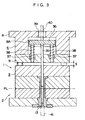
- an eject bar 35 is inserted to be movable vertically in central parts of the mold body 3 of the upper mold 1 and the lower member 9 of the die fitting member 4.
- a pair of guide bars 37 vertically slidably inserted in the lower member 9, are fixedly hung from an pressure receiving member 36 mounted on an upper end of the eject bar 35 as shown in Fig. 3.
- springs 38 attached on outer peripheries of the guide bars 37, a pressure receiving member 36 and the eject bar 35 are always resiliently biased upward.
- An eject pin 40 which is moved vertically with an eject cylinder (not shown), is inserted in a through-hole 39 formed in the upper member 8 of the die fitting member 4. With the eject pin 40, the pressure receiving member 36 and the eject bar 35 are pressurized to move downward.
- an injection nozzle 41 in an injection molding machine is connected to the sprue bush 13.
- a runner 43 is connected to an upper end of a sprue 42 in the sprue bush 13, the runner 43 extending to the cavities 22 provided on right and left side.
- Main lines 52 to 55 extend from a temperature controlling fluid feeder 51 controlled by a controller 50. End portions of the main lines 52 to 55 lead to branch lines 52A, 52B, 53A, 53B, 54A, 54B,55A, and 55B.
- the branch lines in pair for every main line 52 to 55 are disposed correspondingly to two cavities 22 provided on both sides shown in Fig. 1.
- the branch lines 52A and 52B are connected to ring slots 57 formed on upper surfaces of two right and left upper mold inserts 20 through passages 56
- the branch lines 53A and 53B are connected to ring slots 59 formed on lower surfaces of two right and left lower mold inserts 21 through passages 58
- the branch lines 54A and 54B are connected to peripheral slots 61 formed on side surfaces of two right and left upper mold insert guides 5 through passages 60
- branch lines 55A and 55B are connected to peripheral slots 63 formed on side surfaces of two right and left lower mold insert guides 10 through passages 62.
- the temperature controlling fluid feeder 51 shown in Fig. 4 circulates a heating fluid and a cooling fluid through the aforementioned main lines, branch lines, passages, ring slots and peripheral slots so as to raise and lower the temperature of the injection molding assembly, more specifically, temperature around the cavities 22 inside the injection molding assembly.
- the heating fluid is steam and the cooling fluid is air and water, for example.
- the temperature controlling fluid feeder 51 has a switching valve to switch over the heating fluid and the cooling fluid, a closing valve to supply and suspend the fluids and the like.
- the switching valves, the closing valves and the like are controlled by means of signal from the controller 50 which controls the heating and cooling time of the injection molding assembly by the heating fluid and the cooling fluid from the temperature controlling fluid feeder 51.
- a discharge line, for discharging the heating fluid and the cooling fluid supplied to the injection molding assembly is provided in the injection molding assembly, though not shown in the drawing.
- a molding process of a plastic lens for glasses using the injection molding assembly is conducted as follows.
- the upper mold 1 and the lower mold 2 are closed by the clamping cylinder.
- the margin S is opened between the mold body 3 of the upper mold 1 and the die fitting member 4 upon operation of the margin setting cylinder and a molten resin is ready to be filled in the cavity 22,
- the injection molding assembly is heated by supplying the heating fluid from the temperature controlling fluid feeder 51 to raise the temperature of the cavity 22 beyond flow halting temperature of the molten resin.
- the molten resin is injected from the injection nozzle 41 to be filled in the cavity 22 through the sprue 42 and the runner 43, and the nozzle is shut thereafter.
- the die fitting member 4 is lowered by the clamping cylinder and the molten resin in the cavity 22 is pressurized by the amount corresponding to the margin S by the upper mold insert 20.
- the cooling fluid is supplied to the injection molding assembly from the temperature controlling fluid feeder 51.
- the temperature of the molten resin in the cavity 22 is lowered to, for example, around 100 degrees centigrade below the glass transition point for molding spectacle lens by cooling and solidification of the molten resin.
- the upper mold 1 is opened from the lower mold 2 by the clamping cylinder. With the descent of the eject pins 34 and 40, a molded product is pushed out by the upper mold insert 20 and the eject bar 35. Subsequently, the molded product provided with two spectacle lenses ejected from the injection molding assembly as described above is cut to obtain the spectacle lenses molded in the cavities 22.
- the upper mold insert 20 and the lower mold insert 21 are exchangeable as stated above.
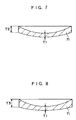
- a minus lens 71 having larger a thickness T2 of a peripheral portion than a thickness T1 of a central portion is molded as shown in Figs. 6 and 7.
- Fig. 8 is a sectional view taken in a direction perpendicular to Fig. 7.
- a thickness T3 of a peripheral portion is larger than the thickness T2 thus making the minus lens 71 as astigmatic spectacle lens by the difference between T2 and T3.
- molding process is conducted using an upper mold insert 20B and a lower mold insert 21B shown in Fig.
- a plus lens 72 having smaller thickness T5 of peripheral portion than a thickness T4 of a central portion can be molded as shown in Figs. 10 and 11.
- Fig. 12 is a sectional view in a right-angled direction perpendicular to Fig. 11.
- a thickness T6 of peripheral portion is larger than T5, thus making the plus lens 72 as astigmatic spectacle lens by the difference between T5 and T6.
- Upper mold inserts and lower mold inserts are respectively prepared correspondingly to every lens power (diopter) of minus lenses and plus lenses. Besides, another upper mold insert and a lower mold insert are provided for molding a semi-finished lens, having one surface already finished and the other surface to be later finished.
- FIG. 13 shows temperature curve of upper mold inserts and lower mold inserts in molding various kinds of lenses with a diameter of 76 millimeter from pressurization of the molten resin to ejection of the molded product.
- Fig. 13 (A) to (D) correspond to each lens shape and /or power.
- Fig. 13 (A) shows a case of molding a minus lens (weak minus lens) with a power of -2.00, T1 of 1.4mm and T2 of 4.8mm
- Fig. 13 (B) shows a case of molding a minus lens (strong minus lens) with a power of -4.00, T1 of 1.4mm and T2 of 7.9mm
- Fig. 13 (A) shows a case of molding a minus lens (weak minus lens) with a power of -2.00, T1 of 1.4mm and T2 of 4.8mm
- Fig. 13 (B) shows a case of molding a minus lens (strong minus lens) with a power of
- FIG. 13 (C) shows a case of molding a plus lens with a power of +2.00, T4 of 4.2mm and T5 of 1.0mm
- Fig. 13 (D) shows a case of molding a semi-finished lens with a base curve of convex surface of 3.00D, a thickness of a central portion of 5.4mm and a thickness of a peripheral portion of 5.8mm.
- These figures are for explaining basic lens molding patterns (basic lens molding patterns of a weak minus lens, a strong minus lens, a semi-finished lens and a plus lens) corresponding to each lens shape and/or power.
- a minus lens When a minus lens is molded as shown in Fig. 13 (A) and (B), the temperature of a lower mold insert (namely, a cavity forming member for shaping a convex surface of the lens) in ejecting a molded product from the injection molding assembly is lowered below the temperature of an upper mold insert (namely, a cavity forming member for shaping a concave surface of the lens).
- a lower mold insert namely, a cavity forming member for shaping a convex surface of the lens
- Table 1 shows the cooling time of the injection molding assembly from the start of supplying the aforementioned cooling liquid after pressurizing the molten resin to ejection of a molded product when a minus lens and a plus lens are molded.
- the cooling time is divided into groups according to lens power (diopter) (spherical power) and astigmatic power. Especially in the minus lens, the grouping is based on the value of the sum of the spherical power and the astigmatic power.
- the lens spehrical power is indicated in a vertical axis and the astigmatic power is indicated in a horizontal axis.
- a three-digit number in the Table 1 indicates a cooling time (second).
- the increase of lens power in a minus lens means that a thickness of the peripheral portion T2 becomes much larger than the thickness of the central portion T1.
- the increase of lens power in a plus lens means that a thickness of the central portion T4 becomes much larger than that of the peripheral portion T5.
- Table 1 the more a lens power increases, the longer a cooling time is made in both the minus lens and the plus lens.
- the cooling time is lengthened in proportion to the increase of the lens power, thereby gradually cooling the whole molten resin in the cavity 22 uniformly to a predetermined temperature (the temperature for ejecting the molded product). Consequently, a high-precision and high-quality plastic spectacle lens with little heat distortion, little shrinkage deformation and the like can be obtained.
- the cooling time of the injection molding assembly is lengthened in proportion to the increase of the lens power also in molding a semi-finished lens.
- a minus lens with the time from pressurization of molten resin to ejection of the molded product is made longer for minus lens having greater lens power in a minus lens with a smaller power even when the minus lenses have substantially the same surface area in the cavity, thereby lengthening a cooling time of the injection molding assembly.
- the temperature of the lower mold insert is lowered below the temperature of the upper mold insert and a cooling time of the injection molding assembly is lengthened as shown in Fig. 13 (A) and (B), which prevents the lens from bending at the central portion so as to enable high insert transfer precision and also prevents heat distortion, thus making a high-quality lens.
- peripheral portions T2 and T3 of a minus lens and the thickness of peripheral portions T5 and T6 of a plus lens respectively show the thickness of two points which are 90 degrees apart in a circumferential direction.
- the increase of difference between T2 and T3, and between T5 and T6 leads to the increase of astigmatic power.
- the volume of lens becomes larger and more molten resin is filled in the cavity 22 when an astigmatic power is made larger.
- the cavity forming member for shaping the lens convex surface is disposed on the lower mold and the cavity forming member for shaping the lens concave surface is disposed on the upper mold, but the reverse disposition is also available.
- the present invention can be also implemented by means of an injection molding assembly having horizontally-opposed cavity forming members.
- the heating fluid and the cooling fluid are used respectively for heating and cooling the injection molding assembly.
- the present invention is not limited to the above arrangement and preadjusted temperature controlling fluid may be used.
- a heating method by means of an electric heater and the like and a cooling method by means of forced air-cooling and the like can also be adopted.
- the cooling time required for cooling to the predetermined temperature is set in accordance with cooling methods.
- the temperature of the cavity forming member for shaping the lens convex surface is lowered below the temperature of the cavity forming member for shaping the lens concave surface, which prevents the molded lens from bending at a central portion.
- the shapes of the cavity forming members are highly-precisely transferred to the lens so that a high-precision and high-quality lens as desired can be obtained.
- the cooling time of the injection molding assembly after pressurization of the molten resin is lengthened for a lens with a large power requiring a larger amount of molten resin to be filled in the cavity, so that the entire molten resin can be uniformly cooled to the predetermined temperature. Consequently, a high-precision spectacle lens with little heat distortion and little shrinkage deformation and the like can be manufactured.
- a method of injection molding a plastic lens according to the present invention is applicable for molding a plastic lens for glasses, an optical plastic lens etc. made of a thermoplastic resin, and especially useful for molding a meniscus-shaped plastic lens for glasses which requires high-precision molding.
Landscapes
- Engineering & Computer Science (AREA)
- Manufacturing & Machinery (AREA)
- Mechanical Engineering (AREA)
- Health & Medical Sciences (AREA)
- Ophthalmology & Optometry (AREA)
- Moulds For Moulding Plastics Or The Like (AREA)
- Injection Moulding Of Plastics Or The Like (AREA)
Priority Applications (1)
| Application Number | Priority Date | Filing Date | Title |
|---|---|---|---|
| EP02012393A EP1273424B1 (fr) | 1997-03-18 | 1997-03-18 | Procédé de fabrication des lentilles en matière plastique |
Applications Claiming Priority (2)
| Application Number | Priority Date | Filing Date | Title |
|---|---|---|---|
| JP04269596A JP3264615B2 (ja) | 1996-02-29 | 1996-02-29 | プラスチックレンズの射出成形方法 |
| PCT/JP1997/000874 WO1998041379A1 (fr) | 1996-02-29 | 1997-03-18 | Procede de moulage par injection de lentilles plastiques |
Related Child Applications (1)
| Application Number | Title | Priority Date | Filing Date |
|---|---|---|---|
| EP02012393A Division EP1273424B1 (fr) | 1997-03-18 | 1997-03-18 | Procédé de fabrication des lentilles en matière plastique |
Publications (3)
| Publication Number | Publication Date |
|---|---|
| EP0955147A1 true EP0955147A1 (fr) | 1999-11-10 |
| EP0955147A4 EP0955147A4 (fr) | 2001-08-08 |
| EP0955147B1 EP0955147B1 (fr) | 2003-08-20 |
Family
ID=26382424
Family Applications (1)
| Application Number | Title | Priority Date | Filing Date |
|---|---|---|---|
| EP97907364A Expired - Lifetime EP0955147B1 (fr) | 1996-02-29 | 1997-03-18 | Procede de moulage par injection de lentilles plastiques |
Country Status (2)
| Country | Link |
|---|---|
| EP (1) | EP0955147B1 (fr) |
| WO (1) | WO1998041379A1 (fr) |
Cited By (9)
| Publication number | Priority date | Publication date | Assignee | Title |
|---|---|---|---|---|
| WO2000038901A1 (fr) * | 1998-12-31 | 2000-07-06 | Security Plastics, Inc. | Appareil a chemise d'eau pour systemes de moulage par injection |
| EP2848395A2 (fr) | 2013-09-11 | 2015-03-18 | Carl Zeiss Vision International GmbH | Produit fini ou semi-fini de verre de lunette, son procédé de fabrication et procédé de revêtement d'un produit fini ou semi-fini de verre de lunette |
| DE102014213393A1 (de) | 2014-07-10 | 2016-01-14 | Carl Zeiss Vision International Gmbh | Satz von Brillenglashalbfabrikaten und Verfahren zu dessen Auslegung, Verfahren und Vorrichtung zur Herstellung von Brillengläsern sowie Verwendung eines Satzes von Halbfabrikaten |
| EP3115188A1 (fr) | 2015-07-09 | 2017-01-11 | Carl Zeiss Vision International GmbH | Ébauche de verre de lunettes avec une géométrie adaptée à un processus de revêtement |
| EP3246746A1 (fr) | 2016-05-17 | 2017-11-22 | Carl Zeiss Vision International GmbH | Verre de lunette et procede de calcul et de fabrication d'un verre de lunette |
| EP3273292A1 (fr) | 2016-07-19 | 2018-01-24 | Carl Zeiss Vision International GmbH | Verre de lunette et son procede de fabrication |
| EP3311993A1 (fr) | 2016-10-20 | 2018-04-25 | Carl Zeiss Vision International GmbH | Verre de lunette et son procédé de fabrication |
| EP3543003A1 (fr) | 2018-03-23 | 2019-09-25 | Carl Zeiss Vision International GmbH | Palet de verre de lunettes ainsi que procédé et dispositif de fabrication d'un verre de lunettes à partir d'un palet de verre de lunettes |
| CN111712365A (zh) * | 2018-03-01 | 2020-09-25 | 依视路国际公司 | 具有在嵌件后冷却技术的模具及相关方法 |
Families Citing this family (2)
| Publication number | Priority date | Publication date | Assignee | Title |
|---|---|---|---|---|
| CN100522552C (zh) * | 2001-10-25 | 2009-08-05 | Ecim科技公司 | 用于成型薄壁产品的方法和设备以及由此制造的产品 |
| CN104859105B (zh) * | 2015-04-03 | 2017-06-20 | 华南理工大学 | 冷热双工位旋转式快速热循环注塑模具及成型方法 |
Citations (5)
| Publication number | Priority date | Publication date | Assignee | Title |
|---|---|---|---|---|
| GB1448511A (en) * | 1973-03-20 | 1976-09-08 | Montedison Spa | Injection moulding of plastic articles |
| EP0279972A2 (fr) * | 1987-02-24 | 1988-08-31 | Neolens, Inc | Equipement de moulage par injection et procédé |
| EP0339642A2 (fr) * | 1988-04-28 | 1989-11-02 | Aida Engineering Ltd. | Assemblage de moule, et procédés pour monter et enlever un insert et pour l'éjecter |
| JPH02164516A (ja) * | 1988-12-19 | 1990-06-25 | Hitachi Ltd | プラスチック凹レンズの成形方法及び成形金型 |
| EP0765734A2 (fr) * | 1995-09-29 | 1997-04-02 | JOHNSON & JOHNSON VISION PRODUCTS, INC. | Dispositif de moulure pour la réalisation d'un temps réduit du cycle de moulage |
Family Cites Families (9)
| Publication number | Priority date | Publication date | Assignee | Title |
|---|---|---|---|---|
| JPS59232835A (ja) * | 1983-06-15 | 1984-12-27 | Hitachi Ltd | 射出圧縮成形金型及びその成形方法 |
| JPS60212317A (ja) * | 1984-04-09 | 1985-10-24 | Canon Inc | 射出圧縮成形法 |
| JPS6119327A (ja) * | 1984-07-07 | 1986-01-28 | Hitachi Ltd | 射出圧縮成形方法および装置 |
| JPS61182918A (ja) * | 1985-02-12 | 1986-08-15 | Hitachi Ltd | 射出圧縮成形金型 |
| JPS6223723A (ja) * | 1985-07-24 | 1987-01-31 | Canon Inc | 射出圧縮成形方法 |
| JPS6260622A (ja) * | 1985-09-11 | 1987-03-17 | Hitachi Ltd | 射出圧縮成形金型 |
| JPS6260623A (ja) * | 1985-09-11 | 1987-03-17 | Hitachi Ltd | 射出圧縮成形方法および装置 |
| JPH01146718A (ja) * | 1987-12-03 | 1989-06-08 | Akimichi Koide | 金型制御装置 |
| JPH01275111A (ja) * | 1988-04-28 | 1989-11-02 | Aida Eng Ltd | 射出成形金型およびそのインサートの着脱方法 |
-
1997
- 1997-03-18 WO PCT/JP1997/000874 patent/WO1998041379A1/fr active IP Right Grant
- 1997-03-18 EP EP97907364A patent/EP0955147B1/fr not_active Expired - Lifetime
Patent Citations (5)
| Publication number | Priority date | Publication date | Assignee | Title |
|---|---|---|---|---|
| GB1448511A (en) * | 1973-03-20 | 1976-09-08 | Montedison Spa | Injection moulding of plastic articles |
| EP0279972A2 (fr) * | 1987-02-24 | 1988-08-31 | Neolens, Inc | Equipement de moulage par injection et procédé |
| EP0339642A2 (fr) * | 1988-04-28 | 1989-11-02 | Aida Engineering Ltd. | Assemblage de moule, et procédés pour monter et enlever un insert et pour l'éjecter |
| JPH02164516A (ja) * | 1988-12-19 | 1990-06-25 | Hitachi Ltd | プラスチック凹レンズの成形方法及び成形金型 |
| EP0765734A2 (fr) * | 1995-09-29 | 1997-04-02 | JOHNSON & JOHNSON VISION PRODUCTS, INC. | Dispositif de moulure pour la réalisation d'un temps réduit du cycle de moulage |
Non-Patent Citations (2)
| Title |
|---|
| PATENT ABSTRACTS OF JAPAN vol. 014, no. 420 (M-1023), 11 September 1990 (1990-09-11) & JP 02 164516 A (HITACHI LTD), 25 June 1990 (1990-06-25) * |
| See also references of WO9841379A1 * |
Cited By (24)
| Publication number | Priority date | Publication date | Assignee | Title |
|---|---|---|---|---|
| WO2000038901A1 (fr) * | 1998-12-31 | 2000-07-06 | Security Plastics, Inc. | Appareil a chemise d'eau pour systemes de moulage par injection |
| EP2848395A2 (fr) | 2013-09-11 | 2015-03-18 | Carl Zeiss Vision International GmbH | Produit fini ou semi-fini de verre de lunette, son procédé de fabrication et procédé de revêtement d'un produit fini ou semi-fini de verre de lunette |
| US9310521B2 (en) | 2013-09-11 | 2016-04-12 | Carl Zeiss Vision International Gmbh | Spectacle lens semi-finished product or spectacle lens finished product and method of making the same |
| DE102014213393A1 (de) | 2014-07-10 | 2016-01-14 | Carl Zeiss Vision International Gmbh | Satz von Brillenglashalbfabrikaten und Verfahren zu dessen Auslegung, Verfahren und Vorrichtung zur Herstellung von Brillengläsern sowie Verwendung eines Satzes von Halbfabrikaten |
| DE102014213393B4 (de) * | 2014-07-10 | 2016-12-29 | Carl Zeiss Vision International Gmbh | Satz von Brillenglashalbfabrikaten, computerimplementiertes Verfahren zu dessen Auslegung, Computerprogramm, computerlesbares Speichermedium, Verfahren und Vorrichtung zur Herstellung von Brillengläsern sowie Verwendung eines Satzes von Brillenglashalbfab |
| US9733492B2 (en) | 2014-07-10 | 2017-08-15 | Carl Zeiss Vision International Gmbh | Set of spectacle lens semifinished products, apparatus for making spectacle lenses and method therefor |
| EP3115188A1 (fr) | 2015-07-09 | 2017-01-11 | Carl Zeiss Vision International GmbH | Ébauche de verre de lunettes avec une géométrie adaptée à un processus de revêtement |
| EP3246746A1 (fr) | 2016-05-17 | 2017-11-22 | Carl Zeiss Vision International GmbH | Verre de lunette et procede de calcul et de fabrication d'un verre de lunette |
| WO2017198703A1 (fr) | 2016-05-17 | 2017-11-23 | Carl Zeiss Vision International Gmbh | Verre de lunettes et procédé de calcul et de fabrication d'un verre de lunettes |
| US11126013B2 (en) | 2016-05-17 | 2021-09-21 | Carl Zeiss Vision International Gmbh | Spectacle lens and method for calculating and producing a spectacle lens |
| US10845619B2 (en) | 2016-07-19 | 2020-11-24 | Carl Zeiss Vision International Gmbh | Spectacle lens and method for producing a spectacle lens |
| EP3273292A1 (fr) | 2016-07-19 | 2018-01-24 | Carl Zeiss Vision International GmbH | Verre de lunette et son procede de fabrication |
| US11633928B2 (en) | 2016-07-19 | 2023-04-25 | Carl Zeiss Vision International Gmbh | Spectacle lens and method for producing a spectacle lens |
| EP3492964A1 (fr) | 2016-07-19 | 2019-06-05 | Carl Zeiss Vision International GmbH | Verre de lunette et son procédé de fabrication |
| EP3499297A1 (fr) | 2016-07-19 | 2019-06-19 | Carl Zeiss Vision International GmbH | Verre de lunette et son procédé de fabrication |
| US11175517B2 (en) | 2016-07-19 | 2021-11-16 | Carl Zeiss Vision International Gmbh | Spectacle lens and method for producing a spectacle lens |
| WO2018015442A1 (fr) | 2016-07-19 | 2018-01-25 | Carl Zeiss Vision International Gmbh | Verre de lunettes et son procédé de fabrication |
| EP3311993A1 (fr) | 2016-10-20 | 2018-04-25 | Carl Zeiss Vision International GmbH | Verre de lunette et son procédé de fabrication |
| US11543680B2 (en) | 2016-10-20 | 2023-01-03 | Carl Zeiss Vision International Gmbh | Spectacle lens and method for producing same |
| WO2018073295A1 (fr) | 2016-10-20 | 2018-04-26 | Carl Zeiss Vision International Gmbh | Verre de lunettes et procédé pour sa fabrication |
| CN111712365A (zh) * | 2018-03-01 | 2020-09-25 | 依视路国际公司 | 具有在嵌件后冷却技术的模具及相关方法 |
| WO2019180251A1 (fr) | 2018-03-23 | 2019-09-26 | Carl Zeiss Vision International Gmbh | Ébauche de verre de lunettes ainsi que procédé et dispositif pour la fabrication d'un verre de lunettes à partir d'une ébauche de verre de lunettes |
| US11086141B2 (en) | 2018-03-23 | 2021-08-10 | Carl Zeiss Vision International Gmbh | Spectacle lens blank, and method and device for producing a spectacle lens from a spectacle lens blank |
| EP3543003A1 (fr) | 2018-03-23 | 2019-09-25 | Carl Zeiss Vision International GmbH | Palet de verre de lunettes ainsi que procédé et dispositif de fabrication d'un verre de lunettes à partir d'un palet de verre de lunettes |
Also Published As
| Publication number | Publication date |
|---|---|
| EP0955147B1 (fr) | 2003-08-20 |
| WO1998041379A1 (fr) | 1998-09-24 |
| EP0955147A4 (fr) | 2001-08-08 |
Similar Documents
| Publication | Publication Date | Title |
|---|---|---|
| US6156242A (en) | Method of injection molding plastic lens | |
| US5415817A (en) | Process for molding plastic lenses | |
| EP0972488B1 (fr) | Lentille d'essai en plastique, article moule par injection et appareil de moulage correspondant | |
| KR940010712B1 (ko) | 열가소성 수지의 사출 성형방법 및 장치 | |
| JP3096066B2 (ja) | レンズの製造方法、レンズ成形用射出成形型およびレンズ成形品 | |
| US6767482B2 (en) | Injection compression molding method and injection compression molding machine | |
| EP0778119B1 (fr) | Procédé de moulage par injection-compression d'un verre de lunettes | |
| US20030099794A1 (en) | Molding method of a resin molded article by a mold apparatus, the mold apparatus, the resin molded article, and a molding machine having the mold apparatus | |
| USRE38617E1 (en) | Method of injection molding plastic lens | |
| EP0955147B1 (fr) | Procede de moulage par injection de lentilles plastiques | |
| EP1370408B1 (fr) | Procede de moulage par injection | |
| KR20020011376A (ko) | 얇은 열가소성 렌즈 제조를 위한 성형 방법 | |
| US6645417B1 (en) | Gateless molding | |
| KR20090122349A (ko) | 플라스틱 렌즈 성형 방법 | |
| EP1273424B1 (fr) | Procédé de fabrication des lentilles en matière plastique | |
| JP3320302B2 (ja) | レンズの射出圧縮成形方法 | |
| JPH0544893B2 (fr) | ||
| JP3737873B2 (ja) | レンズの射出圧縮成形方法 | |
| CN214645411U (zh) | 一种微流控离心式测试卡盘镜面模具 | |
| JP3872921B2 (ja) | 射出圧縮成形方法および射出圧縮成形装置 | |
| JP2002160274A (ja) | プラスチック製眼鏡レンズの射出成形方法 | |
| US20210069952A1 (en) | Method for producing an optical lens and optical lens produced by said method | |
| CN210415320U (zh) | 打印机外壳制备模具 | |
| JPH0919940A (ja) | インサート成形品の成形装置およびその成形方法 | |
| JP2002192587A (ja) | 光ディスク成形用金型装置 |
Legal Events
| Date | Code | Title | Description |
|---|---|---|---|
| PUAI | Public reference made under article 153(3) epc to a published international application that has entered the european phase |
Free format text: ORIGINAL CODE: 0009012 |
|
| 17P | Request for examination filed |
Effective date: 19990507 |
|
| AK | Designated contracting states |
Kind code of ref document: A1 Designated state(s): DE FR GB NL SE |
|
| A4 | Supplementary search report drawn up and despatched |
Effective date: 20010625 |
|
| AK | Designated contracting states |
Kind code of ref document: A4 Designated state(s): DE FR GB NL SE |
|
| 17Q | First examination report despatched |
Effective date: 20011109 |
|
| GRAH | Despatch of communication of intention to grant a patent |
Free format text: ORIGINAL CODE: EPIDOS IGRA |
|
| GRAH | Despatch of communication of intention to grant a patent |
Free format text: ORIGINAL CODE: EPIDOS IGRA |
|
| GRAA | (expected) grant |
Free format text: ORIGINAL CODE: 0009210 |
|
| AK | Designated contracting states |
Designated state(s): DE FR GB NL SE |
|
| REG | Reference to a national code |
Ref country code: GB Ref legal event code: FG4D |
|
| REF | Corresponds to: |
Ref document number: 69724285 Country of ref document: DE Date of ref document: 20030925 Kind code of ref document: P |
|
| PG25 | Lapsed in a contracting state [announced via postgrant information from national office to epo] |
Ref country code: SE Free format text: LAPSE BECAUSE OF FAILURE TO SUBMIT A TRANSLATION OF THE DESCRIPTION OR TO PAY THE FEE WITHIN THE PRESCRIBED TIME-LIMIT Effective date: 20031120 |
|
| ET | Fr: translation filed | ||
| PLBE | No opposition filed within time limit |
Free format text: ORIGINAL CODE: 0009261 |
|
| STAA | Information on the status of an ep patent application or granted ep patent |
Free format text: STATUS: NO OPPOSITION FILED WITHIN TIME LIMIT |
|
| 26N | No opposition filed |
Effective date: 20040524 |
|
| PGFP | Annual fee paid to national office [announced via postgrant information from national office to epo] |
Ref country code: NL Payment date: 20090315 Year of fee payment: 13 |
|
| REG | Reference to a national code |
Ref country code: NL Ref legal event code: V1 Effective date: 20101001 |
|
| PG25 | Lapsed in a contracting state [announced via postgrant information from national office to epo] |
Ref country code: NL Free format text: LAPSE BECAUSE OF NON-PAYMENT OF DUE FEES Effective date: 20101001 |
|
| REG | Reference to a national code |
Ref country code: FR Ref legal event code: PLFP Year of fee payment: 20 |
|
| PGFP | Annual fee paid to national office [announced via postgrant information from national office to epo] |
Ref country code: DE Payment date: 20160315 Year of fee payment: 20 |
|
| PGFP | Annual fee paid to national office [announced via postgrant information from national office to epo] |
Ref country code: GB Payment date: 20160316 Year of fee payment: 20 Ref country code: FR Payment date: 20160208 Year of fee payment: 20 |
|
| REG | Reference to a national code |
Ref country code: DE Ref legal event code: R071 Ref document number: 69724285 Country of ref document: DE |
|
| REG | Reference to a national code |
Ref country code: GB Ref legal event code: PE20 Expiry date: 20170317 |
|
| PG25 | Lapsed in a contracting state [announced via postgrant information from national office to epo] |
Ref country code: GB Free format text: LAPSE BECAUSE OF EXPIRATION OF PROTECTION Effective date: 20170317 |