EP0952069A2 - Transportanhänger - Google Patents
Transportanhänger Download PDFInfo
- Publication number
- EP0952069A2 EP0952069A2 EP99107702A EP99107702A EP0952069A2 EP 0952069 A2 EP0952069 A2 EP 0952069A2 EP 99107702 A EP99107702 A EP 99107702A EP 99107702 A EP99107702 A EP 99107702A EP 0952069 A2 EP0952069 A2 EP 0952069A2
- Authority
- EP
- European Patent Office
- Prior art keywords
- transport trailer
- vertical
- sheet metal
- trailer according
- longitudinal
- Prior art date
- Legal status (The legal status is an assumption and is not a legal conclusion. Google has not performed a legal analysis and makes no representation as to the accuracy of the status listed.)
- Granted
Links
- 239000002184 metal Substances 0.000 claims abstract description 12
- UQDJGEHQDNVPGU-UHFFFAOYSA-N serine phosphoethanolamine Chemical compound [NH3+]CCOP([O-])(=O)OCC([NH3+])C([O-])=O UQDJGEHQDNVPGU-UHFFFAOYSA-N 0.000 abstract 3
- 238000004519 manufacturing process Methods 0.000 description 3
- 229910000831 Steel Inorganic materials 0.000 description 2
- 239000010959 steel Substances 0.000 description 2
- 239000000853 adhesive Substances 0.000 description 1
- 230000001070 adhesive effect Effects 0.000 description 1
- 235000000396 iron Nutrition 0.000 description 1
- 230000000284 resting effect Effects 0.000 description 1
- XLYOFNOQVPJJNP-UHFFFAOYSA-N water Substances O XLYOFNOQVPJJNP-UHFFFAOYSA-N 0.000 description 1
Images
Classifications
-
- B—PERFORMING OPERATIONS; TRANSPORTING
- B62—LAND VEHICLES FOR TRAVELLING OTHERWISE THAN ON RAILS
- B62D—MOTOR VEHICLES; TRAILERS
- B62D25/00—Superstructure or monocoque structure sub-units; Parts or details thereof not otherwise provided for
- B62D25/20—Floors or bottom sub-units
- B62D25/2054—Load carrying floors for commercial vehicles
Definitions
- the invention relates to a transport trailer according to the preamble of Claim 1.
- a known transport trailer of this type has an outer frame which consists of four There are frame parts that are connected to each other via gusset plates.
- the in essential U-shaped frame parts have a vertical bend on the inside which is followed by a horizontal bend.
- the horizontal Bends in the frame parts support a wooden floor, the thickness of which is about corresponds to the aforementioned vertical deflection.
- At the ends are the frame parts mitred.
- Such a structure is expensive to manufacture. Does the Wish that the floor surface should be made of sheet metal, then it is necessary to Plank wooden floor with sheet metal. This not only makes the trailer more expensive, but also leads to the disadvantage that water, which between the Planking and the wooden floor can penetrate, leading to rotting of the wooden floor leads.
- a transport trailer of the type mentioned is the subject of US-A-3,612,569.
- This has two longitudinal beams, which are double T-shaped in cross section are.
- Cross members run at right angles to these side members.
- On the longitudinal and Cross members lie on a sheet metal base, the longitudinal edges of which are L-shaped are folded so that there is a U-shaped cross section at the edge.
- To the L-shaped angle irons are provided at the outer ends of the cross beams, one of which Leg with a cross member and the other leg with the bevel of the Are riveted to the sheet metal base. It is to be seen as a disadvantage that the edges of the Sheet metal base must be folded precisely, in particular the distance between the longitudinal bevels are exactly right, what the manufacture of the Transport trailer more expensive.
- the task is to create a transport trailer that is cheaper in the Manufacturing is.
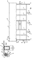
- the frame of the transport trailer has several cross members 1, one down have an open U-profile.
- the foremost and the rearmost cross members 2 consist of Square tubes.
- the cross member 1 connect two side members 3 made of square tubes that are in turn connected to the square tubes 2.
- the cross member 2 and the Side members 3 form the outer boundary of the frame.
- brackets 4 On the side members 3 are at right angles to the outside of the side members 3 protruding brackets 4 attached, which have a downwardly open U-shaped cross section have and have a vertically extending wall 5 at their free ends. This vertical walls 5 are each provided with a bore 6. The ends of the Cross member 2 and the ends of the brackets 4 run in the same alignment.
- consoles 4 each U-shaped in cross section Fixing bracket 7 attached, the vertical walls 5A also with a hole 6A are provided.
- the base 8 resting on the supports 1, 2, 3 consists of sheet steel.
- the one out Sheet steel existing floor 8 has an L-shaped edge 9 all around on that a downward vertical leg 10 and one for Bottom surface forms horizontal leg 11.
- the connection between the floor 8 and the frame is made using bolts 13. These are inserted into the holes 12 and 6 and 6A, the head of the Bolt 13 comes to rest on the leg 10 of the fold 9.
- a plastic sleeve 14 attached, which against the Bears on the inside of the leg 10 and runs through the bore 6 or 6A.
- the vertical leg 11 of the Bend 9 abuts the wall 5 or 5A when the nut 16 is dressed.
Landscapes
- Engineering & Computer Science (AREA)
- Chemical & Material Sciences (AREA)
- Combustion & Propulsion (AREA)
- Transportation (AREA)
- Mechanical Engineering (AREA)
- Body Structure For Vehicles (AREA)
- Tents Or Canopies (AREA)
- Package Frames And Binding Bands (AREA)
- Packaging Of Annular Or Rod-Shaped Articles, Wearing Apparel, Cassettes, Or The Like (AREA)
Abstract
Description
- Fig. 1
- eine Draufsicht auf den Rahmen des Transportanhängers mit teilweise abgeschnittenem Boden; und
- Fig. 2
- einen Schnitt längs der Linie II - II.
Claims (8)
- Transportanhänger mit einem Längs- und Querträger (1, 2, 3) aufweisenden rechteckigen Rahmen, auf dem ein Blechboden (8) angeordnet ist, der auf den Längs- und Querträgern (1, 2, 3) aufliegt und dessen längsverlaufende Ränder L-förmig abgekantet und mit dem Rahmen verbunden sind, dadurch gekennzeichnet, daß auch die querverlaufenden Ränder des Blechbodens (8) L-förmig abgekantet sind, an den Längsträgern (3) und an den äußeren Querträgern (2) rechtwinklig nach außen von den Trägern (2, 3) abstehende Konsolen (4) angeordnet sind, die jeweils eine äußere vertikale Wand (5, 5A) aufweisen und die vertikalen Schenkel (10) des L-förmigen Rands (9) des Blechbodens (8) mit den vertikalen Wänden (5, 5A) abständig verschraubt sind.
- Transportanhänger nach Anspruch 1, dadurch gekennzeichnet, daß die horizontalen Schenkel (11) des L-förmigen Rands (9) gegen die vertikalen Wände (5, 5A) anstoßen.
- Transportanhänger nach Anspruch 1 oder 2, dadurch gekennzeichnet, daß die vertikalen Schenkel (10) und die vertikalen Wände (5, 5A) über Schraubbolzen (13) miteinander verbunden sind.
- Transportanhänger nach Anspruch 3, dadurch gekennzeichnet, daß auf den Schraubbolzen (13) Kunststoffhülsen (14) angeordnet sind, welche in die Wandungsbohrungen (6, 6A) ragen und gegen die Wandungsränder der vertikalen Schenkel (10) anliegen.
- Transportanhänger nach einem der Ansprüche 1 bis 4, dadurch gekennzeichnet, daß der Blechboden (8) mindestens zum Teil an den Auflegestellen mit den Trägern (1, 2, 3) verklebt ist.
- Transportanhänger nach einem der Ansprüche 1 bis 5, dadurch gekennzeichnet, daß die Konsolen (4) der äußeren Querträger (2) aus U-förmigen Bügeln (7) bestehen, deren Mittelschenkel die vertikalen Wände (5A) bilden.
- Transportanhänger nach einem der Ansprüche 1 bis 6, dadurch gekennzeichnet, daß die Konsolen (4) der Längsträger (3) U-förmigen Querschnitt aufweisen.
- Transportanhänger nach einem der Ansprüche 1 bis 7, dadurch gekennzeichnet, daß an den Ecken des Blechbodens (8) an den vertikalen Schenkeln (10) Rungentaschen (17) befestigt sind.
Applications Claiming Priority (2)
| Application Number | Priority Date | Filing Date | Title |
|---|---|---|---|
| DE29807370U DE29807370U1 (de) | 1998-04-23 | 1998-04-23 | Transportanhänger |
| DE29807370U | 1998-04-23 |
Publications (3)
| Publication Number | Publication Date |
|---|---|
| EP0952069A2 true EP0952069A2 (de) | 1999-10-27 |
| EP0952069A3 EP0952069A3 (de) | 2000-03-22 |
| EP0952069B1 EP0952069B1 (de) | 2002-10-23 |
Family
ID=8056199
Family Applications (1)
| Application Number | Title | Priority Date | Filing Date |
|---|---|---|---|
| EP99107702A Expired - Lifetime EP0952069B1 (de) | 1998-04-23 | 1999-04-17 | Transportanhänger |
Country Status (3)
| Country | Link |
|---|---|
| EP (1) | EP0952069B1 (de) |
| DE (2) | DE29807370U1 (de) |
| DK (1) | DK0952069T3 (de) |
Cited By (2)
| Publication number | Priority date | Publication date | Assignee | Title |
|---|---|---|---|---|
| FR2859674A1 (fr) * | 2003-09-15 | 2005-03-18 | Rsa | Agencement d'une remorque tractee a plateau, et remorque a plateau ainsi agencee |
| DE202015105381U1 (de) | 2015-10-12 | 2017-01-13 | Ulrich Humbaur | Kippfahrzeug und Kippbrücke |
Families Citing this family (1)
| Publication number | Priority date | Publication date | Assignee | Title |
|---|---|---|---|---|
| DE202007011220U1 (de) | 2007-08-10 | 2008-12-24 | Leipold, Michael A. | Absperrvorrichtung für eine Tierbox |
Citations (1)
| Publication number | Priority date | Publication date | Assignee | Title |
|---|---|---|---|---|
| US3612569A (en) | 1969-01-29 | 1971-10-12 | Joseph A Marinelli | Trailer construction |
Family Cites Families (1)
| Publication number | Priority date | Publication date | Assignee | Title |
|---|---|---|---|---|
| JPS5631874A (en) * | 1979-08-24 | 1981-03-31 | Shin Meiwa Ind Co Ltd | Floor structure of motor truck |
-
1998
- 1998-04-23 DE DE29807370U patent/DE29807370U1/de not_active Expired - Lifetime
-
1999
- 1999-04-17 EP EP99107702A patent/EP0952069B1/de not_active Expired - Lifetime
- 1999-04-17 DE DE59903140T patent/DE59903140D1/de not_active Expired - Lifetime
- 1999-04-17 DK DK99107702T patent/DK0952069T3/da active
Patent Citations (1)
| Publication number | Priority date | Publication date | Assignee | Title |
|---|---|---|---|---|
| US3612569A (en) | 1969-01-29 | 1971-10-12 | Joseph A Marinelli | Trailer construction |
Cited By (5)
| Publication number | Priority date | Publication date | Assignee | Title |
|---|---|---|---|---|
| FR2859674A1 (fr) * | 2003-09-15 | 2005-03-18 | Rsa | Agencement d'une remorque tractee a plateau, et remorque a plateau ainsi agencee |
| DE202015105381U1 (de) | 2015-10-12 | 2017-01-13 | Ulrich Humbaur | Kippfahrzeug und Kippbrücke |
| DE102016119405A1 (de) | 2015-10-12 | 2017-04-13 | Ulrich Humbaur | Kippfahrzeug und Kippbrücke |
| DE102016119405B4 (de) | 2015-10-12 | 2022-10-13 | Humbaur Gmbh | Kippfahrzeug und Kippbrücke |
| DE102016016026B4 (de) * | 2015-10-12 | 2026-01-22 | Humbaur Gmbh | Kippfahrzeug und Kippbrücke |
Also Published As
| Publication number | Publication date |
|---|---|
| EP0952069A3 (de) | 2000-03-22 |
| DK0952069T3 (da) | 2002-11-25 |
| DE59903140D1 (de) | 2002-11-28 |
| EP0952069B1 (de) | 2002-10-23 |
| DE29807370U1 (de) | 1999-08-26 |
Similar Documents
| Publication | Publication Date | Title |
|---|---|---|
| DE2933429C2 (de) | In Modulbauweise gefertigter Eisenbahnwagen | |
| DE2629661A1 (de) | Verpackungssystem fuer den versand demontierbarer bauwerke | |
| EP0380953B1 (de) | Befestigungsvorrichtung für Wand- oder Deckenverkleidungsplatten | |
| DE9407796U1 (de) | Schutzzaun zur Absicherung von Gefahrzonen | |
| EP0952069B1 (de) | Transportanhänger | |
| DE9312522U1 (de) | Stützenfuß-System | |
| DE2226323A1 (de) | Langgestrecktes bauelement, insbesondere fuer das gerippe von haeusern, sowie verbindungsanordnung fuer solche bauelemente | |
| EP0079068B1 (de) | Anhänger für Kraftfahrzeuge | |
| DE8901471U1 (de) | Verbindungsstütze zur Erstellung von Container-Gehäusen bzw. Fertigbauraumkörpern | |
| DE19533157A1 (de) | Befestigungsanordnung einer Reling auf einem Fahrzeugdach | |
| DE2544598A1 (de) | Vorrichtung zur halterung von elementen, insbesondere bauelementen | |
| CH688486A5 (de) | Fassade. | |
| DE3231173C2 (de) | Verbundelement aus Hartschaumkern und Deckschichten | |
| DE202022107179U1 (de) | Untergestell und Tisch | |
| DE2543950C2 (de) | U-formiges Bauelement | |
| DE3909803A1 (de) | Industriefussboden aus miteinander verriegelten rechteckigen betonplatten | |
| DE4301081A1 (de) | Langgutträgerelement | |
| EP0197248B1 (de) | Unterzugschalung | |
| EP1001112B1 (de) | Gerüst für eine Schalung zur Herstellung einer Voute | |
| DE20112018U1 (de) | Doppelwinkelplatte | |
| DE1921986B2 (de) | Vorrichtung zum Verbinden einer Tragsäule mit Randbalken von vorgefertigten Gebäuden od.dgl | |
| DE102024104920A1 (de) | Balkon | |
| DE7027490U (de) | Transportfahrzeug. | |
| AT389907B (de) | Verbindung | |
| DE1429561C (de) | Vorrichtung zum Befestigen eines Fach bodens am Tragpfosten eines Regals |
Legal Events
| Date | Code | Title | Description |
|---|---|---|---|
| PUAI | Public reference made under article 153(3) epc to a published international application that has entered the european phase |
Free format text: ORIGINAL CODE: 0009012 |
|
| AK | Designated contracting states |
Kind code of ref document: A2 Designated state(s): BE DE DK FR IT NL |
|
| AX | Request for extension of the european patent |
Free format text: AL;LT;LV;MK;RO;SI |
|
| PUAL | Search report despatched |
Free format text: ORIGINAL CODE: 0009013 |
|
| AK | Designated contracting states |
Kind code of ref document: A3 Designated state(s): AT BE CH CY DE DK ES FI FR GB GR IE IT LI LU MC NL PT SE |
|
| AX | Request for extension of the european patent |
Free format text: AL;LT;LV;MK;RO;SI |
|
| 17P | Request for examination filed |
Effective date: 20000315 |
|
| AKX | Designation fees paid |
Free format text: BE DE DK FR IT NL |
|
| GRAG | Despatch of communication of intention to grant |
Free format text: ORIGINAL CODE: EPIDOS AGRA |
|
| GRAG | Despatch of communication of intention to grant |
Free format text: ORIGINAL CODE: EPIDOS AGRA |
|
| GRAH | Despatch of communication of intention to grant a patent |
Free format text: ORIGINAL CODE: EPIDOS IGRA |
|
| 17Q | First examination report despatched |
Effective date: 20020502 |
|
| GRAH | Despatch of communication of intention to grant a patent |
Free format text: ORIGINAL CODE: EPIDOS IGRA |
|
| GRAA | (expected) grant |
Free format text: ORIGINAL CODE: 0009210 |
|
| AK | Designated contracting states |
Kind code of ref document: B1 Designated state(s): BE DE DK FR IT NL |
|
| REG | Reference to a national code |
Ref country code: DK Ref legal event code: T3 |
|
| REF | Corresponds to: |
Ref document number: 59903140 Country of ref document: DE Date of ref document: 20021128 |
|
| ET | Fr: translation filed | ||
| PLBE | No opposition filed within time limit |
Free format text: ORIGINAL CODE: 0009261 |
|
| STAA | Information on the status of an ep patent application or granted ep patent |
Free format text: STATUS: NO OPPOSITION FILED WITHIN TIME LIMIT |
|
| 26N | No opposition filed |
Effective date: 20030724 |
|
| PGFP | Annual fee paid to national office [announced via postgrant information from national office to epo] |
Ref country code: FR Payment date: 20050414 Year of fee payment: 7 |
|
| PGFP | Annual fee paid to national office [announced via postgrant information from national office to epo] |
Ref country code: DK Payment date: 20050415 Year of fee payment: 7 |
|
| PGFP | Annual fee paid to national office [announced via postgrant information from national office to epo] |
Ref country code: BE Payment date: 20050502 Year of fee payment: 7 |
|
| PGFP | Annual fee paid to national office [announced via postgrant information from national office to epo] |
Ref country code: NL Payment date: 20050531 Year of fee payment: 7 |
|
| PG25 | Lapsed in a contracting state [announced via postgrant information from national office to epo] |
Ref country code: BE Free format text: LAPSE BECAUSE OF NON-PAYMENT OF DUE FEES Effective date: 20060430 |
|
| PGFP | Annual fee paid to national office [announced via postgrant information from national office to epo] |
Ref country code: IT Payment date: 20060430 Year of fee payment: 8 |
|
| PG25 | Lapsed in a contracting state [announced via postgrant information from national office to epo] |
Ref country code: DK Free format text: LAPSE BECAUSE OF NON-PAYMENT OF DUE FEES Effective date: 20060501 |
|
| PG25 | Lapsed in a contracting state [announced via postgrant information from national office to epo] |
Ref country code: NL Free format text: LAPSE BECAUSE OF NON-PAYMENT OF DUE FEES Effective date: 20061101 |
|
| REG | Reference to a national code |
Ref country code: DK Ref legal event code: EBP |
|
| NLV4 | Nl: lapsed or anulled due to non-payment of the annual fee |
Effective date: 20061101 |
|
| REG | Reference to a national code |
Ref country code: FR Ref legal event code: ST Effective date: 20061230 |
|
| BERE | Be: lapsed |
Owner name: *HUMBAUR G.M.B.H. Effective date: 20060430 |
|
| PG25 | Lapsed in a contracting state [announced via postgrant information from national office to epo] |
Ref country code: FR Free format text: LAPSE BECAUSE OF NON-PAYMENT OF DUE FEES Effective date: 20060502 |
|
| PG25 | Lapsed in a contracting state [announced via postgrant information from national office to epo] |
Ref country code: IT Free format text: LAPSE BECAUSE OF NON-PAYMENT OF DUE FEES Effective date: 20070417 |
|
| PGFP | Annual fee paid to national office [announced via postgrant information from national office to epo] |
Ref country code: DE Payment date: 20180512 Year of fee payment: 20 |
|
| REG | Reference to a national code |
Ref country code: DE Ref legal event code: R071 Ref document number: 59903140 Country of ref document: DE |