EP0951040B2 - Temperaturabhängiger Schalter - Google Patents
Temperaturabhängiger Schalter Download PDFInfo
- Publication number
- EP0951040B2 EP0951040B2 EP99100553.9A EP99100553A EP0951040B2 EP 0951040 B2 EP0951040 B2 EP 0951040B2 EP 99100553 A EP99100553 A EP 99100553A EP 0951040 B2 EP0951040 B2 EP 0951040B2
- Authority
- EP
- European Patent Office
- Prior art keywords
- switch
- terminal electrodes
- insulating support
- connection electrodes
- switching mechanism
- Prior art date
- Legal status (The legal status is an assumption and is not a legal conclusion. Google has not performed a legal analysis and makes no representation as to the accuracy of the status listed.)
- Expired - Lifetime
Links
- 230000007246 mechanism Effects 0.000 claims description 13
- 230000001419 dependent effect Effects 0.000 claims description 8
- 239000002184 metal Substances 0.000 claims description 8
- 230000000717 retained effect Effects 0.000 claims 1
- 230000013011 mating Effects 0.000 description 13
- 238000004519 manufacturing process Methods 0.000 description 6
- 230000008901 benefit Effects 0.000 description 5
- 238000010276 construction Methods 0.000 description 2
- 238000009413 insulation Methods 0.000 description 2
- 230000009471 action Effects 0.000 description 1
- 239000011324 bead Substances 0.000 description 1
- 150000001875 compounds Chemical class 0.000 description 1
- 239000004020 conductor Substances 0.000 description 1
- 230000009467 reduction Effects 0.000 description 1
- 230000004044 response Effects 0.000 description 1
- 238000007789 sealing Methods 0.000 description 1
- 239000000758 substrate Substances 0.000 description 1
Images

Classifications
-
- H—ELECTRICITY
- H01—ELECTRIC ELEMENTS
- H01H—ELECTRIC SWITCHES; RELAYS; SELECTORS; EMERGENCY PROTECTIVE DEVICES
- H01H1/00—Contacts
- H01H1/50—Means for increasing contact pressure, preventing vibration of contacts, holding contacts together after engagement, or biasing contacts to the open position
- H01H1/504—Means for increasing contact pressure, preventing vibration of contacts, holding contacts together after engagement, or biasing contacts to the open position by thermal means
Definitions
- the present invention relates to a temperature-dependent switch with two attached to an insulating support terminal electrodes, a switching mechanism which establishes an electrically conductive connection between the two terminal electrodes in dependence on its temperature, and a resistor part which is electrically connected in parallel to the switching mechanism with the two terminal electrodes ,
- Such a switch is from the DE-OS 21 13 388 known.
- the known switch is a thermostat for protecting an electrical device which is electrically connected in series with the device to be protected and in thermal contact with the device.
- the two terminal electrodes are flat metal parts, one of which carries a fixed mating contact and the other a bimetallic, at its free end a cooperating with the fixed counter-contact movable mating contact sits.
- the two metal parts are arranged one above the other and clamp between them a PTC resistor, which is in electrical contact with both terminal electrodes with the interposition of a spring.
- This construction of insulating support, metal parts with fixed and movable mating contact and PTC resistor is inserted into a housing, whereupon the housing opening is potted with a sealing compound.
- Another, self-holding temperature-dependent switch is from the DE 43 36 564 A1 known.
- This known switch comprises a arranged in an encapsulated housing bimetallic switching mechanism.
- the housing is arranged on a carrier plate, on which conductor tracks and resistors are provided. Outside the housing a PTC resistor is provided on the carrier, which is soldered parallel to the rear derailleur with external connections.
- the EP 0 272 696 A2 describes a temperature-dependent switch, in which on an insulating support, a resistor is arranged, which is connected via continuous through the insulation support rivets with two connected on opposite sides of the insulation support terminal electrodes in electrical connection. On the one rivet, a bimetallic switching element is fixed, which comes into contact with the other rivet depending on its temperature, so that an electrically conductive connection between the two terminal electrodes is produced. Due to the chosen construction, the resistance part is electrically parallel to the rear derailleur.
- the above-mentioned temperature-dependent switch in such a way that it is inexpensive and easy to assemble, preferably an exchange of the resistance member should be possible.
- the inventors of the present application have recognized that a surprisingly simple switch is provided when the resistive member is not disposed inside the switch or on a separate carrier adjacent to the switch, but is held immediately outside the insulating carrier.
- the switch can then be completely assembled before then the resistance part is subsequently placed from the outside. If the resistance part is omitted, the switch lacks the self-holding function, which is sufficient in many applications, however.
- the new switch thus has the advantage that the basic switch can be prefabricated and then provided with a resistor depending on your choice. Since in this way the basic switch can be made in a single production run in a much larger number, namely because the specialization of the switch is only subsequently determined, the overall result is a reduction in production costs, since the lot size in the manufacture of the basic switch be significantly greater can than the generic switch.
- the two terminal electrodes comprise flat metal parts, which are arranged side by side in a plane, and when the resistance part rests on the metal parts.
- the electrical connection between the resistor part and the terminal electrodes is effected by the geometrical arrangement of the resistor part on the terminal electrodes, where they are held by the insulating part.
- the insulating support is provided with projections which pinch the resistance member between them and press on the terminal electrodes.
- the one terminal electrode carries a fixed mating contact and the other carries a bimetal part, at the free end of which a movable mating contact cooperating with the fixed mating contact is seated.
- the resistance part is a PTC block.
- the outer surfaces may be formed in a known manner as connections.
- a temperature-dependent switch which comprises an insulating support 11, to which two in Fig. 1 dashed lines shown connecting electrodes 12, 13 are attached.
- the connection electrode 13 is L-shaped and the connection electrode 12 is Z-shaped, so that they face each other in the longitudinal axis 14 of the switch 10 with their contact ends 12a, 13a.
- terminal electrodes 12, 13 comprise flat metal parts, which are arranged side by side in a direction indicated at 15 level. Under the terminal electrodes 12, 13 are soldered leads 16, 17, which serve the external connection of the switch 10.
- a resistance part 18 On the terminal electrodes 12, 13 is a resistance part 18, which is a PTC block 19 in the embodiment shown.
- the insulating support 11 is at its sides with in Fig. 1 provided to the left, resilient projections 21, 22 which extend transversely to the plane 15 and extending from the plane of the Fig. 2 extend out.
- the projections 21, 22 clamp the PTC block 19 between them and engage over each with a bead 23 and 24, whereby the PTC block 19 is pressed onto the terminal electrodes 12, 13.
- the PTC block 19 may be in Fig. 1 be inserted laterally from the left between the terminal electrodes 12, 13 and the projections 21, 22 so that it sits outside of the insulating support 11, is held by this and at the same time in parallel between the two terminal electrodes 12, 13 is connected.
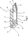
- a cavity 26 is provided in the insulating support 11, in which a temperature-dependent switching mechanism 27 is arranged.
- this cavity protrudes from the left, the terminal electrode 12 with its contact end 12a and from the right, the contact end 13a of the terminal electrode 13, wherein also in the region of the cavity 26, the two terminal electrodes 12, 13 lie on a plane.
- the terminal electrode 12 carries at its contact end 12a, a fixed mating contact 28 which cooperates with a movable mating contact 29 which is arranged at a free end of a bimetallic spring 31.
- the bimetallic spring 31 is connected to a bent portion 33 of the terminal electrode 13.
- the bimetallic spring 31 is in its low temperature position in which it presses the movable mating contact 29 against the fixed mating contact 28, so that an electrically conductive connection between the two terminal electrodes 12, 13 is produced.
- the switch 10 With its terminal electrodes 12, 13, the switch 10 is connected in series with an electrical device to be protected in an electrical circuit, wherein the operating current of the device via the terminal electrodes 12, 13 and the bimetal spring 31 is guided. Increases now the temperature of the switch 10 and thus the bimetallic spring 31 beyond the switching temperature, so the bimetal spring 31 lifts the movable mating contact 29 from the fixed mating contact 28, whereby the circuit is interrupted, so that the protected device off becomes.
- a residual current still flows through the PTC block 19, which is arranged electrically parallel to the switching mechanism 27.
- the residual current flowing through the PTC block 19 raises the temperature of the terminal electrodes 12, 13 so that heat is transferred to the inside of the switch 10 by heat conduction, thereby holding the bimetallic spring 31 above the switching temperature, so that the switch 10 turns does not automatically close again. Only after the power supply has been interrupted, the PTC block 19 and thus also the rest of the switch 10 cools down so far that the switching mechanism 27 can close again.
- the PTC block 19 can be designed differently from its resistance value, whereby different switching temperatures can be obtained. For this purpose, it is only necessary to push different PTC blocks 19 between the resilient projections 21, 22 and the terminal electrodes 12, 13.
Landscapes
- Thermally Actuated Switches (AREA)
- Thermistors And Varistors (AREA)
- Oscillators With Electromechanical Resonators (AREA)
- Control Of Combustion (AREA)
Description
- Die vorliegende Erfindung betrifft einen temperaturabhängigen Schalter mit zwei an einem Isolationsträger befestigten Anschlußelektroden, einem Schaltwerk, das in Abhängigkeit von seiner Temperatur eine elektrisch leitende Verbindung zwischen den beiden Anschlußelektroden herstellt, sowie einem Widerstandsteil, das elektrisch parallel zu dem Schaltwerk mit den beiden Anschlußelektroden verbunden ist.
- Ein derartiger Schalter ist aus der
DE-OS 21 13 388 - Der bekannte Schalter ist ein Thermostat zum Schutz eines elektrischen Gerätes, der elektrisch in Reihe mit dem zu schützenden Gerät geschaltet wird und in thermischem Kontakt mit dem Gerät ist.
- Die beiden Anschlußelektroden sind flächige Metallteile, von denen eines einen festen Gegenkontakt und das andere ein Bimetallteil trägt, an dessen freiem Ende ein mit dem festen Gegenkontakt zusammenwirkender beweglicher Gegenkontakt sitzt. Die beiden Metallteile sind übereinander angeordnet und klemmen zwischen sich einen PTC-Widerstand ein, der unter Zwischenschaltung einer Feder in elektrischem Kontakt mit beiden Anschlußelektroden steht.
- Dieser Aufbau aus Isolationsträger, Metallteilen mit festem und beweglichem Gegenkontakt sowie PTC-Widerstand wird in ein Gehäuse eingeschoben, woraufhin die Gehäuseöffnung mit einer Abdichtmasse vergossen wird.
- Wenn die Temperatur des zu schützenden Gerätes den Ansprechwert des Bimetallteiles übersteigt, hebt dieses den beweglichen von dem festen Gegenkontakt ab, wodurch die Stromzufuhr zu dem Gerät unterbrochen wird. Ein kleiner Reststrom fließt jetzt durch den parallel zu dem so gebildeten Schaltwerk angeordneten PTC-Widerstand, der dabei so viel Wärme entwickelt, daß er das Schaltwerk geöffnet hält; diese Funktion wird Selbsthaltung genannt.
- Bei dem bekannten Schalter ist von Nachteil, daß der PTC-Widerstand nur bei einem fertig montierten Schalter mechanisch hält, wobei die Montage dieses Schalters recht aufwendig ist. Der Austausch des PTC-Widerstandes ist nicht möglich.
- Ein weiterer, selbsthaltender temperaturabhängiger Schalter ist aus der
DE 43 36 564 A1 bekannt. Dieser bekannte Schalter umfaßt ein in einem gekapselten Gehäuse angeordnetes Bimetall-Schaltwerk. Das Gehäuse ist auf einer Trägerplatte angeordnet, auf der Leiterbahnen und Widerstände vorgesehen sind. Außerhalb des Gehäuses ist auf dem Träger ein PTC-Widerstand vorgesehen, der parallel zu dem Schaltwerk mit Außenanschlüssen verlötet ist. - Bei diesem Schalter ist von Nachteil, daß er zum einen relativ viele Bauteile benötigt und zum anderen große Abmessungen aufweist.
- Die
EP 0 272 696 A2 beschreibt einen temperaturabhängigen Schalter, bei dem auf einem Isolationsträger ein Widerstand angeordnet ist, der über durch den Isolationsträger durchgehende Nieten mit zwei auf gegenüberliegenden Seiten des Isolationsträgers verbundenen Anschlußelektroden in elektrischer Verbindung steht. An dem einen Niet ist ein Bimetall-Schaltelement befestigt, das in Abhängigkeit von seiner Temperatur in Anlage mit dem anderen Niet gelangt, so dass eine elektrisch leitende Verbindung zwischen den beiden Anschlußelektroden hergestellt wird. Durch die gewählte Konstruktion liegt das Widerstandsteil elektrisch parallel zu dem Schaltwerk. - Wie bei dem aus der
DE 21 13 388 A1 bekannten Schalter ist es auch hier nicht möglich, das Widerstandsteil auszutauschen oder nachträglich zu montieren. - Vor diesem Hintergrund ist es Aufgabe der vorliegenden Erfindung, den eingangs genannten temperaturabhängigen Schalter derart weiterzubilden, daß er preiswert und einfach zu montieren ist, wobei vorzugsweise ein Austausch des Widerstandsteiles möglich sein soll.
- Diese Aufgabe wird erfindungsgemäß bei dem eingangs genannten Schalter dadurch gelöst, daß das Schaltwerk in einem Hohlraum des Isolationsträgers angeordnet ist und das Widerstandsteil außen an dem Isolationsträger sitzt, von diesem gehalten wird und mit den Anschlußelektroden verlötet ist.
- Die der Erfindung zugrundeliegende Aufgabe wird auf diese Weise vollkommen gelöst.
- Die Erfinder der vorliegenden Anmeldung haben nämlich erkannt, daß ein überraschend einfacher Schalter geschaffen wird, wenn das Widerstandsteil nicht innen in dem Schalter oder auf einem gesonderten Träger neben dem Schalter angeordnet wird, sondern unmittelbar außen an dem Isolationsträger gehalten wird. Der Schalter kann dann zunächst vollständig konfektioniert werden, bevor dann das Widerstandsteil nachträglich von außen aufgesetzt wird. Wenn auf das Widerstandsteil verzichtet wird, fehlt dem Schalter die Selbsthaltefunktion, was in vielen Anwendungsfällen jedoch ausreichend ist.
- Soll der Schalter dagegen mit einer Selbsthaltefunktion versehen werden, so ist lediglich von außen das Widerstandsteil anzubringen, das mit den beiden Anschlußelektroden verlötet wird. Bei ein und demselben Grundschalter können jetzt wahlweise unterschiedliche Widerstandsteile eingesetzt werden, um unterschiedlichen Einsatzbedingungen bezüglich Betriebsstrom und Ansprechtemperatur gerecht zu werden. Damit ergibt sich ein großer Fertigungsvorteil, weil nämlich der Schalter als solches in großem Umfange vorgefertigt werden kann, so daß später nur noch die unterschiedlichen Widerstände zuzuführen sind. Diese Möglichkeit hat auch schon der aus der eingangs erwähnten
DE 43 36 564 A1 bekannte Schalter geboten, dort war die nachträgliche Montage des Widerstandsteiles jedoch sehr aufwendig. Die eingangs weiter erwähnteDE-OS 21 13 388 - Zusammenfassend bietet der neue Schalter also den Vorteil, daß der Grundschalter vorgefertigt und dann je nach Wahl mit einem Widerstand nachträglich versehen werden kann. Da auf diese Weise der Grundschalter in einem einzigen Fertigungsgang in sehr viel größerer Stückzahl hergestellt werden kann, weil nämlich die Spezialisierung des Schalters erst nachträglich festgelegt wird, ergibt sich insgesamt auch eine Senkung der Produktionskosten, da die Losgröße bei der Fertigung des Grundschalters deutlich größer sein kann als bei dem gattungsbildenden Schalter.
- In einer Weiterbildung ist es dann bevorzugt, wenn die beiden Anschlußelektroden flächige Metallteile umfassen, die nebeneinander in einer Ebene angeordnet sind, und wenn das Widerstandsteil auf den Metallteilen aufliegt.
- Auch diese Maßnahme ist montagetechnisch von Vorteil, die elektrische Verbindung zwischen dem Widerstandsteil und den Anschlußelektroden erfolgt durch die geometrische Anordnung des Widerstandsteiles auf den Anschlußelektroden, wo sie durch das Isolationsteil gehalten werden.
- Weiter ist es bevorzugt, wenn der Isolationsträger mit Vorsprüngen versehen ist, die das Widerstandsteil zwischen sich einklemmen und auf die Anschlußelektroden drücken.
- Auch diese Maßnahme ist montagetechnisch von Vorteil, das Widerstandsteil muß sozusagen nur von außen zwischen die Vorsprünge gedrückt werden, wo es dann durch deren Federwirkung gleichzeitig gehalten und auf die Anschlußelektroden gedrückt wird. Damit ist aber auch ein nachträglicher Austausch des Widerstandsteiles möglich, was unter bestimmten Einsatzbedingungen von Vorteil sein kann.
- Allgemein ist es noch bevorzugt, wenn die eine Anschlußelektrode einen festen Gegenkontakt und die andere ein Bimetallteil trägt, an dessen freiem Ende ein mit dem festen Gegenkontakt zusammenwirkender beweglicher Gegenkontakt sitzt.
- Bei dieser Maßnahme ist von Vorteil, daß ein technisch sehr einfaches Schaltwerk verwendet wird, bei dem der Betriebsstrom über das Bimetallteil selbst fließt, so daß auf ein weiteres Federteil verzichtet werden kann.
- Weiter ist es noch bevorzugt, wenn das Widerstandsteil ein PTC-Block ist.
- Hier ist montagetechnisch von Vorteil, daß ein leicht zu handhabender und leicht zu kontaktierender PTC-Block verwendet wird, dessen Außenflächen in bekannter Weise als Anschlüsse ausgebildet sein können.
- Weitere Vorteile ergeben sich aus der Beschreibung und der beigefügten Zeichnung. Es versteht sich, daß die vorstehend genannten und die nachstehend noch zu erläuternden Merkmale nicht nur in den jeweils angegebenen Kombinationen, sondern auch in anderen Kombinationen oder in Alleinstellung verwendbar sind, ohne den Rahmen der vorliegenden Erfindung zu verlassen.
- Ein Ausführungsbeispiel der Erfindung ist in der Zeichnung dargestellt und wird in der nachfolgenden Beschreibung näher erläutert. Es zeigen:
- Fig. 1
- eine Draufsicht auf einen schematisch gezeigten temperaturabhängigen Schalter mit gestrichelt angedeuteten Anschlußelektroden;
- Fig. 2
- eine Seitenansicht des Schalters längs der Linie II-II aus
Fig. 1 gesehen; und - Fig. 3
- eine Schnittdarstellung des Schalters längs der Linie III-III aus
Fig. 1 . - In
Fig. 1 ist mit 10 ein temperaturabhängiger Schalter bezeichnet, der einen Isolationsträger 11 umfaßt, an dem zwei inFig. 1 gestrichelt gezeigte Anschlußelektroden 12, 13 befestigt sind. Die Anschlußelektrode 13 ist L-förmig und die Anschlußelektrode 12 Z-förmig ausgebildet, so daß sie in der Längsachse 14 des Schalters 10 mit ihren Kontaktenden 12a, 13a aufeinander zu weisen. - Insbesondere aus
Fig. 2 ist zu erkennen, daß die Anschlußelektroden 12, 13 flächige Metallteile umfassen, die nebeneinander in einer bei 15 angedeuteten Ebene angeordnet sind. Unter die Anschlußelektroden 12, 13 sind Anschlußlitzen 16, 17 gelötet, die dem Außenanschluß des Schalters 10 dienen. - Auf den Anschlußelektroden 12, 13 liegt ein Widerstandsteil 18 auf, das in dem gezeigten Ausführungsbeispiel ein PTC-Block 19 ist.
- Der Isolationsträger 11 ist an seinen Seiten mit in
Fig. 1 nach links weisenden, federnden Vorsprüngen 21, 22 versehen, die quer zu der Ebene 15 verlaufen und sich aus der Zeichenebene derFig. 2 heraus erstrecken. Die Vorsprünge 21, 22 klemmen den PTC-Block 19 zwischen sich ein und übergreifen diesen mit jeweils einer Wulst 23 bzw. 24, wodurch der PTC-Block 19 auf die Anschlußelektroden 12, 13 gedrückt wird. Der PTC-Block 19 kann inFig. 1 seitlich von links zwischen die Anschlußelektroden 12, 13 sowie die Vorsprünge 21, 22 eingeschoben werden, so daß er außen an dem Isolationsträger 11 sitzt, von diesem gehalten wird und gleichzeitig parallel zwischen die beiden Anschlußelektroden 12, 13 geschaltet ist. - In der Schnittdarstellung der
Fig. 3 ist zu erkennen, daß in dem Isolationsträger 11 ein Hohlraum 26 vorgesehen ist, in dem ein temperaturabhängiges Schaltwerk 27 angeordnet ist. In diesen Hohlraum ragt von links die Anschlußelektrode 12 mit ihrem Kontaktende 12a sowie von rechts das Kontaktende 13a der Anschlußelektrode 13 hinein, wobei auch im Bereich des Hohlraumes 26 die beiden Anschlußelektroden 12, 13 auf einer Ebene liegen. - Die Anschlußelektrode 12 trägt an ihrem Kontaktende 12a einen festen Gegenkontakt 28, der mit einem beweglichen Gegenkontakt 29 zusammenarbeitet, der an einem freien Ende einer Bimetall-Feder 31 angeordnet ist. An ihrem anderen Ende 32 ist die Bimetall-Feder 31 mit einem abgekröpften Teil 33 der Anschlußelektrode 13 verbunden.
- In der in
Fig. 3 gezeigten Stellung befindet sich die Bimetall-Feder 31 in ihrer Tieftemperaturstellung, in der sie den beweglichen Gegenkontakt 29 gegen den festen Gegenkontakt 28 drückt, so daß eine elektrisch leitende Verbindung zwischen den beiden Anschlußelektroden 12, 13 hergestellt wird. Mit seinen Anschlußelektroden 12, 13 wird der Schalter 10 in Reihe mit einem zu schützenden elektrischen Gerät in einen elektrischen Stromkreis geschaltet, wobei der Betriebsstrom des Gerätes über die Anschlußelektroden 12, 13 sowie die Bimetall-Feder 31 geführt wird. Erhöht sich jetzt die Temperatur des Schalters 10 und damit der Bimetall-Feder 31 über die Schalttemperatur hinaus, so hebt die Bimetall-Feder 31 den beweglichen Gegenkontakt 29 von dem festen Gegenkontakt 28 ab, wodurch der Stromkreis unterbrochen wird, so daß das geschützte Gerät abgeschaltet wird. - Ein Reststrom fließt jedoch noch durch den PTC-Block 19, der elektrisch parallel zu dem Schaltwerk 27 angeordnet ist. Der durch den PTC-Block 19 fließende Reststrom erhöht die Temperatur der Anschlußelektroden 12, 13, so daß durch Wärmeleitung Wärme in das Innere des Schalters 10 gelangt, wodurch die Bimetall-Feder 31 auf oberhalb der Schalttemperatur gehalten wird, so daß der Schalter 10 sich nicht selbsttätig wieder schließt. Erst nachdem die Stromzufuhr unterbrochen wurde, kühlt sich der PTC-Block 19 und damit auch der Rest des Schalters 10 soweit ab, daß das Schaltwerk 27 wieder schließen kann.
- Der PTC-Block 19 kann dabei von seinem Widerstandswert her unterschiedlich ausgelegt sein, wodurch unterschiedliche Schalttemperaturen erhalten werden können. Dazu ist es lediglich erforderlich, unterschiedliche PTC-Blöcke 19 zwischen die federnden Vorsprünge 21, 22 sowie die Anschlußelektroden 12, 13 zu schieben.
Claims (5)
- Temperaturabhängiger Schalter mit zwei an einem Isolationsträger (11) befestigten Anschlußelektroden (12, 13), einem Schaltwerk (27), das in Abhängigkeit von seiner Temperatur eine elektrisch leitende Verbindung zwischen den beiden Anschlußelektroden (12, 13) herstellt, sowie einem Widerstandsteil (18), das elektrisch parallel zu dem Schaltwerk (27) mit den beiden Anschlußelektroden (12, 13) verbunden ist, dadurch gekennzeichnet, daß das Schaltwerk (27) in einem Hohlraum (26) des Isolationsträgers (11) angeordnet ist und das Widerstandsteil (18) außen an dem Isolationsträger (11) sitzt, von diesem gehalten wird und mit den Anschlußelektroden (12, 13) verlötet ist.
- Schalter nach Anspruch 1, dadurch gekennzeichnet, daß die beiden Anschlußelektroden (12, 13) flächige Metallteile umfassen, die nebeneinander in einer Ebene (15) angeordnet sind, und daß das Widerstandsteil (18) auf den Metallteilen aufliegt.
- Schalter nach Anspruch 1 oder 2, dadurch gekennzeichnet, daß der Isolationsträger (11) mit Vorsprüngen (21, 22) versehen ist, die das Widerstandsteil (18) zwischen sich einklemmen und auf die Anschlußelektroden (12, 13) drücken.
- Schalter nach einem der Ansprüche 1 bis 3, dadurch gekennzeichnet, daß die eine Anschlußelektrode (12) einen festen Gegenkontakt (28) und die andere Anschlußelektrode (13) ein Bimetallteil (31) trägt, an dessen freiem Ende ein mit dem festen Gegenkontakt (28) zusammenwirkender beweglicher Gegenkontakt (29) sitzt.
- Schalter nach einem der Ansprüche 1 bis 4, dadurch gekennzeichnet, daß das Widerstandsteil (18) ein PTC-Block (19) ist.
Applications Claiming Priority (2)
| Application Number | Priority Date | Filing Date | Title |
|---|---|---|---|
| DE19816807A DE19816807C2 (de) | 1998-04-16 | 1998-04-16 | Temperaturabhängiger Schalter |
| DE19816807 | 1998-04-16 |
Publications (4)
| Publication Number | Publication Date |
|---|---|
| EP0951040A2 EP0951040A2 (de) | 1999-10-20 |
| EP0951040A3 EP0951040A3 (de) | 2000-07-26 |
| EP0951040B1 EP0951040B1 (de) | 2008-07-30 |
| EP0951040B2 true EP0951040B2 (de) | 2017-03-15 |
Family
ID=7864678
Family Applications (1)
| Application Number | Title | Priority Date | Filing Date |
|---|---|---|---|
| EP99100553.9A Expired - Lifetime EP0951040B2 (de) | 1998-04-16 | 1999-01-13 | Temperaturabhängiger Schalter |
Country Status (6)
| Country | Link |
|---|---|
| US (1) | US6133817A (de) |
| EP (1) | EP0951040B2 (de) |
| AT (1) | ATE403229T1 (de) |
| AU (1) | AU745179B2 (de) |
| DE (2) | DE19816807C2 (de) |
| ES (1) | ES2311299T3 (de) |
Cited By (1)
| Publication number | Priority date | Publication date | Assignee | Title |
|---|---|---|---|---|
| EP3796359A1 (de) | 2019-09-20 | 2021-03-24 | Marcel P. Hofsaess | Temperaturabhängiger schalter |
Families Citing this family (16)
| Publication number | Priority date | Publication date | Assignee | Title |
|---|---|---|---|---|
| DE19847209C2 (de) * | 1998-10-13 | 2002-04-25 | Marcel Hofsaes | Schalter mit einem Isolierstoffträger |
| DE19909059C2 (de) * | 1999-03-02 | 2003-10-16 | Marcel Hofsaes | Schalter mit Verschweißsicherung |
| US6483418B1 (en) * | 2000-08-18 | 2002-11-19 | Texas Instruments Incorporated | Creep acting miniature thermostatic electrical switch and thermostatic member used therewith |
| JP4471479B2 (ja) * | 2000-10-13 | 2010-06-02 | ウチヤ・サーモスタット株式会社 | サーマルプロテクタ |
| US6756536B2 (en) | 2002-03-28 | 2004-06-29 | Bae Systems Information And Electronic Systems Integration Inc. | Thermoelectric microactuator |
| JP5000540B2 (ja) * | 2008-01-31 | 2012-08-15 | 新光電気工業株式会社 | スイッチング機能付配線基板 |
| DE102009061050B4 (de) | 2009-06-05 | 2019-09-05 | Marcel P. HOFSAESS | Bimetallteil und damit ausgestattete temperaturabhängige Schalter |
| DE102009025221A1 (de) | 2009-06-05 | 2010-12-16 | Hofsaess, Marcel P. | Bimetallteil und damit ausgestattete temperaturabhängige Schalter |
| DE102009030353B3 (de) * | 2009-06-22 | 2010-12-02 | Hofsaess, Marcel P. | Kappe für einen temperaturabhängigen Schalter sowie Verfahren zur Fertigung eines temperaturabhängigen Schalters |
| DE102009039948A1 (de) | 2009-08-27 | 2011-03-03 | Hofsaess, Marcel P. | Temperaturabhängiger Schalter |
| DE102013101393B4 (de) | 2013-02-13 | 2014-10-09 | Thermik Gerätebau GmbH | Temperaturabhängiger Schalter |
| DE102013022331B4 (de) | 2013-08-07 | 2020-10-29 | Thermik Gerätebau GmbH | Temperaturabhängiger Schalter |
| DE102013108508A1 (de) | 2013-08-07 | 2015-02-12 | Thermik Gerätebau GmbH | Temperaturabhängiger Schalter |
| DE102013108504C5 (de) | 2013-08-07 | 2018-11-15 | Thermik Gerätebau GmbH | Temperaturabhängiger Schalter |
| DE102014116888B4 (de) | 2014-11-18 | 2018-05-17 | Thermik Gerätebau GmbH | Temperaturabhängiger Schalter |
| DE102018130078B4 (de) | 2018-11-28 | 2020-10-15 | Marcel P. HOFSAESS | Temperaturabhängiger Schalter |
Citations (5)
| Publication number | Priority date | Publication date | Assignee | Title |
|---|---|---|---|---|
| DE2113388A1 (de) † | 1970-03-26 | 1971-10-14 | Texas Instruments Inc | Thermostat |
| DE2831198A1 (de) † | 1978-07-15 | 1980-01-24 | Limitor Ag | Bimetalltemperaturschalter |
| DE3128090A1 (de) † | 1979-07-21 | 1982-04-22 | Limitor AG, 8022 Zürich | "thermischer zeitschalter" |
| DE4142716A1 (de) † | 1991-12-21 | 1993-06-24 | Microtherm Gmbh | Thermoschalter |
| DE19509656C2 (de) † | 1995-03-17 | 1997-01-16 | Radbruch Jens Dipl Ing | Temperaturschutzschalter |
Family Cites Families (18)
| Publication number | Priority date | Publication date | Assignee | Title |
|---|---|---|---|---|
| GB134274A (en) * | 1918-10-24 | 1919-10-24 | Frank William Gunton | Improvements in Light Motor Cars, particularly those of the Cycle Car Type. |
| US2753421A (en) * | 1953-03-11 | 1956-07-03 | Stevens Mfg Co Inc | Thermostatic switches |
| US3265839A (en) * | 1963-08-05 | 1966-08-09 | Fasco Industries | Thermally-operable circuit breaker |
| US3308255A (en) * | 1964-06-08 | 1967-03-07 | Amf Electrica S P A | Ambient thermal protector with abutment contact reengagement means mounted on its case |
| US4399423A (en) * | 1982-03-29 | 1983-08-16 | Texas Instruments Incorporated | Miniature electric circuit protector |
| DE3320730A1 (de) * | 1983-01-15 | 1984-07-19 | Fritz Eichenauer GmbH & Co KG, 6744 Kandel | Temperaturwaechter |
| DE8300960U1 (de) * | 1983-01-15 | 1983-06-09 | Fritz Eichenauer GmbH & Co KG, 6744 Kandel | Temperaturwächter |
| EP0128978B1 (de) * | 1983-06-20 | 1987-09-02 | Texas Instruments Holland B.V. | Thermostat |
| US4620175A (en) * | 1985-10-11 | 1986-10-28 | North American Philips Corporation | Simple thermostat for dip mounting |
| DE3644514A1 (de) * | 1986-12-24 | 1988-07-07 | Inter Control Koehler Hermann | Bimetallschalter |
| JP2585148B2 (ja) * | 1991-04-05 | 1997-02-26 | ウチヤ・サーモスタット株式会社 | フィルム状発熱体内蔵型サーモスタット |
| GB9109316D0 (en) * | 1991-04-30 | 1991-06-19 | Otter Controls Ltd | Improvements relating to electric switches |
| DE4206157A1 (de) * | 1992-02-28 | 1993-09-16 | Hofsass P | Thermoschalter |
| DE9214940U1 (de) * | 1992-11-03 | 1992-12-17 | Thermik Geraetebau Gmbh, 7530 Pforzheim | Temperaturwächter |
| US5268664A (en) * | 1993-01-25 | 1993-12-07 | Portage Electric Products, Inc. | Low profile thermostat |
| DE4428226C1 (de) * | 1994-08-10 | 1995-10-12 | Thermik Geraetebau Gmbh | Temperaturwächter |
| DE19727197C2 (de) * | 1997-06-26 | 1999-10-21 | Marcel Hofsaess | Temperaturabhängiger Schalter mit Kontaktbrücke |
| DE19752581C2 (de) * | 1997-11-27 | 1999-12-23 | Marcel Hofsaes | Schalter mit einem temperaturabhängigen Schaltwerk |
-
1998
- 1998-04-16 DE DE19816807A patent/DE19816807C2/de not_active Expired - Fee Related
-
1999
- 1999-01-13 DE DE59914816T patent/DE59914816D1/de not_active Expired - Lifetime
- 1999-01-13 EP EP99100553.9A patent/EP0951040B2/de not_active Expired - Lifetime
- 1999-01-13 AT AT99100553T patent/ATE403229T1/de active
- 1999-01-13 ES ES99100553T patent/ES2311299T3/es not_active Expired - Lifetime
- 1999-04-12 US US09/289,821 patent/US6133817A/en not_active Expired - Lifetime
- 1999-04-15 AU AU23770/99A patent/AU745179B2/en not_active Ceased
Patent Citations (6)
| Publication number | Priority date | Publication date | Assignee | Title |
|---|---|---|---|---|
| DE2113388A1 (de) † | 1970-03-26 | 1971-10-14 | Texas Instruments Inc | Thermostat |
| GB1342274A (en) † | 1970-03-26 | 1974-01-03 | Texas Instruments Inc | Thermally operated switch |
| DE2831198A1 (de) † | 1978-07-15 | 1980-01-24 | Limitor Ag | Bimetalltemperaturschalter |
| DE3128090A1 (de) † | 1979-07-21 | 1982-04-22 | Limitor AG, 8022 Zürich | "thermischer zeitschalter" |
| DE4142716A1 (de) † | 1991-12-21 | 1993-06-24 | Microtherm Gmbh | Thermoschalter |
| DE19509656C2 (de) † | 1995-03-17 | 1997-01-16 | Radbruch Jens Dipl Ing | Temperaturschutzschalter |
Cited By (4)
| Publication number | Priority date | Publication date | Assignee | Title |
|---|---|---|---|---|
| EP3796359A1 (de) | 2019-09-20 | 2021-03-24 | Marcel P. Hofsaess | Temperaturabhängiger schalter |
| DE102019125453A1 (de) * | 2019-09-20 | 2021-03-25 | Marcel P. HOFSAESS | Temperaturabhängiger Schalter |
| EP4258315A2 (de) | 2019-09-20 | 2023-10-11 | Marcel P. Hofsaess | Temperaturabhängiger schalter |
| DE102019125453B4 (de) | 2019-09-20 | 2025-04-30 | Marcel P. HOFSAESS | Temperaturabhängiger Schalter |
Also Published As
| Publication number | Publication date |
|---|---|
| AU2377099A (en) | 1999-10-28 |
| ATE403229T1 (de) | 2008-08-15 |
| DE19816807A1 (de) | 1999-10-28 |
| EP0951040A3 (de) | 2000-07-26 |
| ES2311299T3 (es) | 2009-02-01 |
| DE59914816D1 (de) | 2008-09-11 |
| AU745179B2 (en) | 2002-03-14 |
| EP0951040B1 (de) | 2008-07-30 |
| DE19816807C2 (de) | 2000-06-08 |
| US6133817A (en) | 2000-10-17 |
| EP0951040A2 (de) | 1999-10-20 |
Similar Documents
| Publication | Publication Date | Title |
|---|---|---|
| EP0951040B2 (de) | Temperaturabhängiger Schalter | |
| EP0966014B1 (de) | Temperaturabhängiger Schalter mit Stromübertragungsglied | |
| EP0342441B1 (de) | Temperaturschalteinrichtung | |
| EP2846344B1 (de) | Temperaturabhängiger Schalter | |
| EP2511930B1 (de) | Temperaturschutzschalter | |
| EP0994498B1 (de) | Schalter mit einem Isolierstoffträger | |
| WO2008113489A1 (de) | Temperaturabhängiger schalter und dafür vorgesehenes schaltwerk | |
| DE19527253B4 (de) | Nach dem Baukastenprinzip aufgebauter Temperaturwächter | |
| DE69208705T2 (de) | Elektrothermisches Relais mit Schichtheizelement | |
| AT402983B (de) | Temperaturwächter | |
| DE19922633A1 (de) | Thermostat | |
| DE19705154C2 (de) | Temperaturabhängiger Schalter mit einem Bimetall-Schaltwerk | |
| EP0994497B1 (de) | Schalter mit einem Isolierstoffträger | |
| DE19636640C2 (de) | Schalter mit einem Sicherheitselement | |
| EP0951041B1 (de) | Temperaturabhängiger Schalter | |
| EP0114071A2 (de) | Temperaturwächter | |
| EP0453596A1 (de) | Temperaturschalter | |
| DE19546004C2 (de) | Schalter mit einem bei Übertemperatur schaltenden Schaltwerk | |
| EP0778597B1 (de) | Schalter mit einem bei Übertemperatur schaltenden Schaltwerk | |
| DE2540499C3 (de) | Temperaturregler für Elektrogeräte mit einer Ausdehnungsdose | |
| DE3711666A1 (de) | Temperaturschalter | |
| DE2511214C2 (de) | Temperaturregeleinrichtung für elektrische Geräte | |
| DE102008031389B3 (de) | Temperaturabhängiger Schalter | |
| DE69129468T2 (de) | Elektrischer rohrheizkörper mit einer temperaturkontrolleinrichtung | |
| DE4205699A1 (de) | Vorrichtung zum Schützen eines Geräts |
Legal Events
| Date | Code | Title | Description |
|---|---|---|---|
| PUAI | Public reference made under article 153(3) epc to a published international application that has entered the european phase |
Free format text: ORIGINAL CODE: 0009012 |
|
| AK | Designated contracting states |
Kind code of ref document: A2 Designated state(s): AT BE CH DE ES FR GB IT LI NL PT |
|
| AX | Request for extension of the european patent |
Free format text: AL;LT;LV;MK;RO;SI |
|
| PUAL | Search report despatched |
Free format text: ORIGINAL CODE: 0009013 |
|
| AK | Designated contracting states |
Kind code of ref document: A3 Designated state(s): AT BE CH CY DE DK ES FI FR GB GR IE IT LI LU MC NL PT SE |
|
| AX | Request for extension of the european patent |
Free format text: AL;LT;LV;MK;RO;SI |
|
| 17P | Request for examination filed |
Effective date: 20001122 |
|
| AKX | Designation fees paid |
Free format text: AT BE CH DE ES FR GB IT LI NL PT |
|
| RIN1 | Information on inventor provided before grant (corrected) |
Inventor name: GUETTINGER, EDWIN Inventor name: BECHER, MICHAEL Inventor name: HOFSAESS, MARCEL P. |
|
| RIN1 | Information on inventor provided before grant (corrected) |
Inventor name: GUETTINGER, EDWIN Inventor name: BECHER, MICHAEL Inventor name: HOFSAESS, MARCEL P. |
|
| GRAP | Despatch of communication of intention to grant a patent |
Free format text: ORIGINAL CODE: EPIDOSNIGR1 |
|
| RIN1 | Information on inventor provided before grant (corrected) |
Inventor name: GUETTINGER, EDWIN Inventor name: BECHER, MICHAEL Inventor name: HOFSAESS, MARCEL P. |
|
| GRAS | Grant fee paid |
Free format text: ORIGINAL CODE: EPIDOSNIGR3 |
|
| GRAA | (expected) grant |
Free format text: ORIGINAL CODE: 0009210 |
|
| AK | Designated contracting states |
Kind code of ref document: B1 Designated state(s): AT BE CH DE ES FR GB IT LI NL PT |
|
| REG | Reference to a national code |
Ref country code: GB Ref legal event code: FG4D Free format text: NOT ENGLISH |
|
| REG | Reference to a national code |
Ref country code: CH Ref legal event code: NV Representative=s name: TROESCH SCHEIDEGGER WERNER AG Ref country code: CH Ref legal event code: EP |
|
| REF | Corresponds to: |
Ref document number: 59914816 Country of ref document: DE Date of ref document: 20080911 Kind code of ref document: P |
|
| PG25 | Lapsed in a contracting state [announced via postgrant information from national office to epo] |
Ref country code: PT Free format text: LAPSE BECAUSE OF FAILURE TO SUBMIT A TRANSLATION OF THE DESCRIPTION OR TO PAY THE FEE WITHIN THE PRESCRIBED TIME-LIMIT Effective date: 20081230 |
|
| REG | Reference to a national code |
Ref country code: ES Ref legal event code: FG2A Ref document number: 2311299 Country of ref document: ES Kind code of ref document: T3 |
|
| PLBI | Opposition filed |
Free format text: ORIGINAL CODE: 0009260 |
|
| PLAX | Notice of opposition and request to file observation + time limit sent |
Free format text: ORIGINAL CODE: EPIDOSNOBS2 |
|
| 26 | Opposition filed |
Opponent name: TMC SENSORTECHNIK GMBH Effective date: 20090428 |
|
| NLR1 | Nl: opposition has been filed with the epo |
Opponent name: TMC SENSORTECHNIK GMBH |
|
| PLAF | Information modified related to communication of a notice of opposition and request to file observations + time limit |
Free format text: ORIGINAL CODE: EPIDOSCOBS2 |
|
| PLAF | Information modified related to communication of a notice of opposition and request to file observations + time limit |
Free format text: ORIGINAL CODE: EPIDOSCOBS2 |
|
| PLBB | Reply of patent proprietor to notice(s) of opposition received |
Free format text: ORIGINAL CODE: EPIDOSNOBS3 |
|
| PG25 | Lapsed in a contracting state [announced via postgrant information from national office to epo] |
Ref country code: BE Free format text: LAPSE BECAUSE OF NON-PAYMENT OF DUE FEES Effective date: 20090131 |
|
| APBM | Appeal reference recorded |
Free format text: ORIGINAL CODE: EPIDOSNREFNO |
|
| APBP | Date of receipt of notice of appeal recorded |
Free format text: ORIGINAL CODE: EPIDOSNNOA2O |
|
| APAH | Appeal reference modified |
Free format text: ORIGINAL CODE: EPIDOSCREFNO |
|
| APBM | Appeal reference recorded |
Free format text: ORIGINAL CODE: EPIDOSNREFNO |
|
| APBP | Date of receipt of notice of appeal recorded |
Free format text: ORIGINAL CODE: EPIDOSNNOA2O |
|
| APBQ | Date of receipt of statement of grounds of appeal recorded |
Free format text: ORIGINAL CODE: EPIDOSNNOA3O |
|
| RAP2 | Party data changed (patent owner data changed or rights of a patent transferred) |
Owner name: THERMIK GERAETEBAU GMBH |
|
| PGFP | Annual fee paid to national office [announced via postgrant information from national office to epo] |
Ref country code: GB Payment date: 20120120 Year of fee payment: 14 |
|
| REG | Reference to a national code |
Ref country code: DE Ref legal event code: R082 Ref document number: 59914816 Country of ref document: DE Representative=s name: WITTE, WELLER & PARTNER PATENTANWAELTE MBB, DE Effective date: 20120516 Ref country code: DE Ref legal event code: R081 Ref document number: 59914816 Country of ref document: DE Owner name: THERMIK GERAETEBAU GMBH, DE Free format text: FORMER OWNER: THERMIK GERAETEBAU GMBH, 75181 PFORZHEIM, DE Effective date: 20120516 |
|
| REG | Reference to a national code |
Ref country code: CH Ref legal event code: PFA Owner name: THERMIK GERAETEBAU GMBH Free format text: THERMIK GERAETEBAU GMBH#IM ALTGEFAELL 8#75181 PFORZHEIM (DE) -TRANSFER TO- THERMIK GERAETEBAU GMBH#SALZSTRASSE 11#99706 SONDERSHAUSEN (DE) |
|
| PGFP | Annual fee paid to national office [announced via postgrant information from national office to epo] |
Ref country code: NL Payment date: 20120125 Year of fee payment: 14 |
|
| REG | Reference to a national code |
Ref country code: FR Ref legal event code: CA Effective date: 20120702 |
|
| REG | Reference to a national code |
Ref country code: NL Ref legal event code: V1 Effective date: 20130801 |
|
| GBPC | Gb: european patent ceased through non-payment of renewal fee |
Effective date: 20130113 |
|
| PG25 | Lapsed in a contracting state [announced via postgrant information from national office to epo] |
Ref country code: NL Free format text: LAPSE BECAUSE OF NON-PAYMENT OF DUE FEES Effective date: 20130801 |
|
| PG25 | Lapsed in a contracting state [announced via postgrant information from national office to epo] |
Ref country code: GB Free format text: LAPSE BECAUSE OF NON-PAYMENT OF DUE FEES Effective date: 20130113 |
|
| PGFP | Annual fee paid to national office [announced via postgrant information from national office to epo] |
Ref country code: CH Payment date: 20140218 Year of fee payment: 16 |
|
| PGFP | Annual fee paid to national office [announced via postgrant information from national office to epo] |
Ref country code: ES Payment date: 20140226 Year of fee payment: 16 Ref country code: AT Payment date: 20140212 Year of fee payment: 16 Ref country code: IT Payment date: 20140131 Year of fee payment: 16 Ref country code: FR Payment date: 20140130 Year of fee payment: 16 |
|
| PGFP | Annual fee paid to national office [announced via postgrant information from national office to epo] |
Ref country code: DE Payment date: 20150220 Year of fee payment: 17 |
|
| REG | Reference to a national code |
Ref country code: CH Ref legal event code: PL |
|
| REG | Reference to a national code |
Ref country code: AT Ref legal event code: MM01 Ref document number: 403229 Country of ref document: AT Kind code of ref document: T Effective date: 20150113 |
|
| PG25 | Lapsed in a contracting state [announced via postgrant information from national office to epo] |
Ref country code: CH Free format text: LAPSE BECAUSE OF NON-PAYMENT OF DUE FEES Effective date: 20150131 Ref country code: LI Free format text: LAPSE BECAUSE OF NON-PAYMENT OF DUE FEES Effective date: 20150131 |
|
| REG | Reference to a national code |
Ref country code: FR Ref legal event code: ST Effective date: 20150930 |
|
| PG25 | Lapsed in a contracting state [announced via postgrant information from national office to epo] |
Ref country code: FR Free format text: LAPSE BECAUSE OF NON-PAYMENT OF DUE FEES Effective date: 20150202 Ref country code: AT Free format text: LAPSE BECAUSE OF NON-PAYMENT OF DUE FEES Effective date: 20150113 |
|
| PG25 | Lapsed in a contracting state [announced via postgrant information from national office to epo] |
Ref country code: IT Free format text: LAPSE BECAUSE OF NON-PAYMENT OF DUE FEES Effective date: 20150113 |
|
| REG | Reference to a national code |
Ref country code: ES Ref legal event code: FD2A Effective date: 20160226 |
|
| PG25 | Lapsed in a contracting state [announced via postgrant information from national office to epo] |
Ref country code: ES Free format text: LAPSE BECAUSE OF NON-PAYMENT OF DUE FEES Effective date: 20150114 |
|
| REG | Reference to a national code |
Ref country code: DE Ref legal event code: R119 Ref document number: 59914816 Country of ref document: DE |
|
| PG25 | Lapsed in a contracting state [announced via postgrant information from national office to epo] |
Ref country code: DE Free format text: LAPSE BECAUSE OF NON-PAYMENT OF DUE FEES Effective date: 20160802 |
|
| APAN | Information on closure of appeal procedure modified |
Free format text: ORIGINAL CODE: EPIDOSCNOA9O |
|
| APBU | Appeal procedure closed |
Free format text: ORIGINAL CODE: EPIDOSNNOA9O |
|
| PUAH | Patent maintained in amended form |
Free format text: ORIGINAL CODE: 0009272 |
|
| STAA | Information on the status of an ep patent application or granted ep patent |
Free format text: STATUS: PATENT MAINTAINED AS AMENDED |
|
| 27A | Patent maintained in amended form |
Effective date: 20170315 |
|
| AK | Designated contracting states |
Kind code of ref document: B2 Designated state(s): AT BE CH DE ES FR GB IT LI NL PT |
|
| REG | Reference to a national code |
Ref country code: DE Ref legal event code: R102 Ref document number: 59914816 Country of ref document: DE |