EP0949471B1 - Cryogenic air separation plant with two different operation modes - Google Patents
Cryogenic air separation plant with two different operation modes Download PDFInfo
- Publication number
- EP0949471B1 EP0949471B1 EP19990106715 EP99106715A EP0949471B1 EP 0949471 B1 EP0949471 B1 EP 0949471B1 EP 19990106715 EP19990106715 EP 19990106715 EP 99106715 A EP99106715 A EP 99106715A EP 0949471 B1 EP0949471 B1 EP 0949471B1
- Authority
- EP
- European Patent Office
- Prior art keywords
- air
- liquid
- pressure
- refrigeration
- rectification
- Prior art date
- Legal status (The legal status is an assumption and is not a legal conclusion. Google has not performed a legal analysis and makes no representation as to the accuracy of the status listed.)
- Expired - Lifetime
Links
Images
Classifications
-
- F—MECHANICAL ENGINEERING; LIGHTING; HEATING; WEAPONS; BLASTING
- F25—REFRIGERATION OR COOLING; COMBINED HEATING AND REFRIGERATION SYSTEMS; HEAT PUMP SYSTEMS; MANUFACTURE OR STORAGE OF ICE; LIQUEFACTION SOLIDIFICATION OF GASES
- F25J—LIQUEFACTION, SOLIDIFICATION OR SEPARATION OF GASES OR GASEOUS OR LIQUEFIED GASEOUS MIXTURES BY PRESSURE AND COLD TREATMENT OR BY BRINGING THEM INTO THE SUPERCRITICAL STATE
- F25J3/00—Processes or apparatus for separating the constituents of gaseous or liquefied gaseous mixtures involving the use of liquefaction or solidification
- F25J3/02—Processes or apparatus for separating the constituents of gaseous or liquefied gaseous mixtures involving the use of liquefaction or solidification by rectification, i.e. by continuous interchange of heat and material between a vapour stream and a liquid stream
- F25J3/04—Processes or apparatus for separating the constituents of gaseous or liquefied gaseous mixtures involving the use of liquefaction or solidification by rectification, i.e. by continuous interchange of heat and material between a vapour stream and a liquid stream for air
- F25J3/04763—Start-up or control of the process; Details of the apparatus used
- F25J3/04866—Construction and layout of air fractionation equipments, e.g. valves, machines
- F25J3/04951—Arrangements of multiple air fractionation units or multiple equipments fulfilling the same process step, e.g. multiple trains in a network
- F25J3/04957—Arrangements of multiple air fractionation units or multiple equipments fulfilling the same process step, e.g. multiple trains in a network and inter-connecting equipments upstream of the fractionation unit (s), i.e. at the "front-end"
-
- F—MECHANICAL ENGINEERING; LIGHTING; HEATING; WEAPONS; BLASTING
- F25—REFRIGERATION OR COOLING; COMBINED HEATING AND REFRIGERATION SYSTEMS; HEAT PUMP SYSTEMS; MANUFACTURE OR STORAGE OF ICE; LIQUEFACTION SOLIDIFICATION OF GASES
- F25J—LIQUEFACTION, SOLIDIFICATION OR SEPARATION OF GASES OR GASEOUS OR LIQUEFIED GASEOUS MIXTURES BY PRESSURE AND COLD TREATMENT OR BY BRINGING THEM INTO THE SUPERCRITICAL STATE
- F25J3/00—Processes or apparatus for separating the constituents of gaseous or liquefied gaseous mixtures involving the use of liquefaction or solidification
- F25J3/02—Processes or apparatus for separating the constituents of gaseous or liquefied gaseous mixtures involving the use of liquefaction or solidification by rectification, i.e. by continuous interchange of heat and material between a vapour stream and a liquid stream
- F25J3/04—Processes or apparatus for separating the constituents of gaseous or liquefied gaseous mixtures involving the use of liquefaction or solidification by rectification, i.e. by continuous interchange of heat and material between a vapour stream and a liquid stream for air
- F25J3/04006—Providing pressurised feed air or process streams within or from the air fractionation unit
- F25J3/04012—Providing pressurised feed air or process streams within or from the air fractionation unit by compression of warm gaseous streams; details of intake or interstage cooling
- F25J3/04018—Providing pressurised feed air or process streams within or from the air fractionation unit by compression of warm gaseous streams; details of intake or interstage cooling of main feed air
-
- F—MECHANICAL ENGINEERING; LIGHTING; HEATING; WEAPONS; BLASTING
- F25—REFRIGERATION OR COOLING; COMBINED HEATING AND REFRIGERATION SYSTEMS; HEAT PUMP SYSTEMS; MANUFACTURE OR STORAGE OF ICE; LIQUEFACTION SOLIDIFICATION OF GASES
- F25J—LIQUEFACTION, SOLIDIFICATION OR SEPARATION OF GASES OR GASEOUS OR LIQUEFIED GASEOUS MIXTURES BY PRESSURE AND COLD TREATMENT OR BY BRINGING THEM INTO THE SUPERCRITICAL STATE
- F25J3/00—Processes or apparatus for separating the constituents of gaseous or liquefied gaseous mixtures involving the use of liquefaction or solidification
- F25J3/02—Processes or apparatus for separating the constituents of gaseous or liquefied gaseous mixtures involving the use of liquefaction or solidification by rectification, i.e. by continuous interchange of heat and material between a vapour stream and a liquid stream
- F25J3/04—Processes or apparatus for separating the constituents of gaseous or liquefied gaseous mixtures involving the use of liquefaction or solidification by rectification, i.e. by continuous interchange of heat and material between a vapour stream and a liquid stream for air
- F25J3/04006—Providing pressurised feed air or process streams within or from the air fractionation unit
- F25J3/04012—Providing pressurised feed air or process streams within or from the air fractionation unit by compression of warm gaseous streams; details of intake or interstage cooling
- F25J3/04024—Providing pressurised feed air or process streams within or from the air fractionation unit by compression of warm gaseous streams; details of intake or interstage cooling of purified feed air, so-called boosted air
-
- F—MECHANICAL ENGINEERING; LIGHTING; HEATING; WEAPONS; BLASTING
- F25—REFRIGERATION OR COOLING; COMBINED HEATING AND REFRIGERATION SYSTEMS; HEAT PUMP SYSTEMS; MANUFACTURE OR STORAGE OF ICE; LIQUEFACTION SOLIDIFICATION OF GASES
- F25J—LIQUEFACTION, SOLIDIFICATION OR SEPARATION OF GASES OR GASEOUS OR LIQUEFIED GASEOUS MIXTURES BY PRESSURE AND COLD TREATMENT OR BY BRINGING THEM INTO THE SUPERCRITICAL STATE
- F25J3/00—Processes or apparatus for separating the constituents of gaseous or liquefied gaseous mixtures involving the use of liquefaction or solidification
- F25J3/02—Processes or apparatus for separating the constituents of gaseous or liquefied gaseous mixtures involving the use of liquefaction or solidification by rectification, i.e. by continuous interchange of heat and material between a vapour stream and a liquid stream
- F25J3/04—Processes or apparatus for separating the constituents of gaseous or liquefied gaseous mixtures involving the use of liquefaction or solidification by rectification, i.e. by continuous interchange of heat and material between a vapour stream and a liquid stream for air
- F25J3/04006—Providing pressurised feed air or process streams within or from the air fractionation unit
- F25J3/04078—Providing pressurised feed air or process streams within or from the air fractionation unit providing pressurized products by liquid compression and vaporisation with cold recovery, i.e. so-called internal compression
- F25J3/04084—Providing pressurised feed air or process streams within or from the air fractionation unit providing pressurized products by liquid compression and vaporisation with cold recovery, i.e. so-called internal compression of nitrogen
-
- F—MECHANICAL ENGINEERING; LIGHTING; HEATING; WEAPONS; BLASTING
- F25—REFRIGERATION OR COOLING; COMBINED HEATING AND REFRIGERATION SYSTEMS; HEAT PUMP SYSTEMS; MANUFACTURE OR STORAGE OF ICE; LIQUEFACTION SOLIDIFICATION OF GASES
- F25J—LIQUEFACTION, SOLIDIFICATION OR SEPARATION OF GASES OR GASEOUS OR LIQUEFIED GASEOUS MIXTURES BY PRESSURE AND COLD TREATMENT OR BY BRINGING THEM INTO THE SUPERCRITICAL STATE
- F25J3/00—Processes or apparatus for separating the constituents of gaseous or liquefied gaseous mixtures involving the use of liquefaction or solidification
- F25J3/02—Processes or apparatus for separating the constituents of gaseous or liquefied gaseous mixtures involving the use of liquefaction or solidification by rectification, i.e. by continuous interchange of heat and material between a vapour stream and a liquid stream
- F25J3/04—Processes or apparatus for separating the constituents of gaseous or liquefied gaseous mixtures involving the use of liquefaction or solidification by rectification, i.e. by continuous interchange of heat and material between a vapour stream and a liquid stream for air
- F25J3/04006—Providing pressurised feed air or process streams within or from the air fractionation unit
- F25J3/04078—Providing pressurised feed air or process streams within or from the air fractionation unit providing pressurized products by liquid compression and vaporisation with cold recovery, i.e. so-called internal compression
- F25J3/0409—Providing pressurised feed air or process streams within or from the air fractionation unit providing pressurized products by liquid compression and vaporisation with cold recovery, i.e. so-called internal compression of oxygen
-
- F—MECHANICAL ENGINEERING; LIGHTING; HEATING; WEAPONS; BLASTING
- F25—REFRIGERATION OR COOLING; COMBINED HEATING AND REFRIGERATION SYSTEMS; HEAT PUMP SYSTEMS; MANUFACTURE OR STORAGE OF ICE; LIQUEFACTION SOLIDIFICATION OF GASES
- F25J—LIQUEFACTION, SOLIDIFICATION OR SEPARATION OF GASES OR GASEOUS OR LIQUEFIED GASEOUS MIXTURES BY PRESSURE AND COLD TREATMENT OR BY BRINGING THEM INTO THE SUPERCRITICAL STATE
- F25J3/00—Processes or apparatus for separating the constituents of gaseous or liquefied gaseous mixtures involving the use of liquefaction or solidification
- F25J3/02—Processes or apparatus for separating the constituents of gaseous or liquefied gaseous mixtures involving the use of liquefaction or solidification by rectification, i.e. by continuous interchange of heat and material between a vapour stream and a liquid stream
- F25J3/04—Processes or apparatus for separating the constituents of gaseous or liquefied gaseous mixtures involving the use of liquefaction or solidification by rectification, i.e. by continuous interchange of heat and material between a vapour stream and a liquid stream for air
- F25J3/04006—Providing pressurised feed air or process streams within or from the air fractionation unit
- F25J3/04109—Arrangements of compressors and /or their drivers
- F25J3/04145—Mechanically coupling of different compressors of the air fractionation process to the same driver(s)
-
- F—MECHANICAL ENGINEERING; LIGHTING; HEATING; WEAPONS; BLASTING
- F25—REFRIGERATION OR COOLING; COMBINED HEATING AND REFRIGERATION SYSTEMS; HEAT PUMP SYSTEMS; MANUFACTURE OR STORAGE OF ICE; LIQUEFACTION SOLIDIFICATION OF GASES
- F25J—LIQUEFACTION, SOLIDIFICATION OR SEPARATION OF GASES OR GASEOUS OR LIQUEFIED GASEOUS MIXTURES BY PRESSURE AND COLD TREATMENT OR BY BRINGING THEM INTO THE SUPERCRITICAL STATE
- F25J3/00—Processes or apparatus for separating the constituents of gaseous or liquefied gaseous mixtures involving the use of liquefaction or solidification
- F25J3/02—Processes or apparatus for separating the constituents of gaseous or liquefied gaseous mixtures involving the use of liquefaction or solidification by rectification, i.e. by continuous interchange of heat and material between a vapour stream and a liquid stream
- F25J3/04—Processes or apparatus for separating the constituents of gaseous or liquefied gaseous mixtures involving the use of liquefaction or solidification by rectification, i.e. by continuous interchange of heat and material between a vapour stream and a liquid stream for air
- F25J3/04248—Generation of cold for compensating heat leaks or liquid production, e.g. by Joule-Thompson expansion
- F25J3/04284—Generation of cold for compensating heat leaks or liquid production, e.g. by Joule-Thompson expansion using internal refrigeration by open-loop gas work expansion, e.g. of intermediate or oxygen enriched (waste-)streams
- F25J3/0429—Generation of cold for compensating heat leaks or liquid production, e.g. by Joule-Thompson expansion using internal refrigeration by open-loop gas work expansion, e.g. of intermediate or oxygen enriched (waste-)streams of feed air, e.g. used as waste or product air or expanded into an auxiliary column
- F25J3/04296—Claude expansion, i.e. expanded into the main or high pressure column
-
- F—MECHANICAL ENGINEERING; LIGHTING; HEATING; WEAPONS; BLASTING
- F25—REFRIGERATION OR COOLING; COMBINED HEATING AND REFRIGERATION SYSTEMS; HEAT PUMP SYSTEMS; MANUFACTURE OR STORAGE OF ICE; LIQUEFACTION SOLIDIFICATION OF GASES
- F25J—LIQUEFACTION, SOLIDIFICATION OR SEPARATION OF GASES OR GASEOUS OR LIQUEFIED GASEOUS MIXTURES BY PRESSURE AND COLD TREATMENT OR BY BRINGING THEM INTO THE SUPERCRITICAL STATE
- F25J3/00—Processes or apparatus for separating the constituents of gaseous or liquefied gaseous mixtures involving the use of liquefaction or solidification
- F25J3/02—Processes or apparatus for separating the constituents of gaseous or liquefied gaseous mixtures involving the use of liquefaction or solidification by rectification, i.e. by continuous interchange of heat and material between a vapour stream and a liquid stream
- F25J3/04—Processes or apparatus for separating the constituents of gaseous or liquefied gaseous mixtures involving the use of liquefaction or solidification by rectification, i.e. by continuous interchange of heat and material between a vapour stream and a liquid stream for air
- F25J3/04248—Generation of cold for compensating heat leaks or liquid production, e.g. by Joule-Thompson expansion
- F25J3/04333—Generation of cold for compensating heat leaks or liquid production, e.g. by Joule-Thompson expansion using quasi-closed loop internal vapor compression refrigeration cycles, e.g. of intermediate or oxygen enriched (waste-)streams
- F25J3/04339—Generation of cold for compensating heat leaks or liquid production, e.g. by Joule-Thompson expansion using quasi-closed loop internal vapor compression refrigeration cycles, e.g. of intermediate or oxygen enriched (waste-)streams of air
- F25J3/04345—Generation of cold for compensating heat leaks or liquid production, e.g. by Joule-Thompson expansion using quasi-closed loop internal vapor compression refrigeration cycles, e.g. of intermediate or oxygen enriched (waste-)streams of air and comprising a gas work expansion loop
-
- F—MECHANICAL ENGINEERING; LIGHTING; HEATING; WEAPONS; BLASTING
- F25—REFRIGERATION OR COOLING; COMBINED HEATING AND REFRIGERATION SYSTEMS; HEAT PUMP SYSTEMS; MANUFACTURE OR STORAGE OF ICE; LIQUEFACTION SOLIDIFICATION OF GASES
- F25J—LIQUEFACTION, SOLIDIFICATION OR SEPARATION OF GASES OR GASEOUS OR LIQUEFIED GASEOUS MIXTURES BY PRESSURE AND COLD TREATMENT OR BY BRINGING THEM INTO THE SUPERCRITICAL STATE
- F25J3/00—Processes or apparatus for separating the constituents of gaseous or liquefied gaseous mixtures involving the use of liquefaction or solidification
- F25J3/02—Processes or apparatus for separating the constituents of gaseous or liquefied gaseous mixtures involving the use of liquefaction or solidification by rectification, i.e. by continuous interchange of heat and material between a vapour stream and a liquid stream
- F25J3/04—Processes or apparatus for separating the constituents of gaseous or liquefied gaseous mixtures involving the use of liquefaction or solidification by rectification, i.e. by continuous interchange of heat and material between a vapour stream and a liquid stream for air
- F25J3/04406—Processes or apparatus for separating the constituents of gaseous or liquefied gaseous mixtures involving the use of liquefaction or solidification by rectification, i.e. by continuous interchange of heat and material between a vapour stream and a liquid stream for air using a dual pressure main column system
- F25J3/04418—Processes or apparatus for separating the constituents of gaseous or liquefied gaseous mixtures involving the use of liquefaction or solidification by rectification, i.e. by continuous interchange of heat and material between a vapour stream and a liquid stream for air using a dual pressure main column system with thermally overlapping high and low pressure columns
-
- F—MECHANICAL ENGINEERING; LIGHTING; HEATING; WEAPONS; BLASTING
- F25—REFRIGERATION OR COOLING; COMBINED HEATING AND REFRIGERATION SYSTEMS; HEAT PUMP SYSTEMS; MANUFACTURE OR STORAGE OF ICE; LIQUEFACTION SOLIDIFICATION OF GASES
- F25J—LIQUEFACTION, SOLIDIFICATION OR SEPARATION OF GASES OR GASEOUS OR LIQUEFIED GASEOUS MIXTURES BY PRESSURE AND COLD TREATMENT OR BY BRINGING THEM INTO THE SUPERCRITICAL STATE
- F25J3/00—Processes or apparatus for separating the constituents of gaseous or liquefied gaseous mixtures involving the use of liquefaction or solidification
- F25J3/02—Processes or apparatus for separating the constituents of gaseous or liquefied gaseous mixtures involving the use of liquefaction or solidification by rectification, i.e. by continuous interchange of heat and material between a vapour stream and a liquid stream
- F25J3/04—Processes or apparatus for separating the constituents of gaseous or liquefied gaseous mixtures involving the use of liquefaction or solidification by rectification, i.e. by continuous interchange of heat and material between a vapour stream and a liquid stream for air
- F25J3/04436—Processes or apparatus for separating the constituents of gaseous or liquefied gaseous mixtures involving the use of liquefaction or solidification by rectification, i.e. by continuous interchange of heat and material between a vapour stream and a liquid stream for air using at least a triple pressure main column system
- F25J3/04448—Processes or apparatus for separating the constituents of gaseous or liquefied gaseous mixtures involving the use of liquefaction or solidification by rectification, i.e. by continuous interchange of heat and material between a vapour stream and a liquid stream for air using at least a triple pressure main column system in a double column flowsheet with an intermediate pressure column
-
- F—MECHANICAL ENGINEERING; LIGHTING; HEATING; WEAPONS; BLASTING
- F25—REFRIGERATION OR COOLING; COMBINED HEATING AND REFRIGERATION SYSTEMS; HEAT PUMP SYSTEMS; MANUFACTURE OR STORAGE OF ICE; LIQUEFACTION SOLIDIFICATION OF GASES
- F25J—LIQUEFACTION, SOLIDIFICATION OR SEPARATION OF GASES OR GASEOUS OR LIQUEFIED GASEOUS MIXTURES BY PRESSURE AND COLD TREATMENT OR BY BRINGING THEM INTO THE SUPERCRITICAL STATE
- F25J3/00—Processes or apparatus for separating the constituents of gaseous or liquefied gaseous mixtures involving the use of liquefaction or solidification
- F25J3/02—Processes or apparatus for separating the constituents of gaseous or liquefied gaseous mixtures involving the use of liquefaction or solidification by rectification, i.e. by continuous interchange of heat and material between a vapour stream and a liquid stream
- F25J3/04—Processes or apparatus for separating the constituents of gaseous or liquefied gaseous mixtures involving the use of liquefaction or solidification by rectification, i.e. by continuous interchange of heat and material between a vapour stream and a liquid stream for air
- F25J3/04472—Processes or apparatus for separating the constituents of gaseous or liquefied gaseous mixtures involving the use of liquefaction or solidification by rectification, i.e. by continuous interchange of heat and material between a vapour stream and a liquid stream for air using the cold from cryogenic liquids produced within the air fractionation unit and stored in internal or intermediate storages
- F25J3/04496—Processes or apparatus for separating the constituents of gaseous or liquefied gaseous mixtures involving the use of liquefaction or solidification by rectification, i.e. by continuous interchange of heat and material between a vapour stream and a liquid stream for air using the cold from cryogenic liquids produced within the air fractionation unit and stored in internal or intermediate storages for compensating variable air feed or variable product demand by alternating between periods of liquid storage and liquid assist
- F25J3/04503—Processes or apparatus for separating the constituents of gaseous or liquefied gaseous mixtures involving the use of liquefaction or solidification by rectification, i.e. by continuous interchange of heat and material between a vapour stream and a liquid stream for air using the cold from cryogenic liquids produced within the air fractionation unit and stored in internal or intermediate storages for compensating variable air feed or variable product demand by alternating between periods of liquid storage and liquid assist by exchanging "cold" between at least two different cryogenic liquids, e.g. independently from the main heat exchange line of the air fractionation and/or by using external alternating storage systems
- F25J3/04509—Processes or apparatus for separating the constituents of gaseous or liquefied gaseous mixtures involving the use of liquefaction or solidification by rectification, i.e. by continuous interchange of heat and material between a vapour stream and a liquid stream for air using the cold from cryogenic liquids produced within the air fractionation unit and stored in internal or intermediate storages for compensating variable air feed or variable product demand by alternating between periods of liquid storage and liquid assist by exchanging "cold" between at least two different cryogenic liquids, e.g. independently from the main heat exchange line of the air fractionation and/or by using external alternating storage systems within the cold part of the air fractionation, i.e. exchanging "cold" within the fractionation and/or main heat exchange line
-
- F—MECHANICAL ENGINEERING; LIGHTING; HEATING; WEAPONS; BLASTING
- F25—REFRIGERATION OR COOLING; COMBINED HEATING AND REFRIGERATION SYSTEMS; HEAT PUMP SYSTEMS; MANUFACTURE OR STORAGE OF ICE; LIQUEFACTION SOLIDIFICATION OF GASES
- F25J—LIQUEFACTION, SOLIDIFICATION OR SEPARATION OF GASES OR GASEOUS OR LIQUEFIED GASEOUS MIXTURES BY PRESSURE AND COLD TREATMENT OR BY BRINGING THEM INTO THE SUPERCRITICAL STATE
- F25J3/00—Processes or apparatus for separating the constituents of gaseous or liquefied gaseous mixtures involving the use of liquefaction or solidification
- F25J3/02—Processes or apparatus for separating the constituents of gaseous or liquefied gaseous mixtures involving the use of liquefaction or solidification by rectification, i.e. by continuous interchange of heat and material between a vapour stream and a liquid stream
- F25J3/04—Processes or apparatus for separating the constituents of gaseous or liquefied gaseous mixtures involving the use of liquefaction or solidification by rectification, i.e. by continuous interchange of heat and material between a vapour stream and a liquid stream for air
- F25J3/04763—Start-up or control of the process; Details of the apparatus used
- F25J3/04769—Operation, control and regulation of the process; Instrumentation within the process
- F25J3/04781—Pressure changing devices, e.g. for compression, expansion, liquid pumping
-
- F—MECHANICAL ENGINEERING; LIGHTING; HEATING; WEAPONS; BLASTING
- F25—REFRIGERATION OR COOLING; COMBINED HEATING AND REFRIGERATION SYSTEMS; HEAT PUMP SYSTEMS; MANUFACTURE OR STORAGE OF ICE; LIQUEFACTION SOLIDIFICATION OF GASES
- F25J—LIQUEFACTION, SOLIDIFICATION OR SEPARATION OF GASES OR GASEOUS OR LIQUEFIED GASEOUS MIXTURES BY PRESSURE AND COLD TREATMENT OR BY BRINGING THEM INTO THE SUPERCRITICAL STATE
- F25J3/00—Processes or apparatus for separating the constituents of gaseous or liquefied gaseous mixtures involving the use of liquefaction or solidification
- F25J3/02—Processes or apparatus for separating the constituents of gaseous or liquefied gaseous mixtures involving the use of liquefaction or solidification by rectification, i.e. by continuous interchange of heat and material between a vapour stream and a liquid stream
- F25J3/04—Processes or apparatus for separating the constituents of gaseous or liquefied gaseous mixtures involving the use of liquefaction or solidification by rectification, i.e. by continuous interchange of heat and material between a vapour stream and a liquid stream for air
- F25J3/04763—Start-up or control of the process; Details of the apparatus used
- F25J3/04866—Construction and layout of air fractionation equipments, e.g. valves, machines
- F25J3/04872—Vertical layout of cold equipments within in the cold box, e.g. columns, heat exchangers etc.
- F25J3/04878—Side by side arrangement of multiple vessels in a main column system, wherein the vessels are normally mounted one upon the other or forming different sections of the same column
-
- F—MECHANICAL ENGINEERING; LIGHTING; HEATING; WEAPONS; BLASTING
- F25—REFRIGERATION OR COOLING; COMBINED HEATING AND REFRIGERATION SYSTEMS; HEAT PUMP SYSTEMS; MANUFACTURE OR STORAGE OF ICE; LIQUEFACTION SOLIDIFICATION OF GASES
- F25J—LIQUEFACTION, SOLIDIFICATION OR SEPARATION OF GASES OR GASEOUS OR LIQUEFIED GASEOUS MIXTURES BY PRESSURE AND COLD TREATMENT OR BY BRINGING THEM INTO THE SUPERCRITICAL STATE
- F25J2200/00—Processes or apparatus using separation by rectification
- F25J2200/50—Processes or apparatus using separation by rectification using multiple (re-)boiler-condensers at different heights of the column
- F25J2200/54—Processes or apparatus using separation by rectification using multiple (re-)boiler-condensers at different heights of the column in the low pressure column of a double pressure main column system
-
- F—MECHANICAL ENGINEERING; LIGHTING; HEATING; WEAPONS; BLASTING
- F25—REFRIGERATION OR COOLING; COMBINED HEATING AND REFRIGERATION SYSTEMS; HEAT PUMP SYSTEMS; MANUFACTURE OR STORAGE OF ICE; LIQUEFACTION SOLIDIFICATION OF GASES
- F25J—LIQUEFACTION, SOLIDIFICATION OR SEPARATION OF GASES OR GASEOUS OR LIQUEFIED GASEOUS MIXTURES BY PRESSURE AND COLD TREATMENT OR BY BRINGING THEM INTO THE SUPERCRITICAL STATE
- F25J2230/00—Processes or apparatus involving steps for increasing the pressure of gaseous process streams
- F25J2230/24—Multiple compressors or compressor stages in parallel
-
- F—MECHANICAL ENGINEERING; LIGHTING; HEATING; WEAPONS; BLASTING
- F25—REFRIGERATION OR COOLING; COMBINED HEATING AND REFRIGERATION SYSTEMS; HEAT PUMP SYSTEMS; MANUFACTURE OR STORAGE OF ICE; LIQUEFACTION SOLIDIFICATION OF GASES
- F25J—LIQUEFACTION, SOLIDIFICATION OR SEPARATION OF GASES OR GASEOUS OR LIQUEFIED GASEOUS MIXTURES BY PRESSURE AND COLD TREATMENT OR BY BRINGING THEM INTO THE SUPERCRITICAL STATE
- F25J2230/00—Processes or apparatus involving steps for increasing the pressure of gaseous process streams
- F25J2230/40—Processes or apparatus involving steps for increasing the pressure of gaseous process streams the fluid being air
-
- F—MECHANICAL ENGINEERING; LIGHTING; HEATING; WEAPONS; BLASTING
- F25—REFRIGERATION OR COOLING; COMBINED HEATING AND REFRIGERATION SYSTEMS; HEAT PUMP SYSTEMS; MANUFACTURE OR STORAGE OF ICE; LIQUEFACTION SOLIDIFICATION OF GASES
- F25J—LIQUEFACTION, SOLIDIFICATION OR SEPARATION OF GASES OR GASEOUS OR LIQUEFIED GASEOUS MIXTURES BY PRESSURE AND COLD TREATMENT OR BY BRINGING THEM INTO THE SUPERCRITICAL STATE
- F25J2235/00—Processes or apparatus involving steps for increasing the pressure or for conveying of liquid process streams
- F25J2235/42—Processes or apparatus involving steps for increasing the pressure or for conveying of liquid process streams the fluid being nitrogen
-
- F—MECHANICAL ENGINEERING; LIGHTING; HEATING; WEAPONS; BLASTING
- F25—REFRIGERATION OR COOLING; COMBINED HEATING AND REFRIGERATION SYSTEMS; HEAT PUMP SYSTEMS; MANUFACTURE OR STORAGE OF ICE; LIQUEFACTION SOLIDIFICATION OF GASES
- F25J—LIQUEFACTION, SOLIDIFICATION OR SEPARATION OF GASES OR GASEOUS OR LIQUEFIED GASEOUS MIXTURES BY PRESSURE AND COLD TREATMENT OR BY BRINGING THEM INTO THE SUPERCRITICAL STATE
- F25J2240/00—Processes or apparatus involving steps for expanding of process streams
- F25J2240/40—Expansion without extracting work, i.e. isenthalpic throttling, e.g. JT valve, regulating valve or venturi, or isentropic nozzle, e.g. Laval
- F25J2240/42—Expansion without extracting work, i.e. isenthalpic throttling, e.g. JT valve, regulating valve or venturi, or isentropic nozzle, e.g. Laval the fluid being air
-
- F—MECHANICAL ENGINEERING; LIGHTING; HEATING; WEAPONS; BLASTING
- F25—REFRIGERATION OR COOLING; COMBINED HEATING AND REFRIGERATION SYSTEMS; HEAT PUMP SYSTEMS; MANUFACTURE OR STORAGE OF ICE; LIQUEFACTION SOLIDIFICATION OF GASES
- F25J—LIQUEFACTION, SOLIDIFICATION OR SEPARATION OF GASES OR GASEOUS OR LIQUEFIED GASEOUS MIXTURES BY PRESSURE AND COLD TREATMENT OR BY BRINGING THEM INTO THE SUPERCRITICAL STATE
- F25J2290/00—Other details not covered by groups F25J2200/00 - F25J2280/00
- F25J2290/62—Details of storing a fluid in a tank
-
- Y—GENERAL TAGGING OF NEW TECHNOLOGICAL DEVELOPMENTS; GENERAL TAGGING OF CROSS-SECTIONAL TECHNOLOGIES SPANNING OVER SEVERAL SECTIONS OF THE IPC; TECHNICAL SUBJECTS COVERED BY FORMER USPC CROSS-REFERENCE ART COLLECTIONS [XRACs] AND DIGESTS
- Y10—TECHNICAL SUBJECTS COVERED BY FORMER USPC
- Y10S—TECHNICAL SUBJECTS COVERED BY FORMER USPC CROSS-REFERENCE ART COLLECTIONS [XRACs] AND DIGESTS
- Y10S62/00—Refrigeration
- Y10S62/90—Triple column
Definitions
- the invention relates to a method for Generation of gaseous pressure product by low-temperature separation of air, at times in a gas operation and at times in a combined operation is operated.
- the invention also relates to an apparatus for performing this method.
- EP 0 044 679 A1 is a process for the production of gaseous Compressed oxygen (DGOX) and small amounts of liquid oxygen (LOX) known: cold supplies for air separation and the production of liquid product Air cooling circuit. It contains a compression with two compressor stages in series Compression of an air flow in the first stage to a medium pressure for one work-relieving relaxation of a partial flow of this air to a lower pressure and a second compressor stage to compress the remaining air flow to one higher pressure for throttle relaxation to the same low pressure.
- the refrigeration cycle in such a The process cannot be switched off and the cooling capacity is reduced an energetically unfavorable operation.
- the object of the invention is a method and a device of the aforementioned Kind with an energetically favorable production of the gaseous printed product and of the liquid product in variable quantities and with high availability of the Generation of the printed product.
- the gas operation of the Air flow in the refrigeration circuit is reduced to zero and a compensation of Cold losses that are no longer covered by the refrigeration cycle are extremely cold stored liquid is used.
- This enables the generation of gaseous printed product even with a full liquid product tank, for example stored liquid product in a heat exchanger in counterflow to used air is guided, this air is cooled, partially liquefied and the Rectification is supplied or by stored liquid directly to the rectification is fed.
- Cryogenic liquid of at least one liquid fraction from the rectification for example liquid nitrogen (LIN), liquid oxygen (LOX) or liquid air Compensation for cold losses in gas operation can be in a tank be cached, being used as a tank to store these fractions Buffer tanks and / or product tanks can be used. Most is the use of Product tanks are the cheapest solution, while liquid air is more like a buffer tank Required, since liquid air usually doesn't matter as a product.
- LIN liquid nitrogen
- LOX liquid oxygen
- Temporary storage can be used temporarily using at least two tanks be made, on the one hand with increased pressure oxygen (DGOX) demand in addition to the LOX from rectification from one tank LOX removed, compressed, evaporated in countercurrent and warmed and then as DGOX product is released and thereby recovered in countercurrent cold and is used to create and cache LIN product, where on the other hand, with low DGOX requirements, correspondingly little LOX from the Rectification system given as DGOX and more LOX temporarily stored becomes.
- DGOX pressure oxygen
- a two-column process can be used for rectification, one Head cooling of the pressure column with an intermediate liquid from a low pressure column accomplished and a sump heating of the low pressure column by indirect Heat exchange with air is made.
- the two-column process is from DE 196 09 490 A1 and is particularly suitable if only a small one Oxygen purity is required.
- a three-column process can also be used as the rectification system, being a double column with a high pressure part and a low pressure part and a Additional column is used under intermediate pressure.
- the three-column process is from DE 195 37 913 A1 known. Even with oxygen purities> 99.5 mol% are with this Process energy savings possible.
- the work-relieving relaxation can take place in at least one cooling turbine, the power on the shaft of such a turbine for driving either one electricity generating generator or a booster is used, the booster is used, for example, to recompress the air in the refrigeration cycle. In In both cases, the energy of the cooling turbine is used cheaply.
- Characteristic of the device according to the invention is that the compressor station is designed with at least two compressors arranged in parallel, which are designed in this way are that only one of the compressors is in operation in gas operation, this compressor Throttle air supplies and the refrigeration circuit is not pressurized while in Operation with production of printed product and liquid product at least two in parallel arranged compressors are in operation and in addition to supplying throttle air the cooling circuit is pressurized with air.
- a compressor station has several advantages.
- a compressor is energetically connected to its gas operation cheapest operating point, with additional production of liquid product several, for example two compressors close to their optimal operating point used. With several compressors, one becomes simultaneously Machine redundancy created that ensures security of supply in gas operation increased accordingly.
- Another advantage of the invention is that with a Compressor, operated as a cycle compressor, also an energy-efficient liquid product can be generated and that this liquid operation through machine redundancy is also made possible with high security of supply.
- the refrigeration turbine in the refrigeration circuit wiring harness can function as a turbine / generator unit be trained.
- the energy gained in the cooling turbine is transferred to the local power grid fed.
- the cooling turbine in the wiring harness of the cooling circuit can act as a turbine / booster unit be formed, the booster in the wiring harness of the refrigeration circuit as Post-compressor air is switched from the compressor station in the refrigeration turbine gained energy, for example via a common wave with a Booster used to drive this booster.
- a secondary compressor for air from the Compressor station can be arranged.
- the changing demand can be energy-efficient with a high security of supply of the steelworks on gaseous printed products.
- the Invention and further refinements of the invention are described below of exemplary embodiments illustrated in the drawings.
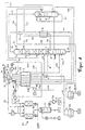
- air to be broken down is drawn in at 1 and in an air compressor 30 a first pressure, essentially medium pressure column pressure (plus line losses) compressed, pre-cooled in a cooling device 31 in direct contact with water and in a cleaning device (molecular sieve system) 32 in particular of water and Free of carbon dioxide.
- a first pressure essentially medium pressure column pressure (plus line losses) compressed, pre-cooled in a cooling device 31 in direct contact with water and in a cleaning device (molecular sieve system) 32 in particular of water and Free of carbon dioxide.
- the cleaned air is divided into three sub-streams, the first of which without further measures to increase pressure via line 103, through a main heat exchanger 2 and is introduced via line 104 into a medium pressure column 6.
- the medium pressure column 6 is - according to the respective product specification and the pressure loss - under operated at a pressure of 2 to 4 bar, preferably about 2.5 to 3.5 bar.
- the second partial flow of the cleaned air is in a post-compressor 202 essential pressure column pressure (plus line losses) compressed, in Main heat exchanger 2 in indirect heat exchange with cold process streams cooled to dew point temperature and introduced into the bottom of a pressure column 7 (see positions 201,202,203,2,204 and 7).
- the pressure column 7 is at one Working pressure of 5 to 10 bar, preferably operated 5.5 to 6.5 bar and is over a main capacitor 3 thermally coupled to a low pressure column 5.
- Latter works at a pressure of 1.1 to 2.0 bar, preferably 1.3 to 1.7 bar.
- the Air post-compressor 202 can be driven by the same motor shaft as that Air compressor 30.
- the third partial flow is fed via a line 301 to a compressor station 305 for Turbine air (306, 307, 308) into a turbine 309 and / or for rectification air (313, 314, 315), the intake pressure 303 using a throttle device 302 can be reduced especially in underload operation.
- the air of the third partial flow is about in the compression station 305
- Medium pressure column pressure compressed to a pressure equal to an air condensation temperature corresponds, which is at least approximately equal to Evaporation temperature of the liquid pressurized oxygen 17 is alternatively the third partial flow of the cleaned air also on the pressure side of the air post-compressor 202 are branched off when air (312) from the expansion turbine 309 is fed into the pressure column 7.
- the suction pressure of the compressor station 305 then corresponds to the pressure column pressure.
- a first portion 307 of the highly compressed air 306 is at a temperature 308 which between the temperatures at the warm and cold ends of the Main heat exchanger 2 is fed to the expansion turbine 309 and there for example, medium pressure column pressure relaxed while working.
- the embodiment is the turbine output by a brake generator to the The relaxed turbine outlet flow is partly through the Main heat exchanger 2 via lines 310,311 and 304 to the suction side of the Compressor station 305 returned, partly via line 312 in the bottom of the Medium pressure column 6 fed.
- a second part 313 of the highly compressed air 306 is against the evaporating Pressurized oxygen 17 at least partially, preferably completely or in essentially completely liquefied, to a part 314 above the sump in the Low pressure column 5 and another part 315 in the bottom of the pressure column 7 relaxed.
- Bottom liquid 70 and washing nitrogen 74 from the top of the pressure column 7 are in a supercooling counterflow 4 against a residual gas flow 50
- Low pressure column 5 supercooled and in each case in the low pressure column 5 and / or in the Medium pressure column relaxed (lines 71, 72, 73, 75, 76 and 77).
- Bottom liquid 60 and washing nitrogen 61 from the medium pressure column are also in the Subcooling countercurrent 4 subcooled against the residual gas stream 50 (not in Figure 1 shown) or the bottom liquid 60 directly into the top condenser 10 of the Medium pressure column and the washing nitrogen 61 on the head of the low pressure column 5 given up.
- a residual gas stream 51 and products from the rectification section, in Example GOX and DGOX are approximately in the main heat exchanger 2 Ambient temperature warmed up (lines 51, 52, 54, 55, 17 and 18).
- the Residual gas stream 52 can be completely or partially as stream 53 for the regeneration of the Molecular sieve station 32 can be used.
- Liquid oxygen 15 is taken from the bottom of the low pressure column, depending on Product specification with the help of an oxygen pump 16 to the required Delivery pressure compressed or completely or partially into a removable storage tank 80 filled.
- Liquid nitrogen 78 is drawn off from the top of the low pressure column 5 or branched off from one of the washing nitrogen lines 75 or 61 and likewise internally compressed (not shown in FIG. 1) or in a removable storage tank 79 fed.
- the compressor station 305 consists of at least two in parallel switched compressors. This makes it possible to also use the removable storage system to operate as a pure gas apparatus, i.e. without liquid production the to generate internally compressed oxygen (DGOX).
- DGOX internally compressed oxygen
- one of the two compressors of the compression station 305 is taken out of operation and the second compressor takes over the task of compressing the inside Evaporate pressurized oxygen 17.
- the compressor station 305 thus exists according to the invention from two compressors, each with a different function, from one for the generation of cold for liquid production and the other for Evaporation of the internally compressed oxygen is used.
- the removable storage tanks 79 and 80 are used in the example of a time-limited Overproduction of DGOX, the removal of LOX and LIN as sales products, as Emergency supply tanks, as removable storage of the LOX and LIN cold contents and as Cooling supply with the cooling circuit switched off.
- the compressor station shown in FIG. 1 can be single-stage or multi-stage machines with intercooling and / or aftercooling included.
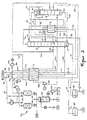
- the work output of the Expansion turbine 309 in the present embodiment to a booster transfer.
- the air throttle flow 313 is cooled in the Main heat exchanger 2 and subsequent isenthalpic relaxation in the Double column 5,7 compressed to a pressure which is at least as large as that Final pressure of the compressor station 305 of the exemplary embodiment in FIG. 1.
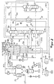
- air to be broken down is drawn in at 1 and in an air compressor 30 a first pressure, essentially medium pressure column pressure (plus line losses) compressed, pre-cooled in a cooling device 31 in direct contact with water and in a cleaning device (molecular sieve system) 32 in particular of water and Free of carbon dioxide.
- a first pressure essentially medium pressure column pressure (plus line losses) compressed, pre-cooled in a cooling device 31 in direct contact with water and in a cleaning device (molecular sieve system) 32 in particular of water and Free of carbon dioxide.
- the cleaned air is divided into three sub-streams, the first of which without further measures to increase pressure via line 103, through main heat exchanger 2 and can be introduced via line 104 into a medium pressure column 6.
- the Medium pressure column 6 is - according to the respective product specification and Pressure loss - under a pressure of 2 to 4 bar, preferably about 2.5 to 3.5 bar operated.
- the second partial flow of the cleaned air is applied to one in a post-compressor 202 Compresses pressure that corresponds to an air condensation temperature that at least approximately the same as the evaporation temperature of a liquid low-pressure oxygen 15 is, in the main heat exchanger 2 in indirect heat exchange with cold Process streams cooled and in a bottom condenser 3 of the low pressure column 5 introduced (see positions 201, 202, 203, 2, 204 and 3).
- the Air post-compressor 202 can be driven by the same motor shaft as that Air compressor 30.
- the two-column apparatus shown works with high oxygen purities (greater than 99.5%) in the limit case over into the normal double column apparatus (see e.g. patent DE 195 26 785 C1).
- the second partial flow then goes to zero and that Low pressure column taps of streams 62 and 63 shift towards the swamp the low pressure column 5, so that the top capacitor 10 to the main capacitor of the Double column is and the pressure of the medium pressure column corresponding to the thermal coupling increased
- the third partial flow is fed via a line 301 to a compressor station 305 for Turbine air (306, 307, 308) into a turbine 309 and / or for rectification air (313, 314, 315) supplied, the suction pressure 303 thereof with the aid of a throttle device 302 can be reduced in particular in underload operation.
- the air of the third Partial flow is in the compressor station 305 from about medium pressure column pressure compresses a pressure that corresponds to an air condensation temperature that at least approximately equal to the vaporization temperature of the liquid pressurized oxygen 17 is.
- a first partial stream 307 of the highly compressed air 306 is fed via line 308 to a Temperature that is between the temperatures at the warm and cold ends of the Main heat exchanger 2 is fed to the expansion turbine 309 and there for example, medium pressure column pressure relaxed while working.
- the embodiment is the turbine output by a brake generator to the The relaxed turbine outlet flow is partly through the Main heat exchanger 2 via lines 310,311 and 304 to the suction side of the Compressor station 305 returned, partly via line 312 in the bottom of the Medium pressure column 6 fed
- a second partial flow 313 of the highly compressed air 306 is against the evaporating pressurized oxygen 17 at least partially, preferably completely or essentially completely liquefied, to a part 314 above the sump in the low pressure column 5 and another part 315 in the swamp of the Medium pressure column 6 relaxed.
- Liquid oxygen 15 is taken from the bottom of the low pressure column, depending on Product specification with the help of an oxygen pump 16 to the required Delivery pressure compressed or completely or partially into a removable storage tank 80 filled.
- Liquid nitrogen 78 is drawn off from the top of the low pressure column 5 or branched off from the washing nitrogen line 61 and likewise internally compressed (in 1 not shown) or fed into the removable storage tank 79.
- the compressor station 305 consists of at least two in parallel switched compressors. This makes it possible to also use the removable storage system to operate as a pure gas apparatus, i.e. without liquid production the to generate internally compressed oxygen (DGOX).
- DGOX internally compressed oxygen
- one of the two compressors of the compression station 305 is taken out of operation and the second compressor takes over the task of compressing the inside Evaporate pressurized oxygen 17.
- the compressor station 305 thus exists according to the invention from two compressors, each with a different function, from one for the generation of cold for liquid production and the other for Evaporation of the internally compressed oxygen is used.
- the removable storage tanks 79 and 80 are used in the example of a time-limited Overproduction of DGOX, the removal of LOX and LIN as sales products, as Emergency supply tanks, as removable storage of the LOX and LIN cold contents and as Cooling supply with the cooling circuit switched off.
- the compressor station shown in FIG. 3 can be single-stage or multi-stage machines with intercooling and / or aftercooling included.
- the work performance of the Expansion turbine 309 in the present embodiment to a booster transfer.
- the air throttle flow 313 is cooled in the Main heat exchanger 2 and subsequent isenthalpic expansion into the columns 5 and 6 compressed to a pressure at least as large as the ultimate pressure of the Compressor station 305 of the exemplary embodiment in FIG. 3.
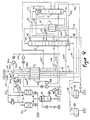
- the table shows the product flows, the alternating storage flows, for the (circulation and throttle air) compressor station the number of compressors in operation, the air flows and the energy requirements of the system. All gas and liquid flows are given in m 3 / h, whereby m 3 / h in the normal state are meant at 1atm and 273 K.
- the operating cases A1, A2 and A3 are characterized in that both compressors of the compressor station are in operation and supply a turbine flow and a throttle flow.
Abstract
Description
Die Erfindung betrifft ein Verfahren zur Erzeugung von gasförmigem Druckprodukt durch Tieftemperaturzerlegung von Luft, das zeitweise in einem Gasbetrieb und zeitweise in einem kombinierten Betrieb betrieben wird.The invention relates to a method for Generation of gaseous pressure product by low-temperature separation of air, at times in a gas operation and at times in a combined operation is operated.
Die Erfindung betrifft außerdem eine Vorrichtung zur Durchführung dieses Verfahrens. The invention also relates to an apparatus for performing this method.
Aus der Schrift EP 0 044 679 A1 ist ein Verfahren zur Erzeugung von gasförmigem Drucksauerstoff (DGOX) und geringer Mengen Flüssigsauerstoff (LOX) bekannt: Kälte für die Luftzerlegung und die Erzeugung von Flüssigprodukt liefert ein Luftkältekreislauf. Er enthält eine Verdichtung mit zwei Kompressorstufen in Serie zur Verdichtung eines Luftstromes in der ersten Stufe auf einen mittleren Druck für eine arbeitsleistende Entspannung eines Teilstromes dieser Luft auf einen unteren Druck und eine zweite Kompressorstufe zur Verdichtung des restlichen Luftstromes auf einen höheren Druck für eine Drosselentspannung auf den gleichen niedrigen Druck. Nach Zusammenführung der Teilströme und Abzweigen einer gebildeten Flüssigphase wird die Gasphase zur Verdichtung rezykliert und die Flüssigphase nach Aufteilung in zwei Drosselströme einer Rektifikation zugeführt. Der Kältekreislauf kann bei einem solchen Verfahren nicht abgeschaltet werden und ein Zurückfahren der Kälteleistung führt zu einem energetisch ungünstigen Betrieb.From the document EP 0 044 679 A1 is a process for the production of gaseous Compressed oxygen (DGOX) and small amounts of liquid oxygen (LOX) known: cold supplies for air separation and the production of liquid product Air cooling circuit. It contains a compression with two compressor stages in series Compression of an air flow in the first stage to a medium pressure for one work-relieving relaxation of a partial flow of this air to a lower pressure and a second compressor stage to compress the remaining air flow to one higher pressure for throttle relaxation to the same low pressure. To Merging the partial streams and branching off a liquid phase formed the gas phase recycles for compression and the liquid phase after splitting into two Choke currents fed to a rectification. The refrigeration cycle in such a The process cannot be switched off and the cooling capacity is reduced an energetically unfavorable operation.
Aufgabe der Erfindung ist ein Verfahren und eine Vorrichtung der eingangs genannten Art mit einer energetisch günstigen Erzeugung des gasförmigen Druckprodukts und des Flüssigprodukts jeweils in variablen Mengen und bei hoher Verfügbarkeit der Erzeugung des Druckprodukts.The object of the invention is a method and a device of the aforementioned Kind with an energetically favorable production of the gaseous printed product and of the liquid product in variable quantities and with high availability of the Generation of the printed product.
Diese Aufgabe wird erfindungsgemäß gelöst von einem Verfahren mit den Merkmalen
des Anspruchs 1 und von einer Vorrichtung mit den Merkmalen des Anspruchs 8.
Ausführungen der Erfindung sind Gegenstand von Unteransprüchen.According to the invention, this object is achieved by a method having the features
of
Kennzeichnend an dem erfindungsgemäßen Verfahren ist, daß beim Gasbetrieb der Luftdurchsatz im Kältekreislauf auf Null reduziert wird und zu einer Kompensation von Kälteverlusten, die nicht mehr durch den Kältekreislauf gedeckt werden, tiefkalte gespeicherte Flüssigkeit verwendet wird. Dies ermöglicht die Erzeugung von gasförmigem Druckprodukt auch bei vollem Flüssigprodukttank, indem beispielsweise gespeichertes Flüssigprodukt in einem Wärmeaustauscher im Gegenstrom zur eingesetzten Luft geführt wird, diese Luft dabei abgekühlt, teilweise verflüssigt und der Rektifikation zugeführt wird oder indem gespeicherte Flüssigkeit direkt der Rektifikation zugeführt wird.It is characteristic of the method according to the invention that the gas operation of the Air flow in the refrigeration circuit is reduced to zero and a compensation of Cold losses that are no longer covered by the refrigeration cycle are extremely cold stored liquid is used. This enables the generation of gaseous printed product even with a full liquid product tank, for example stored liquid product in a heat exchanger in counterflow to used air is guided, this air is cooled, partially liquefied and the Rectification is supplied or by stored liquid directly to the rectification is fed.
Tiefkalte Flüssigkeit mindestens einer flüssigen Fraktion aus der Rektifikation, beispielsweise Flüssigstickstoff (LIN), Flüssigsauerstoff (LOX) oder flüssige Luft, zur Kompensation von Kälteverlusten im Gasbetrieb kann in einem Tank zwischengespeichert werden, wobei als Tank zum Speichern dieser Fraktionen Pufferbehälter und/oder Produkttanks verwendet werden. Meist ist die Nutzung von Produkttanks die günstigste Lösung, während flüssige Luft eher einen Pufferbehälter erfordert, da flüssige Luft als Produkt meist keine Rolle spielt.Cryogenic liquid of at least one liquid fraction from the rectification, for example liquid nitrogen (LIN), liquid oxygen (LOX) or liquid air Compensation for cold losses in gas operation can be in a tank be cached, being used as a tank to store these fractions Buffer tanks and / or product tanks can be used. Most is the use of Product tanks are the cheapest solution, while liquid air is more like a buffer tank Required, since liquid air usually doesn't matter as a product.
Zeitweise kann unter Verwendung mindestens zweier Tanks eine Wechselspeicherung vorgenommen werden, wobei einerseits bei erhöhtem Drucksauerstoff (DGOX)-Bedarf zusätzlich zum LOX aus der Rektifikation aus dem einen Tank zwischengespeichertes LOX entnommen, verdichtet, im Gegenstrom verdampft und angewärmt und dann als DGOX-Produkt abgeben wird und hierbei im Gegenstrom Kälte zurückgewonnen und zur Erzeugung und Zwischenspeicherung von LIN-Produkt verwendet wird, wobei andererseits bei niedrigem DGOX-Bedarf entsprechend wenig LOX aus dem Rektifiziersystem als DGOX abgegeben und dafür mehr LOX zwischengespeichert wird. Der Vorteil besteht darin, daß zeitweise mehr DGOX geliefert wird als nach Auslegung der Luftzerlegung möglich wäre, indem gespeichertes LOX entnommen und dem Kälteinhalt des LOX entsprechend LIN gespeichert wird.Temporary storage can be used temporarily using at least two tanks be made, on the one hand with increased pressure oxygen (DGOX) demand in addition to the LOX from rectification from one tank LOX removed, compressed, evaporated in countercurrent and warmed and then as DGOX product is released and thereby recovered in countercurrent cold and is used to create and cache LIN product, where on the other hand, with low DGOX requirements, correspondingly little LOX from the Rectification system given as DGOX and more LOX temporarily stored becomes. The advantage is that sometimes more DGOX is delivered than to Interpretation of air separation would be possible by removing stored LOX and the cold content of the LOX is saved according to LIN.
Zur Rektifikation kann ein Zweisäulenverfahren eingesetzt werden, wobei eine Kopfkühlung der Drucksäule mit einer Zwischenflüssigkeit aus einer Niederdrucksäule bewerkstelligt und eine Sumpfheizung der Niederdrucksäule durch indirekten Wärmeaustausch mit Luft vorgenommen wird. Das Zweisäulenverfahren ist aus DE 196 09 490 A1 bekannt und eignet sich besonders, wenn nur eine geringe Sauerstoffreinheit erforderlich ist.A two-column process can be used for rectification, one Head cooling of the pressure column with an intermediate liquid from a low pressure column accomplished and a sump heating of the low pressure column by indirect Heat exchange with air is made. The two-column process is from DE 196 09 490 A1 and is particularly suitable if only a small one Oxygen purity is required.
Als Rektifiziersystem kann alternativ auch ein Dreisäulenverfahren eingesetzt werden, wobei eine Doppelsäule mit einem Hochdruckteil und einem Niederdruckteil und eine Zusatzsäule unter Zwischendruck eingesetzt wird. Das Dreisäulenverfahren ist aus DE 195 37 913 A1 bekannt. Auch bei Sauerstoffreinheiten > 99,5 mol % sind mit diesem Verfahren Energieeinsparungen möglich. Alternatively, a three-column process can also be used as the rectification system, being a double column with a high pressure part and a low pressure part and a Additional column is used under intermediate pressure. The three-column process is from DE 195 37 913 A1 known. Even with oxygen purities> 99.5 mol% are with this Process energy savings possible.
Bei der Gewinnung von gasförmigem Druckprodukt durch Verdampfen und Anwärmen von Flüssigkeit unter Druck, auch Innenverdichtung genannt, im Gegenstrom mit warmer Luft, kann Luft auf dem oberen Druckniveau der Verdichtung im Kältekreislauf verwendet werden oder solche, die von diesem Druckniveau ausgehend nachverdichtet wird.In the production of gaseous printed products by evaporation and heating of liquid under pressure, also called internal compression, in counterflow warm air, air can reach the upper pressure level of compression in the refrigeration cycle used or those based on this pressure level is densified.
Die arbeitsleistende Entspannung kann in mindestens einer Kälteturbine erfolgen, wobei die Leistung an der Welle einer solchen Turbine zum Antrieb entweder eines stromerzeugenden Generators oder eines Boosters verwendet wird, wobei der Booster beispielsweise zum Nachverdichten der Luft im Kältekreislauf eingesetzt wird. In beiden Fällen wird die Energie der Kälteturbine günstig genutzt.The work-relieving relaxation can take place in at least one cooling turbine, the power on the shaft of such a turbine for driving either one electricity generating generator or a booster is used, the booster is used, for example, to recompress the air in the refrigeration cycle. In In both cases, the energy of the cooling turbine is used cheaply.
Kennzeichnend an der erfindungsgemäßen Vorrichtung ist, daß die Verdichterstation mit mindestens zwei parallel angeordneten Verdichtem ausgeführt ist, die so ausgelegt sind, daß im Gasbetrieb nur einer der Verdichter in Betrieb ist, wobei dieser Verdichter Drosselluft liefert und der Kältekreislauf nicht mit Luft beaufschlagt ist, während im Betrieb mit Erzeugung von Druckprodukt und Flüssigprodukt mindestens zwei parallel angeordnete Verdichter in Betrieb sind und zusätzlich zum Liefern von Drosselluft auch der Kältekreislauf mit Luft beaufschlagt ist. Eine solche Verdichterstation besitzt mehrere Vorteile. Für den Gasbetrieb wird ein Verdichter an seinem energetisch günstigsten Betriebspunkt, bei zusätzlicher Erzeugung von Flüssigprodukt werden mehrere, beispielsweise zwei Verdichter nahe ihrem optimalen Betriebspunkt eingesetzt. Mit mehreren Verdichtem wird außerdem gleichzeitig eine Maschinenredundanz geschaffen, die die Versorgungssicherheit im Gasbetrieb entsprechend erhöht. Ein weiterer Vorteil der Erfindung besteht darin, daß mit einem Verdichter, als Kreislaufverdichter betrieben, auch energetisch günstig Flüssigprodukt erzeugt werden kann und daß dieser Flüssigbetrieb durch die Maschinenredundanz ebenfalls mit hoher Versorgungssicherheit ermöglicht wird.Characteristic of the device according to the invention is that the compressor station is designed with at least two compressors arranged in parallel, which are designed in this way are that only one of the compressors is in operation in gas operation, this compressor Throttle air supplies and the refrigeration circuit is not pressurized while in Operation with production of printed product and liquid product at least two in parallel arranged compressors are in operation and in addition to supplying throttle air the cooling circuit is pressurized with air. Such a compressor station has several advantages. A compressor is energetically connected to its gas operation cheapest operating point, with additional production of liquid product several, for example two compressors close to their optimal operating point used. With several compressors, one becomes simultaneously Machine redundancy created that ensures security of supply in gas operation increased accordingly. Another advantage of the invention is that with a Compressor, operated as a cycle compressor, also an energy-efficient liquid product can be generated and that this liquid operation through machine redundancy is also made possible with high security of supply.
Die Kälteturbine im Leitungsstrang des Kältekreislaufs kann als Turbinen/Generator-Einheit ausgebildet sein. Die in der Kälteturbine gewonnene Energie wird in das örtliche Stromnetz eingespeist. The refrigeration turbine in the refrigeration circuit wiring harness can function as a turbine / generator unit be trained. The energy gained in the cooling turbine is transferred to the local power grid fed.
Die Kälteturbine im Leitungstrang des Kältekreislaufs kann als Turbinen/Booster-Einheit ausgebildet sein, wobei der Booster im Leitungsstrang des Kältekreislaufs als Nachverdichter von Luft aus der Verdichterstation geschaltet ist Die in der Kälteturbine gewonnene Energie wird, beispielsweise über eine gemeinsame Welle mit einem Booster zum Antrieb dieses Boosters verwendet.The cooling turbine in the wiring harness of the cooling circuit can act as a turbine / booster unit be formed, the booster in the wiring harness of the refrigeration circuit as Post-compressor air is switched from the compressor station in the refrigeration turbine gained energy, for example via a common wave with a Booster used to drive this booster.
Im Leitungsstrang für die Drosselluft kann ein Nachverdichter für Luft aus der Verdichterstation angeordnet sein.A secondary compressor for air from the Compressor station can be arranged.
Eine vorteilhafte Anwendung erfährt das Verfahren und die Vorrichtung gemäß Erfindung in einer Luftzerlegungsanlage zur Belieferung eines Stahlwerks mit Stickstoff und Sauerstoff.The method and the device according to FIG Invention in an air separation plant for supplying a steel plant with nitrogen and oxygen.
Energetisch günstig kann mit hoher Versorgungssicherheit dem wechselnden Bedarf des Stahlwerks an gasförmigem Druckprodukt Rechnung getragen werden. Die Erfindung sowie weitere Ausgestaltungen der Erfindung werden im folgenden anhand von in den Zeichnungen dargestellten Ausführungsbeispielen näher erläutert.The changing demand can be energy-efficient with a high security of supply of the steelworks on gaseous printed products. The Invention and further refinements of the invention are described below of exemplary embodiments illustrated in the drawings.
Hierbei zeigen:
In Figur 1 wird zu zerlegende Luft bei 1 angesaugt und in einem Luftverdichter 30 auf
einen ersten Druck im wesentlichen Mitteldrucksäulendruck (plus Leitungsverluste)
verdichtet, in einer Kühleinrichtung 31 in direktem Kontakt mit Wasser vorgekühlt und
in einer Reinigungseinrichtung (Molsiebanlage) 32 insbesondere von Wasser und
Kohlendioxid befreit.In FIG. 1, air to be broken down is drawn in at 1 and in an air compressor 30
a first pressure, essentially medium pressure column pressure (plus line losses)
compressed, pre-cooled in a
Die gereinigte Luft wird in drei Teilströme aufgeteilt, von denen der erste ohne weitere
druckerhöhende Maßnahmen über Leitung 103, durch einen Hauptwärmetauscher 2
und über Leitung 104 in eine Mitteldrucksäule 6 eingeführt wird. Die Mitteldrucksäule 6
wird - entsprechend der jeweiligen Produktspezifikation und den Druckveriusten - unter
einem Druck von 2 bis 4 bar, vorzugsweise etwa 2,5 bis 3,5 bar betrieben.The cleaned air is divided into three sub-streams, the first of which without further
measures to increase pressure via
Der zweite Teilstrom der gereinigten Luft wird in einem Nachverdichter 202 auf im
wesentlichen Drucksäulendruck (plus Leitungsverluste) verdichtet, im
Hauptwärmetauscher 2 in indirektem Wärmeaustausch mit kalten Verfahrensströmen
auf Taupunktstemperatur abgekühlt und in den Sumpf einer Drucksäule 7 eingeführt
(siehe Positionen 201,202,203,2,204 und 7). Die Drucksäule 7 wird bei einem
Arbeitsdruck von 5 bis 10 bar, vorzugsweise 5,5 bis 6,5 bar betrieben und ist über
einen Hauptkondensator 3 mit einer Niederdrucksäule 5 thermisch gekoppelt. Letztere
arbeitet bei einem Druck von 1,1 bis 2,0 bar vorzugsweise 1,3 bis 1,7 bar. Der
Luftnachverdichter 202 kann von derselben Motorwelle angetrieben werden wie der
Luftverdichter 30.The second partial flow of the cleaned air is in a post-compressor 202
essential pressure column pressure (plus line losses) compressed, in
Der dritte Teilstrom wird über eine Leitung 301 einer Verdichterstation 305 für
Turbinenluft (306, 307, 308) in eine Turbine 309 und/oder für Rektifikationsluft (313,
314, 315) zugeführt, wobei der Ansaugdruck 303 mit Hilfe einer Drosselvorrichtung 302
vermindert werden kann insbesondere bei Unterlastbetrieb.The third partial flow is fed via a
Die Luft des dritten Teilstroms wird in der Verdichterstation 305 von etwa
Mitteldrucksäulendruck auf einen Druck komprimiert, der einer Luft-Kondensationstemperatur
entspricht, die mindestens etwa gleich der
Verdampfungstemperatur des flüssigen Drucksauerstoffs 17 ist Alternativ kann der
dritte Teilstrom der gereinigten Luft auch an der Druckseite des Luftnachverdichters
202 abgezweigt werden, wenn gleichzeitig Luft (312) aus der Entspannungsturbine 309
in die Drucksäule 7 eingespeist wird. Der Ansaugdruck der Verdichterstation 305
entspricht dann dem Drucksäulendruck. The air of the third partial flow is about in the
Ein erster Teil 307 der hochverdichteten Luft 306 wird bei einer Temperatur 308, die
zwischen den Temperaturen am warmen und am kalten Ende des
Hauptwärmetauschers 2 liegt, der Entspannungsturbine 309 zugeleitet und dort auf
etwa Mitteldrucksäulendruck arbeitsleistend entspannt. Im vorliegenden
Ausführungsbeispiel wird die Turbinenleistung durch einen Bremsgenerator an das
Werksnetz übertragen.Der entspannte Turbinenaustrittsstrom wird teils durch den
Hauptwärmetauscher 2 über die Leitungen 310,311 und 304 auf die Saugseite der
Verdichterstation 305 zurückgeführt, teils über Leitung 312 in den Sumpf der
Mitteldrucksäule 6 eingespeist.A
Ein zweiter Teil 313 der hochverdichteten Luft 306 wird gegen den verdampfenden
Drucksauerstoff 17 mindestens teilweise, vorzugsweise vollständig oder im
wesentlichen vollständig verflüssigt, zu einem Teil 314 oberhalb vom Sumpf in die
Niederdrucksäule 5 und zu einem anderen Teil 315 in den Sumpf der Drucksäule 7
entspannt.A
Sumpfflüssigkeit 70 und Waschstickstoff 74 vom Kopf der Drucksäule 7 werden in
einem Unterkühlungsgegenströmer 4 gegen einen Restgasstrom 50 der
Niederdrucksäule 5 unterkühlt und jeweils in die Niederdrucksäule 5 und / oder in die
Mitteldrucksäule entspannt (Leitungen 71,72,73,75,76 und 77). Sumpfflüssigkeit 60
und Waschstickstoff 61 aus der Mitteldrucksäule werden ebenfalls im
Unterkühlungsgegenströmer 4 gegen den Restgasstrom 50 unterkühlt (in Figur 1 nicht
dargestellt) oder die Sumpfflüssigkeit 60 direkt in den Kopfkondensator 10 der
Mitteldrucksäule und der Waschstickstoff 61 auf den Kopf der Niederdrucksäule 5
aufgegeben. Ein Restgasstrom 51 und Produkte aus dem Rektifikationsabschnitt, im
Beispiel GOX und DGOX werden im Hauptwärmetauscher 2 etwa auf
Umgebungstemperatur angewärmt (Leitungen 51, 52, 54, 55,17 und 18). Der
Restgasstrom 52 kann vollständig oder teilweise als Strom 53 zur Regenerierung der
Molekularsiebstation 32 eingesetzt werden.
Flüssiger Sauerstoff 15 wird dem Sumpf der Niederdrucksäule entnommen, je nach
Produktspezifikation mit Hilfe einer Sauerstoffpumpe 16 auf den geforderten
Abgabedruck komprimiert oder vollständig oder teilweise in einen Wechselpeichertank
80 eingefüllt. Flüssiger Stickstoff 78 wird vom Kopf der Niederdrucksäule 5 abgezogen
oder von einer der Waschstickstoffleitungen 75 bzw.61 abgezweigt und ebenfalls
innenverdichtet (in Figur 1 nicht dargestellt) oder in einen Wechselspeichertank 79
eingespeist.
Zur Erhöhung der Flexibilität der Fahrweise und der Verfügbarkeit der Druckprodukte,
im Beispiel des DGOX besteht die Verdichterstation 305 aus mindestens zwei parallel
geschalteten Verdichtem. Hierdurch wird es möglich, die Wechselspeicheranlage auch
als reinen Gaseapparat zu betreiben,d.h. ohne Flüssigproduktion weiterhin den
innenverdichteten Drucksauerstoff (DGOX) zu erzeugen. Im Fall von zwei Verdichtem
wird einer der beiden Verdichter der Verdichterstation 305 außer Betrieb genommen
und der zweite Verdichter übernimmt die Aufgabe, den innenverdichteten
Drucksauerstoff 17 zu verdampfen. Somit besteht die Verdichterstation 305
erfindungsgemäß aus zwei Verdichtern mit jeweils unterschiedlicher Funktion, von
denen der eine zur Erzeugung der Kälte für die Flüssigproduktion und der andere zur
Verdampfung des innenverdichteten Drucksauerstoffs herangezogen wird.To increase the flexibility of the driving style and the availability of the print products,
In the example of the DGOX, the
Die Wechselspeichertanks 79 und 80 dienen im Beispiel einer zeitlich begrenzten
Überproduktion von DGOX, der Entnahme von LOX und LIN als Verkaufsprodukte, als
Notversorgungstanks,als Wechselspeicherung der LOX - und LIN -Kälteinhalte und als
Kälteversorgung bei abgeschaltetem Kältekreislauf.
Die in Figur 1 angegebene Verdichterstation kann ein- oder mehr- stufige Maschinen
mit Zwischen- und / oder Nachkühlung enthalten.The
In Abweichung zum Ausführungsbeispiel in Figur 1 wird die Arbeitsleistung der
Entspannungsturbine 309 in der vorliegenden Ausführung an einen Booster
übertragen. Außerdem wird der Luftdrosselstrom 313 vor seiner Abkühlung im
Hauptwärmetauscher 2 und anschließender isenthalper Entspannung in die
Doppelsäule 5,7 auf einen Druck komprimiert, der mindestens so groß ist wie der
Enddruck der Verdichterstation 305 des Ausführungsbeispiels in Figur 1.In deviation from the exemplary embodiment in FIG. 1, the work output of the
In Figur 3 wird zu zerlegende Luft bei 1 angesaugt und in einem Luftverdichter 30 auf
einen ersten Druck im wesentlichen Mitteldrucksäulendruck (plus Leitungsverluste)
verdichtet, in einer Kühleinrichtung 31 in direktem Kontakt mit Wasser vorgekühlt und
in einer Reinigungseinrichtung (Molsiebanlage) 32 insbesondere von Wasser und
Kohlendioxid befreit.In FIG. 3, air to be broken down is drawn in at 1 and in an air compressor 30
a first pressure, essentially medium pressure column pressure (plus line losses)
compressed, pre-cooled in a
Die gereinigte Luft wird in drei Teilströme aufgeteilt, von denen der erste ohne weitere
druckerhöhende Maßnahmen über Leitung 103, durch Hauptwärmetauscher 2 und
über Leitung 104 in eine Mitteldrucksäule 6 eingeführt werden kann. Die
Mitteldrucksäule 6 wird - entsprechend der jeweiligen Produktspezifikation und den
Druckverfusten - unter einem Druck von 2 bis 4 bar, vorzugsweise etwa 2,5 bis 3,5 bar
betrieben.The cleaned air is divided into three sub-streams, the first of which without further
measures to increase pressure via
Der zweite Teilstrom der gereinigten Luft wird in einem Nachverdichter 202 auf einen
Druck verdichtet, der einer Luft-Kondensationstemperatur entspricht, die mindestens
etwa gleich der Verdampfungstemperatur eines flüssigen Niederdrucksauerstoffs 15
ist, im Hauptwärmetauscher 2 in indirektem Wärmeaustausch mit kalten
Verfahrensströmen abgekühlt und in einen Sumpfkondensator 3 der Niederdrucksäule
5 eingeführt (siehe Positionen
201, 202, 203, 2, 204 und 3).The second partial flow of the cleaned air is applied to one in a post-compressor 202
Compresses pressure that corresponds to an air condensation temperature that at least
approximately the same as the evaporation temperature of a liquid low-
Letztere arbeitet bei einem Druck von 1,1 bis 2,0 bar vorzugsweise 1,3 bis 1,7 bar. Der
Luftnachverdichter 202 kann von derselben Motorwelle angetrieben werden wie der
Luftverdichter 30.The latter works at a pressure of 1.1 to 2.0 bar, preferably 1.3 to 1.7 bar. The
Air post-compressor 202 can be driven by the same motor shaft as that
Bei hohen Sauerstoffreinheiten (größer 99,5 % ) geht der gezeigte Zweisäulenapparat
im Grenzfall über in den normalen Doppelsäulenapparat (siehe z.B. Patentschrift DE
195 26 785 C1). Der zweite Teilstrom geht dann gegen Null und die
Niederdrucksäulenanstiche der Ströme 62 und 63 verschieben sich in Richtung Sumpf
der Niederdrucksäule 5, so daß der Kopfkondensator 10 zum Hauptkondensator der
Doppelsäule wird und sich der Druck der Mitteldrucksäule entsprechend der
thermischen Kopplung erhöhtThe two-column apparatus shown works with high oxygen purities (greater than 99.5%)
in the limit case over into the normal double column apparatus (see e.g. patent DE
195 26 785 C1). The second partial flow then goes to zero and that
Low pressure column taps of
Der dritte Teilstrom wird über eine Leitung 301 einer Verdichterstation 305 für
Turbinenluft (306, 307, 308) in eine Turbine 309 und/oder für Rektifikationsluft (313,
314, 315) zugeführt, wobei deren Ansaugdruck 303 mit Hilfe einer Drosselvorrichtung
302 vermindert werden kann insbesondere bei Unterlastbetrieb. Die Luft des dritten
Teilstromes wird in der Verdichterstation 305 von etwa Mitteldrucksäulendruck auf
einen Druck komprimiert, der einer Luft-Kondensationstemperatur entspricht, die
mindestens etwa gleich der Verdampfungstemperatur des flüssigen Drucksauerstoffs
17 ist.The third partial flow is fed via a
Ein erster Teilstrom 307 der hochverdichteten Luft 306 wird über Leitung 308 bei einer
Temperatur, die zwischen den Temperaturen am warmen und am kalten Ende des
Hauptwärmetauschers 2 liegt, der Entspannungsturbine 309 zugeleitet und dort auf
etwa Mitteldrucksäulendruck arbeitsleistend entspannt. Im vorliegenden
Ausführungsbeispiel wird die Turbinenleistung durch einen Bremsgenerator an das
Werksnetz übertragen.Der entspannte Turbinenaustrittsstrom wird teils durch den
Hauptwärmetauscher 2 über die Leitungen 310,311 und 304 auf die Saugseite der
Verdichterstation 305 zurückgeführt, teils über Leitung 312 in den Sumpf der
Mitteldrucksäule 6 eingespeistA first
Ein zweiter Teilstrom 313 der hochverdichteten Luft 306 wird gegen den
verdampfenden Drucksauerstoff 17 mindestens teilweise, vorzugsweise vollständig
oder im wesentlichen vollständig verflüssigt, zu einem Teil 314 oberhalb vom Sumpf in
die Niederdrucksäule 5 und zu einem anderen Teil 315 in den Sumpf der
Mitteldrucksäule 6 entspannt.A second
Sumpfflüssigkeit 60 und Waschstickstoff 61 vom Kopfkondensator 10 der
Mitteldrucksäule 6 werden in einem Unterkühlungsgegenströmer 4 gegen einen
Restgasstrom 50 der Niederdrucksäule 5 unterkühlt und jeweils in diese entspannt
(Leitungen 71,75 und 76). Ein Restgasstrom 51 und Produkte aus dem
Rektifikationsabschnitt, im Beispiel DGOX werden im Hauptwärmetauscher 2 etwa auf
Umgebungstemperatur angewärmt (Leitungen 51,52,17 und 18). Der Restgasstrom 52
kann vollständig oder teilweise zur Regenerierung 53 der Molekularsiebstation 32
eingesetzt werden.
Flüssiger Sauerstoff 15 wird dem Sumpf der Niederdrucksäule entnommen, je nach
Produktspezifikation mit Hilfe einer Sauerstoffpumpe 16 auf den geforderten
Abgabedruck komprimiert oder vollständig oder teilweise in einen Wechselpeichertank
80 eingefüllt. Flüssiger Stickstoff 78 wird vom Kopf der Niederdrucksäule 5 abgezogen
oder von der Waschstickstoffleitung 61 abgezweigt und ebenfalls innenverdichtet (in
Figur 1 nicht dargestellt) oder in den Wechselspeichertank 79 eingespeist.
Zur Erhöhung der Flexibilität der Fahrweise und der Verfügbarkeit der Druckprodukte,
im Beispiel des DGOX besteht die Verdichterstation 305 aus mindestens zwei parallel
geschalteten Verdichtem. Hierdurch wird es möglich, die Wechselspeicheranlage auch
als reinen Gaseapparat zu betreiben,d.h. ohne Flüssigproduktion weiterhin den
innenverdichteten Drucksauerstoff (DGOX) zu erzeugen. Im Fall von zwei Verdichtem
wird einer der beiden Verdichter der Verdichterstation 305 außer Betrieb genommen
und der zweite Verdichter übernimmt die Aufgabe, den innenverdichteten
Drucksauerstoff 17 zu verdampfen. Somit besteht die Verdichterstation 305
erfindungsgemäß aus zwei Verdichtern mit jeweils unterschiedlicher Funktion, von
denen der eine zur Erzeugung der Kälte für die Flüssigproduktion und der andere zur
Verdampfung des innenverdichteten Drucksauerstoffs herangezogen wird.To increase the flexibility of the driving style and the availability of the print products,
In the example of the DGOX, the
Die Wechselspeichertanks 79 und 80 dienen im Beispiel einer zeitlich begrenzten
Überproduktion von DGOX, der Entnahme von LOX und LIN als Verkaufsprodukte, als
Notversorgungstanks,als Wechselspeicherung der LOX - und LIN -Kälteinhalte und als
Kälteversorgung bei abgeschaltetem Kältekreislauf.
Die in Figur 3 angegebene Verdichterstation kann ein- oder mehr- stufige Maschinen
mit Zwischen- und / oder Nachkühlung enthalten.The
In Abweichung zum Ausführungsbeispiel 3 wird die Arbeitsleistung der
Entspannungsturbine 309 in der vorliegenden Ausführung an einen Booster
übertragen. Außerdem wird der Luftdrosselstrom 313 vor seiner Abkühlung im
Hauptwärmetauscher 2 und anschließender isenthalper Entspannung in die Säulen 5
und 6 auf einen Druck komprimiert, der mindestens so groß ist wie der Enddruck der
Verdichterstation 305 des Ausführungsbeispiel in Figur 3.In deviation from
Für die Belieferung eines Stahlwerks werden stark schwankende Mengen DGOX und Druckstickstoff (DRGAN) benötigt. Für die Belieferung des Gasmarktes sollen zusätzlich die Flüssigprodukte LOX, LIN und Flüssigargon (LAR) produziert werden, um die Wirtschaftlichkeit der Produktionsanlage zu erhöhen. Die Investitionsentscheidung wird zugunsten einer Anlage mit Turbinen/Booster-Einheit und Doppelsäulenrektifikation gefällt, weil keine Energie ins örtliche Stromnetz eingespeist werden darf und weil eine hohe Sauerstoffreinheit gefordert wird. Bis auf die nicht dargestellte Argongewinnung entspricht dies einer Anlage, wie sie in Figur 4 dargestellt ist. Die Tabelle zeigt für vier Hauptbetriebsarten A1, A2, A3 und A4 der Anlage die Produktströme, die Wechselspeicherströme, für die (Kreislauf- und Drosselluft-) Verdichterstation die Anzahl der im Betrieb befindlichen Kompressoren, die Luftströme und den Energiebedarf der Anlage. Alle Gas- und Flüssigkeitsströme sind in m3/h angegeben, wobei jeweils m3/h im Normalzustand bei 1atm und 273 K gemeint sind. Die Betriebsfälle A1, A2 und A3 zeichnen sich dadurch aus, daß beide Kompressoren der Verdichterstation in Betrieb sind und einen Turbinenstrom und einen Drosselstrom liefem.Strongly fluctuating amounts of DGOX and pressure nitrogen (DRGAN) are required to supply a steel mill. To supply the gas market, the liquid products LOX, LIN and Liquid Argon (LAR) are also to be produced in order to increase the efficiency of the production plant. The investment decision is made in favor of a plant with a turbine / booster unit and double-column rectification because no energy may be fed into the local power grid and because a high level of oxygen purity is required. Except for the argon production, which is not shown, this corresponds to a plant as shown in FIG. For four main operating modes A1, A2, A3 and A4 of the system, the table shows the product flows, the alternating storage flows, for the (circulation and throttle air) compressor station the number of compressors in operation, the air flows and the energy requirements of the system. All gas and liquid flows are given in m 3 / h, whereby m 3 / h in the normal state are meant at 1atm and 273 K. The operating cases A1, A2 and A3 are characterized in that both compressors of the compressor station are in operation and supply a turbine flow and a throttle flow.
Im Betriebsfall A1 werden zusätzlich zur Flüssigproduktion 10.000 m3/h DGOX erzeugt. Für eine Belieferung des Stahlwerks mit 13.000 m3/h DGOX wie in Betriebsfall A2 werden zusätzlich 3000 m3/h als LOX einem LOX-Tank flüssig entnommen und innenverdichtet als DGOX abgegeben. Der Kälteinhalt des LOX wird genutzt und reicht aus, um den LIN Tank mit 2.800 m3/h zu füllen. Im Betriebsfall A3 werden nur 7.000 m3/h DGOX an das Stahlwerk abgegeben. Der beispielsweise im Betriebsfall A2 entleerte LOX-Tank wird mit 3000 m3/h LOX wieder befüllt Die hierzu benötigte Kälte wird mit LIN aus dem vom Betriebsfall A2 her gefüllten LIN-Tank zugeführt.In operation A1, 10,000 m 3 / h DGOX are generated in addition to liquid production. In order to supply the steelworks with 13,000 m 3 / h DGOX as in operating case A2, an additional 3000 m 3 / h as LOX are removed from a LOX tank in liquid form and released internally compressed as DGOX. The cold content of the LOX is used and is sufficient to fill the LIN tank with 2,800 m 3 / h. In operation A3, only 7,000 m 3 / h DGOX are released to the steelworks. The LOX tank, for example emptied in operating case A2, is refilled with 3000 m 3 / h LOX. The cold required for this is supplied with LIN from the LIN tank filled in operating case A2.
Im Betriebsfall A4 ist in der Verdichterstation nur ein Kompressor in Betrieb. Er liefert
den Drosselstrom, Flüssigkeit wird nicht erzeugt. Selbst für die im Stahlwerk maximal
benötigte DGOX Menge von 13.000 m3/h ist die hierfür benötige Kälteleistung um eine
Größenanordnung kleiner als in den Betriebsfällen A1, A2 und A3, der äquivalent
benötigte Turbinenstrom müßte nur 4000 m3/h betragen. Der Kältekreislauf der Anlage
wird deshalb günstig durch Flüssigkeit aus den Tanks gedeckt und der Turbinenstrom
abgeschaltet. Andere Betriebsfälle sind denkbar. Die genannten Betriebsfälle zeichnen
sich dadurch besonders aus, daß alle betrieblichen Anforderungen energetisch günstig
erfüllt werden, weil die Maschinen in ihrem Auslegungspunkt bei etwa 100 % Leistung
betrieben werden. Der Stromverbrauch der Anlage ist in der überwiegenden Zeit
nahezu konstant. Deshalb kann bei den Elektroversorgungsuntemehmen ein günstiger
Stromtarif erzielt werden.
Claims (12)
- Process for producing gaseous pressurized product by low-temperature fractionation of air which is operated at times in a gas mode and at times in a combined mode,
in which process, in the gas mode and in the combined modein which process, in combined mode, gaseous pressurized product and liquid product are obtained, andcleaned charge air is cooled under excess pressure, is partially liquefied and is subjected to rectification in order to obtain gaseous and liquid fractions,cryogenic liquid from at least one of the liquid fractions from the rectification is evaporated under elevated pressure by indirect heat exchange with charge air, is heated and is obtained as gaseous pressurized product,and in which process in gas mode the air throughput in the refrigeration circuit is reduced to zero, and cryogenic stored liquid is used to compensate for refrigeration losses which are no longer covered by the refrigeration circuit.the refrigeration required to achieve this is generated in an air refrigeration circuit as a result of air being compressed in the refrigeration circuit and expanded in a work-performing manner, in the process heat is extracted from the air, and the air which has undergone work-performing expansion is at least in part heated again in countercurrent with the charge air which is to be cooled and is then recompressed,cryogenic liquid is produced by rectification and is at least partially stored, - Process according to Claim 1, characterized in that cryogenic liquid from at least one liquid fraction from the rectification, for example liquid nitrogen (LIN), liquid oxygen (LOX) or liquid air, is temporarily stored in a tank in order to compensate for refrigeration losses in gas mode, buffer vessels and/or product tanks being used as the tank for storing these fractions.
- Process according to Claim 1, characterized in that from time to time, using at least two tanks, alternating storage is carried out, in which, on the one hand, when there is a high demand for pressurized oxygen (DGOX), in addition to the LOX from the rectification, temporarily stored LOX is removed from one tank, compressed, evaporated in countercurrent and heated, and is then released as DGOX product, and in the process, in countercurrent. refrigeration is recovered and used to produce and temporarily store LIN product, and in which, on the other hand, when there is a low DGOX demand, correspondingly small amounts of LOX are released from the rectification system as DGOX, and correspondingly more LOX is temporarily stored.
- Process according to one of Claims 1 to 3, characterized in that a two-column process is used, in which top cooling of the pressure column is effected using an intermediate liquid from a low-pressure column, and bottom heating of the low-pressure column is carried out by indirect heat exchange with air.
- Process according to one of Claims 1 to 3, characterized in that a three-column process is used as the rectification system, using a double column with a high-pressure part and a low-pressure part and an additional column under intermediate pressure.
- Process according to one of Claims 1 to 5, characterized in that air from the refrigeration circuit downstream of the compression or air which has been recompressed downstream of the compression is used as charge air which is brought into indirect heat exchange with the evaporating cryogenic liquid from which the gaseous pressure product is obtained.
- Process according to one of Claims 1 to 6, characterized in that the work-performing expansion takes place in at least one refrigeration turbine, the output at the shaft of a turbine of this type being used to drive either a current-generating generator or a booster, the booster being used, for example, for recompression of the air in the refrigeration circuit.
- Apparatus for carrying out the process according to one of Claims 1 to 7, havingand in which apparatus the compressor station is designed with at least two compressors which are arranged in parallel and are designed in such a way that, in gas mode, only one of the compressors is operating, this compressor supplying throttled air, and the refrigeration circuit is not exposed to air, while in combined mode with production of pressurized product and liquid product, at least two compressors which are arranged in parallel are operating and, in addition, in order to supply throttled air, the refrigeration circuit is also acted on by air, and that the apparatus has means for storing liquid product.a main compressor for charge air, the exit pressure of the main air compressor also being the working pressure of a subsequent cleaning unit,a clean-air line leading from the cleaning unit to a compressor station for the air in the refrigeration circuit and for the air for rectification,and a pressure-side line from the compressor station which on one side opens out into a system of lines of the refrigeration circuit with at least one refrigeration turbine and on the other side opens out into a branch for passing throttled air to the columns,
- Apparatus according to Claim 8, characterized in that the refrigeration turbine in the system of lines of the refrigeration circuit is designed as a turbine/generator unit.
- Apparatus according to Claim 8, characterized in that the refrigeration turbine in the line section of the refrigeration circuit is designed as a turbine/booster unit, the booster in the system of lines of the refrigeration circuit being connected as a recompressor for air from the compressor station.
- Apparatus according to Claim 8 or 9, characterized in that a recompressor for air from the compressor station is arranged in the system of lines for the throttled air.
- Use of the process according to one of Claims 1 to 7 and of the apparatus according to one of Claims 8 to 11 in an air fractionation installation for supplying a steelworks with nitrogen and oxygen.
Priority Applications (1)
| Application Number | Priority Date | Filing Date | Title |
|---|---|---|---|
| EP19990106715 EP0949471B1 (en) | 1998-04-08 | 1999-04-01 | Cryogenic air separation plant with two different operation modes |
Applications Claiming Priority (5)
| Application Number | Priority Date | Filing Date | Title |
|---|---|---|---|
| DE1998115885 DE19815885A1 (en) | 1998-04-08 | 1998-04-08 | Air separation method producing gas, or gas and liquid e.g. for steel plant |
| DE19815885 | 1998-04-08 | ||
| EP98112276 | 1998-07-02 | ||
| EP98112276 | 1998-07-02 | ||
| EP19990106715 EP0949471B1 (en) | 1998-04-08 | 1999-04-01 | Cryogenic air separation plant with two different operation modes |
Publications (2)
| Publication Number | Publication Date |
|---|---|
| EP0949471A1 EP0949471A1 (en) | 1999-10-13 |
| EP0949471B1 true EP0949471B1 (en) | 2002-12-18 |
Family
ID=7864076
Family Applications (1)
| Application Number | Title | Priority Date | Filing Date |
|---|---|---|---|
| EP19990106715 Expired - Lifetime EP0949471B1 (en) | 1998-04-08 | 1999-04-01 | Cryogenic air separation plant with two different operation modes |
Country Status (7)
| Country | Link |
|---|---|
| US (1) | US6185960B1 (en) |
| EP (1) | EP0949471B1 (en) |
| AT (1) | ATE230098T1 (en) |
| CZ (1) | CZ297724B6 (en) |
| DE (1) | DE19815885A1 (en) |
| HU (1) | HUP9900988A2 (en) |
| PL (1) | PL191500B1 (en) |
Cited By (19)
| Publication number | Priority date | Publication date | Assignee | Title |
|---|---|---|---|---|
| DE102007031759A1 (en) | 2007-07-07 | 2009-01-08 | Linde Ag | Method and apparatus for producing gaseous pressure product by cryogenic separation of air |
| DE102007031765A1 (en) | 2007-07-07 | 2009-01-08 | Linde Ag | Process for the cryogenic separation of air |
| DE102009034979A1 (en) | 2009-04-28 | 2010-11-04 | Linde Aktiengesellschaft | Method for producing pressurized oxygen by evaporating liquid oxygen using a copper and nickel heat exchanger block |
| EP2312248A1 (en) | 2009-10-07 | 2011-04-20 | Linde Aktiengesellschaft | Method and device for obtaining pressurised oxygen and krypton/xenon |
| EP2458311A1 (en) | 2010-11-25 | 2012-05-30 | Linde Aktiengesellschaft | Method and device for creating a gaseous, pressurised product by the cryogenic decomposition of air |
| DE102010052544A1 (en) | 2010-11-25 | 2012-05-31 | Linde Ag | Process for obtaining a gaseous product by cryogenic separation of air |
| EP2520886A1 (en) | 2011-05-05 | 2012-11-07 | Linde AG | Method and device for creating gaseous oxygen pressurised product by the cryogenic decomposition of air |
| EP2568242A1 (en) | 2011-09-08 | 2013-03-13 | Linde Aktiengesellschaft | Method and device for generating of steel |
| EP2600090A1 (en) | 2011-12-01 | 2013-06-05 | Linde Aktiengesellschaft | Method and device for generating pressurised oxygen by cryogenic decomposition of air |
| DE102011121314A1 (en) | 2011-12-16 | 2013-06-20 | Linde Aktiengesellschaft | Method for producing gaseous oxygen product in main heat exchanger system in distillation column system, involves providing turbines, where one of turbines drives compressor, and other turbine drives generator |
| DE102013017590A1 (en) | 2013-10-22 | 2014-01-02 | Linde Aktiengesellschaft | Method for recovering methane-poor fluids in liquid air separation system to manufacture air product, involves vaporizing oxygen, krypton and xenon containing sump liquid in low pressure column by using multi-storey bath vaporizer |
| DE102012017488A1 (en) | 2012-09-04 | 2014-03-06 | Linde Aktiengesellschaft | Method for building air separation plant, involves selecting air separation modules on basis of product specification of module set with different air pressure requirements |
| EP2784420A1 (en) | 2013-03-26 | 2014-10-01 | Linde Aktiengesellschaft | Method for air separation and air separation plant |
| WO2014154339A2 (en) | 2013-03-26 | 2014-10-02 | Linde Aktiengesellschaft | Method for air separation and air separation plant |
| EP2801777A1 (en) | 2013-05-08 | 2014-11-12 | Linde Aktiengesellschaft | Air separation plant with main compressor drive |
| EP2963367A1 (en) | 2014-07-05 | 2016-01-06 | Linde Aktiengesellschaft | Method and device for cryogenic air separation with variable power consumption |
| EP2963370A1 (en) | 2014-07-05 | 2016-01-06 | Linde Aktiengesellschaft | Method and device for the cryogenic decomposition of air |
| EP2963371A1 (en) | 2014-07-05 | 2016-01-06 | Linde Aktiengesellschaft | Method and device for creating a pressurised gas product by the cryogenic decomposition of air |
| EP2963369A1 (en) | 2014-07-05 | 2016-01-06 | Linde Aktiengesellschaft | Method and device for the cryogenic decomposition of air |
Families Citing this family (30)
| Publication number | Priority date | Publication date | Assignee | Title |
|---|---|---|---|---|
| GB0002084D0 (en) * | 2000-01-28 | 2000-03-22 | Boc Group Plc | Air separation method |
| DE10015602A1 (en) * | 2000-03-29 | 2001-10-04 | Linde Ag | Method and device for obtaining a printed product by low-temperature separation of air |
| US6438990B1 (en) * | 2000-06-12 | 2002-08-27 | Jay K. Hertling | Refrigeration system |
| EP1207362A1 (en) * | 2000-10-23 | 2002-05-22 | Air Products And Chemicals, Inc. | Process and apparatus for the production of low pressure gaseous oxygen |
| DE10103968A1 (en) * | 2001-01-30 | 2002-08-01 | Linde Ag | Three-pillar system for the low-temperature separation of air |
| DE10111428A1 (en) * | 2001-03-09 | 2002-09-12 | Linde Ag | Method and device for separating a gas mixture with emergency operation |
| FR2831249A1 (en) * | 2002-01-21 | 2003-04-25 | Air Liquide | Air separation in an apparatus containing at least two columns which can be operated normally or with air expanded to a low pressure in the turbine before distillation in the low pressure column |
| FR2844344B1 (en) * | 2002-09-11 | 2005-04-08 | Air Liquide | PLANT FOR PRODUCTION OF LARGE QUANTITIES OF OXYGEN AND / OR NITROGEN |
| DE10249383A1 (en) * | 2002-10-23 | 2004-05-06 | Linde Ag | Method and device for the variable generation of oxygen by low-temperature separation of air |
| FR2854682B1 (en) * | 2003-05-05 | 2005-06-17 | Air Liquide | METHOD AND INSTALLATION OF AIR SEPARATION BY CRYOGENIC DISTILLATION |
| EP1582830A1 (en) * | 2004-03-29 | 2005-10-05 | Air Products And Chemicals, Inc. | Process and apparatus for the cryogenic separation of air |
| DE102004016931A1 (en) * | 2004-04-06 | 2005-10-27 | Linde Ag | Method and apparatus for variably producing a printed product by cryogenic separation of air |
| US7272954B2 (en) * | 2004-07-14 | 2007-09-25 | L'air Liquide, Societe Anonyme A Directoire Et Conseil De Surveillance Pour L'etude Et L'exploitation Des Proceded Georges Claude | Low temperature air separation process for producing pressurized gaseous product |
| US7263859B2 (en) * | 2004-12-27 | 2007-09-04 | L'air Liquide, Societe Anonyme A Directoire Et Conseil De Surveillance Pour L'etude Et L'exploitation Des Procedes Georges Claude | Process and apparatus for cooling a stream of compressed air |
| JP5005894B2 (en) * | 2005-06-23 | 2012-08-22 | エア・ウォーター株式会社 | Nitrogen generation method and apparatus used therefor |
| US20070251267A1 (en) * | 2006-04-26 | 2007-11-01 | Bao Ha | Cryogenic Air Separation Process |
| US20080289350A1 (en) * | 2006-11-13 | 2008-11-27 | Hussmann Corporation | Two stage transcritical refrigeration system |
| US20080115531A1 (en) * | 2006-11-16 | 2008-05-22 | Bao Ha | Cryogenic Air Separation Process and Apparatus |
| DE102007051184A1 (en) * | 2007-10-25 | 2009-04-30 | Linde Aktiengesellschaft | Method and apparatus for cryogenic air separation |
| DE102007051183A1 (en) * | 2007-10-25 | 2009-04-30 | Linde Aktiengesellschaft | Method for cryogenic air separation |
| DE102009023900A1 (en) | 2009-06-04 | 2010-12-09 | Linde Aktiengesellschaft | Method for cryogenic separation of air with distillation column system for nitrogen-oxygen separation, involves producing oxygen-enriched fraction and nitrogen fraction in high pressure column, and supplying nitrogen to low pressure column |
| CN102032755A (en) * | 2010-08-03 | 2011-04-27 | 苏州制氧机有限责任公司 | Air separation device |
| CN102072612B (en) * | 2010-10-19 | 2013-05-29 | 上海加力气体有限公司 | N-type pattern energy-saving gas manufacturing method |
| CN105143801A (en) * | 2013-03-28 | 2015-12-09 | 林德股份公司 | Method and device for producing gaseous compressed oxygen having variable power consumption |
| EP2824407A1 (en) * | 2013-07-11 | 2015-01-14 | Linde Aktiengesellschaft | Method for generating at least one air product, air separation plant, method and device for generating electrical energy |
| PL3410050T3 (en) * | 2017-06-02 | 2019-10-31 | Linde Ag | Method for producing one or more air products and air separation system |
| WO2020074120A1 (en) | 2018-10-09 | 2020-04-16 | Linde Aktiengesellschaft | Method for obtaining one or more air products and air separation system |
| US10914517B2 (en) * | 2018-11-16 | 2021-02-09 | L'air Liquide Societe Anonyme Pour L'etude Et L'exploitation Des Procedes Georges Claude | Method for utilizing waste air to improve the capacity of an existing air separation unit |
| CN110608583B (en) * | 2019-09-12 | 2021-07-23 | 北京首钢股份有限公司 | Pressure control method and device |
| CN113686099B (en) * | 2021-08-09 | 2022-08-09 | 北京科技大学 | Material recovery method based on internal compression air separation energy storage device |
Family Cites Families (8)
| Publication number | Priority date | Publication date | Assignee | Title |
|---|---|---|---|---|
| CS184647B1 (en) * | 1976-09-29 | 1978-08-31 | Jiri Sykora | Method of and apparatus for manufacturing liquid air separation products and pressurized oxygen |
| GB2080929B (en) * | 1980-07-22 | 1984-02-08 | Air Prod & Chem | Producing gaseous oxygen |
| DE3913880A1 (en) * | 1989-04-27 | 1990-10-31 | Linde Ag | METHOD AND DEVICE FOR DEEP TEMPERATURE DISPOSAL OF AIR |
| FR2701553B1 (en) * | 1993-02-12 | 1995-04-28 | Maurice Grenier | Method and installation for producing oxygen under pressure. |
| FR2704632B1 (en) * | 1993-04-29 | 1995-06-23 | Air Liquide | PROCESS AND PLANT FOR SEPARATING AIR. |
| FR2706195B1 (en) * | 1993-06-07 | 1995-07-28 | Air Liquide | Method and unit for supplying pressurized gas to an installation consuming an air component. |
| US5666823A (en) * | 1996-01-31 | 1997-09-16 | Air Products And Chemicals, Inc. | High pressure combustion turbine and air separation system integration |
| US5678425A (en) * | 1996-06-07 | 1997-10-21 | Air Products And Chemicals, Inc. | Method and apparatus for producing liquid products from air in various proportions |
-
1998
- 1998-04-08 DE DE1998115885 patent/DE19815885A1/en not_active Withdrawn
-
1999
- 1999-04-01 AT AT99106715T patent/ATE230098T1/en active
- 1999-04-01 EP EP19990106715 patent/EP0949471B1/en not_active Expired - Lifetime
- 1999-04-07 CZ CZ0121399A patent/CZ297724B6/en not_active IP Right Cessation
- 1999-04-07 PL PL332409A patent/PL191500B1/en unknown
- 1999-04-08 US US09/288,226 patent/US6185960B1/en not_active Expired - Fee Related
- 1999-04-08 HU HU9900988A patent/HUP9900988A2/en unknown
Cited By (25)
| Publication number | Priority date | Publication date | Assignee | Title |
|---|---|---|---|---|
| DE102007031759A1 (en) | 2007-07-07 | 2009-01-08 | Linde Ag | Method and apparatus for producing gaseous pressure product by cryogenic separation of air |
| DE102007031765A1 (en) | 2007-07-07 | 2009-01-08 | Linde Ag | Process for the cryogenic separation of air |
| EP2015013A2 (en) | 2007-07-07 | 2009-01-14 | Linde Aktiengesellschaft | Process and device for producing a gaseous pressurised product by cryogenic separation of air |
| EP2015012A2 (en) | 2007-07-07 | 2009-01-14 | Linde Aktiengesellschaft | Process for the cryogenic separation of air |
| DE102009034979A1 (en) | 2009-04-28 | 2010-11-04 | Linde Aktiengesellschaft | Method for producing pressurized oxygen by evaporating liquid oxygen using a copper and nickel heat exchanger block |
| EP2312248A1 (en) | 2009-10-07 | 2011-04-20 | Linde Aktiengesellschaft | Method and device for obtaining pressurised oxygen and krypton/xenon |
| EP2458311A1 (en) | 2010-11-25 | 2012-05-30 | Linde Aktiengesellschaft | Method and device for creating a gaseous, pressurised product by the cryogenic decomposition of air |
| DE102010052544A1 (en) | 2010-11-25 | 2012-05-31 | Linde Ag | Process for obtaining a gaseous product by cryogenic separation of air |
| DE102010052545A1 (en) | 2010-11-25 | 2012-05-31 | Linde Aktiengesellschaft | Method and apparatus for recovering a gaseous product by cryogenic separation of air |
| EP2466236A1 (en) | 2010-11-25 | 2012-06-20 | Linde Aktiengesellschaft | Method and device for creating a gaseous, pressurised product by the cryogenic decomposition of air |
| EP2520886A1 (en) | 2011-05-05 | 2012-11-07 | Linde AG | Method and device for creating gaseous oxygen pressurised product by the cryogenic decomposition of air |
| DE102011112909A1 (en) | 2011-09-08 | 2013-03-14 | Linde Aktiengesellschaft | Process and apparatus for recovering steel |
| EP2568242A1 (en) | 2011-09-08 | 2013-03-13 | Linde Aktiengesellschaft | Method and device for generating of steel |
| EP2600090A1 (en) | 2011-12-01 | 2013-06-05 | Linde Aktiengesellschaft | Method and device for generating pressurised oxygen by cryogenic decomposition of air |
| DE102011121314A1 (en) | 2011-12-16 | 2013-06-20 | Linde Aktiengesellschaft | Method for producing gaseous oxygen product in main heat exchanger system in distillation column system, involves providing turbines, where one of turbines drives compressor, and other turbine drives generator |
| DE102012017488A1 (en) | 2012-09-04 | 2014-03-06 | Linde Aktiengesellschaft | Method for building air separation plant, involves selecting air separation modules on basis of product specification of module set with different air pressure requirements |
| EP2784420A1 (en) | 2013-03-26 | 2014-10-01 | Linde Aktiengesellschaft | Method for air separation and air separation plant |
| WO2014154339A2 (en) | 2013-03-26 | 2014-10-02 | Linde Aktiengesellschaft | Method for air separation and air separation plant |
| EP2801777A1 (en) | 2013-05-08 | 2014-11-12 | Linde Aktiengesellschaft | Air separation plant with main compressor drive |
| DE102013017590A1 (en) | 2013-10-22 | 2014-01-02 | Linde Aktiengesellschaft | Method for recovering methane-poor fluids in liquid air separation system to manufacture air product, involves vaporizing oxygen, krypton and xenon containing sump liquid in low pressure column by using multi-storey bath vaporizer |
| EP2963367A1 (en) | 2014-07-05 | 2016-01-06 | Linde Aktiengesellschaft | Method and device for cryogenic air separation with variable power consumption |
| EP2963370A1 (en) | 2014-07-05 | 2016-01-06 | Linde Aktiengesellschaft | Method and device for the cryogenic decomposition of air |
| EP2963371A1 (en) | 2014-07-05 | 2016-01-06 | Linde Aktiengesellschaft | Method and device for creating a pressurised gas product by the cryogenic decomposition of air |
| EP2963369A1 (en) | 2014-07-05 | 2016-01-06 | Linde Aktiengesellschaft | Method and device for the cryogenic decomposition of air |
| WO2016005031A1 (en) | 2014-07-05 | 2016-01-14 | Linde Aktiengesellschaft | Method and device for the low-temperature separation of air at variable energy consumption |
Also Published As
| Publication number | Publication date |
|---|---|
| PL191500B1 (en) | 2006-05-31 |
| CZ297724B6 (en) | 2007-03-14 |
| ATE230098T1 (en) | 2003-01-15 |
| EP0949471A1 (en) | 1999-10-13 |
| DE19815885A1 (en) | 1999-10-14 |
| HUP9900988A2 (en) | 2003-06-28 |
| PL332409A1 (en) | 1999-10-11 |
| US6185960B1 (en) | 2001-02-13 |
| CZ9901213A3 (en) | 2001-02-14 |
| HU9900988D0 (en) | 1999-06-28 |
Similar Documents
| Publication | Publication Date | Title |
|---|---|---|
| EP0949471B1 (en) | Cryogenic air separation plant with two different operation modes | |
| EP0842385B1 (en) | Method and device for the production of variable amounts of a pressurized gaseous product | |
| EP0093448B1 (en) | Process and apparatus for obtaining gaseous oxygen at elevated pressure | |
| EP1067345B1 (en) | Process and device for cryogenic air separation | |
| DE19529681C2 (en) | Method and device for air separation by low-temperature rectification | |
| EP1134525B1 (en) | Process for producing gaseous and liquid nitrogen with a variable quantity of liquid | |
| DE19803437A1 (en) | Oxygen and nitrogen extracted by low-temperature fractional distillation | |
| EP1284404A1 (en) | Process and device for recovering a product under pressure by cryogenic air separation | |
| WO2014019698A2 (en) | Method and device for generating electrical energy | |
| EP1146301A1 (en) | Process and apparatus for the production of high pressure nitrogen from air separation | |
| WO2021037391A1 (en) | Method for operating a heat exchanger, arrangement with a heat exchanger, and system with a corresponding arrangement | |
| EP3019803B1 (en) | Method and device for oxygen production by low-temperature separation of air at variable energy consumption | |
| EP0768503B1 (en) | Triple column air separation process | |
| EP3924677A1 (en) | Method and system for providing one or more oxygen-rich, gaseous air products | |
| EP2647934A1 (en) | Device and method for generating electrical energy | |
| DE10045128A1 (en) | Method and device for producing high-purity nitrogen by low-temperature air separation | |
| WO2019214847A9 (en) | Method for obtaining one or more air products and air separation system | |
| EP3671085A1 (en) | Assembly and method for recovering compression heat from the air which is compressed and processed in an air processing system | |
| EP1209431B1 (en) | Process and apparatus for the production of nitrogen and oxygen | |
| EP2863156A1 (en) | Method for obtaining at least one air product in an air processing system and air processing system | |
| EP2835506A1 (en) | Method for generating electrical energy and energy generation system | |
| EP3948124A1 (en) | Method for operating a heat exchanger, arrangement with a heat exchanger, and system with a corresponding arrangement | |
| EP1310753A1 (en) | Process and device for the cryogenic separation of air | |
| WO2022263013A1 (en) | Method and plant for providing a pressurized oxygen-rich, gaseous air product | |
| EP0775880A2 (en) | Double column process and apparatus for cryogenic air separation |
Legal Events
| Date | Code | Title | Description |
|---|---|---|---|
| PUAI | Public reference made under article 153(3) epc to a published international application that has entered the european phase |
Free format text: ORIGINAL CODE: 0009012 |
|
| AK | Designated contracting states |
Kind code of ref document: A1 Designated state(s): AT BE CH DE DK ES FI FR GB IT LI NL SE |
|
| AX | Request for extension of the european patent |
Free format text: AL;LT;LV;MK;RO;SI |
|
| 17P | Request for examination filed |
Effective date: 19991005 |
|
| RAP1 | Party data changed (applicant data changed or rights of an application transferred) |
Owner name: LINDE TECHNISCHE GASE GMBH |
|
| AKX | Designation fees paid |
Free format text: AT BE CH DE DK ES FI FR GB IT LI NL SE |
|
| RAP1 | Party data changed (applicant data changed or rights of an application transferred) |
Owner name: LINDE GAS AG |
|
| 17Q | First examination report despatched |
Effective date: 20010919 |
|
| RAP1 | Party data changed (applicant data changed or rights of an application transferred) |
Owner name: LINDE AG |
|
| GRAG | Despatch of communication of intention to grant |
Free format text: ORIGINAL CODE: EPIDOS AGRA |
|
| GRAG | Despatch of communication of intention to grant |
Free format text: ORIGINAL CODE: EPIDOS AGRA |
|
| GRAH | Despatch of communication of intention to grant a patent |
Free format text: ORIGINAL CODE: EPIDOS IGRA |
|
| GRAH | Despatch of communication of intention to grant a patent |
Free format text: ORIGINAL CODE: EPIDOS IGRA |
|
| GRAA | (expected) grant |
Free format text: ORIGINAL CODE: 0009210 |
|
| AK | Designated contracting states |
Kind code of ref document: B1 Designated state(s): AT BE CH DE DK ES FI FR GB IT LI NL SE |
|
| PG25 | Lapsed in a contracting state [announced via postgrant information from national office to epo] |
Ref country code: FI Free format text: LAPSE BECAUSE OF FAILURE TO SUBMIT A TRANSLATION OF THE DESCRIPTION OR TO PAY THE FEE WITHIN THE PRESCRIBED TIME-LIMIT Effective date: 20021218 |
|
| REF | Corresponds to: |
Ref document number: 230098 Country of ref document: AT Date of ref document: 20030115 Kind code of ref document: T |
|
| REG | Reference to a national code |
Ref country code: GB Ref legal event code: FG4D Free format text: NOT ENGLISH |
|
| REG | Reference to a national code |
Ref country code: CH Ref legal event code: EP |
|
| REF | Corresponds to: |
Ref document number: 59903802 Country of ref document: DE Date of ref document: 20030130 Kind code of ref document: P Ref document number: 59903802 Country of ref document: DE Date of ref document: 20030130 |
|
| PG25 | Lapsed in a contracting state [announced via postgrant information from national office to epo] |
Ref country code: SE Free format text: LAPSE BECAUSE OF FAILURE TO SUBMIT A TRANSLATION OF THE DESCRIPTION OR TO PAY THE FEE WITHIN THE PRESCRIBED TIME-LIMIT Effective date: 20030318 Ref country code: DK Free format text: LAPSE BECAUSE OF FAILURE TO SUBMIT A TRANSLATION OF THE DESCRIPTION OR TO PAY THE FEE WITHIN THE PRESCRIBED TIME-LIMIT Effective date: 20030318 |
|
| GBT | Gb: translation of ep patent filed (gb section 77(6)(a)/1977) |
Effective date: 20030326 |
|
| PG25 | Lapsed in a contracting state [announced via postgrant information from national office to epo] |
Ref country code: LI Free format text: LAPSE BECAUSE OF NON-PAYMENT OF DUE FEES Effective date: 20030430 Ref country code: CH Free format text: LAPSE BECAUSE OF NON-PAYMENT OF DUE FEES Effective date: 20030430 Ref country code: BE Free format text: LAPSE BECAUSE OF NON-PAYMENT OF DUE FEES Effective date: 20030430 |
|
| PG25 | Lapsed in a contracting state [announced via postgrant information from national office to epo] |
Ref country code: ES Free format text: LAPSE BECAUSE OF FAILURE TO SUBMIT A TRANSLATION OF THE DESCRIPTION OR TO PAY THE FEE WITHIN THE PRESCRIBED TIME-LIMIT Effective date: 20030627 |
|
| ET | Fr: translation filed | ||
| PLBQ | Unpublished change to opponent data |
Free format text: ORIGINAL CODE: EPIDOS OPPO |
|
| PLBI | Opposition filed |
Free format text: ORIGINAL CODE: 0009260 |
|
| PLAZ | Examination of admissibility of opposition: despatch of communication + time limit |
Free format text: ORIGINAL CODE: EPIDOSNOPE2 |
|
| BERE | Be: lapsed |
Owner name: *LINDE A.G. Effective date: 20030430 |
|
| 26 | Opposition filed |
Opponent name: L'AIR LIQUIDE, S.A. A DIRECTOIRE ET CONSEIL DE SUR Effective date: 20030919 |
|
| REG | Reference to a national code |
Ref country code: CH Ref legal event code: PL |
|
| PLBG | Opposition deemed not to have been filed |
Free format text: ORIGINAL CODE: 0009274 |
|
| NLR1 | Nl: opposition has been filed with the epo |
Opponent name: L'AIR LIQUIDE, S.A. A DIRECTOIRE ET CONSEIL DE SUR |
|
| 26D | Opposition deemed not to have been filed |
Opponent name: L'AIR LIQUIDE, S.A. A DIRECTOIRE ET CONSEIL DE SUR Effective date: 20040115 |
|
| NLXE | Nl: other communications concerning ep-patents (part 3 heading xe) |
Free format text: PAT. BUL. 02/2004: THE OPPOSITION SHOULD BE DEEMED NOT TO HAVE BEEN FILED (SEE EUROPEAN PATENT BULLETIN 20040303/10) |
|
| PLAQ | Examination of admissibility of opposition: information related to despatch of communication + time limit deleted |
Free format text: ORIGINAL CODE: EPIDOSDOPE2 |
|
| PLBQ | Unpublished change to opponent data |
Free format text: ORIGINAL CODE: EPIDOS OPPO |
|
| PLAB | Opposition data, opponent's data or that of the opponent's representative modified |
Free format text: ORIGINAL CODE: 0009299OPPO |
|
| PLBE | No opposition filed within time limit |
Free format text: ORIGINAL CODE: 0009261 |
|
| STAA | Information on the status of an ep patent application or granted ep patent |
Free format text: STATUS: NO OPPOSITION FILED WITHIN TIME LIMIT |
|
| 26N | No opposition filed |
Effective date: 20040918 |
|
| REG | Reference to a national code |
Ref country code: FR Ref legal event code: CA |
|
| REG | Reference to a national code |
Ref country code: FR Ref legal event code: PLFP Year of fee payment: 18 |
|
| REG | Reference to a national code |
Ref country code: FR Ref legal event code: PLFP Year of fee payment: 19 |
|
| PGFP | Annual fee paid to national office [announced via postgrant information from national office to epo] |
Ref country code: FR Payment date: 20170313 Year of fee payment: 19 |
|
| PGFP | Annual fee paid to national office [announced via postgrant information from national office to epo] |
Ref country code: GB Payment date: 20170329 Year of fee payment: 19 |
|
| PGFP | Annual fee paid to national office [announced via postgrant information from national office to epo] |
Ref country code: NL Payment date: 20170412 Year of fee payment: 19 |
|
| PGFP | Annual fee paid to national office [announced via postgrant information from national office to epo] |
Ref country code: DE Payment date: 20170329 Year of fee payment: 19 |
|
| PGFP | Annual fee paid to national office [announced via postgrant information from national office to epo] |
Ref country code: IT Payment date: 20170420 Year of fee payment: 19 Ref country code: AT Payment date: 20170327 Year of fee payment: 19 |
|
| REG | Reference to a national code |
Ref country code: DE Ref legal event code: R119 Ref document number: 59903802 Country of ref document: DE |
|
| REG | Reference to a national code |
Ref country code: NL Ref legal event code: MM Effective date: 20180501 |
|
| REG | Reference to a national code |
Ref country code: AT Ref legal event code: MM01 Ref document number: 230098 Country of ref document: AT Kind code of ref document: T Effective date: 20180401 |
|
| GBPC | Gb: european patent ceased through non-payment of renewal fee |
Effective date: 20180401 |
|
| PG25 | Lapsed in a contracting state [announced via postgrant information from national office to epo] |
Ref country code: DE Free format text: LAPSE BECAUSE OF NON-PAYMENT OF DUE FEES Effective date: 20181101 Ref country code: AT Free format text: LAPSE BECAUSE OF NON-PAYMENT OF DUE FEES Effective date: 20180401 Ref country code: NL Free format text: LAPSE BECAUSE OF NON-PAYMENT OF DUE FEES Effective date: 20180501 |
|
| PG25 | Lapsed in a contracting state [announced via postgrant information from national office to epo] |
Ref country code: GB Free format text: LAPSE BECAUSE OF NON-PAYMENT OF DUE FEES Effective date: 20180401 |
|
| PG25 | Lapsed in a contracting state [announced via postgrant information from national office to epo] |
Ref country code: FR Free format text: LAPSE BECAUSE OF NON-PAYMENT OF DUE FEES Effective date: 20180430 Ref country code: IT Free format text: LAPSE BECAUSE OF NON-PAYMENT OF DUE FEES Effective date: 20180401 |