CN113686099B - Material recovery method based on internal compression air separation energy storage device - Google Patents
Material recovery method based on internal compression air separation energy storage device Download PDFInfo
- Publication number
- CN113686099B CN113686099B CN202110909100.6A CN202110909100A CN113686099B CN 113686099 B CN113686099 B CN 113686099B CN 202110909100 A CN202110909100 A CN 202110909100A CN 113686099 B CN113686099 B CN 113686099B
- Authority
- CN
- China
- Prior art keywords
- air
- heat exchanger
- main heat
- pressure main
- output end
- Prior art date
- Legal status (The legal status is an assumption and is not a legal conclusion. Google has not performed a legal analysis and makes no representation as to the accuracy of the status listed.)
- Active
Links
- 238000000926 separation method Methods 0.000 title claims abstract description 209
- 238000004146 energy storage Methods 0.000 title claims abstract description 184
- 238000000034 method Methods 0.000 title claims abstract description 174
- 238000007906 compression Methods 0.000 title claims abstract description 141
- 230000006835 compression Effects 0.000 title claims abstract description 138
- 238000011084 recovery Methods 0.000 title claims abstract description 85
- 239000000463 material Substances 0.000 title claims abstract description 36
- 239000007788 liquid Substances 0.000 claims abstract description 219
- 230000008569 process Effects 0.000 claims abstract description 127
- 238000003860 storage Methods 0.000 claims abstract description 63
- 238000005057 refrigeration Methods 0.000 claims abstract description 62
- 238000004519 manufacturing process Methods 0.000 claims abstract description 35
- IJGRMHOSHXDMSA-UHFFFAOYSA-N Atomic nitrogen Chemical compound N#N IJGRMHOSHXDMSA-UHFFFAOYSA-N 0.000 claims description 403
- 238000003303 reheating Methods 0.000 claims description 251
- 229910052757 nitrogen Inorganic materials 0.000 claims description 199
- 238000001816 cooling Methods 0.000 claims description 101
- QVGXLLKOCUKJST-UHFFFAOYSA-N atomic oxygen Chemical compound [O] QVGXLLKOCUKJST-UHFFFAOYSA-N 0.000 claims description 90
- 239000001301 oxygen Substances 0.000 claims description 90
- 229910052760 oxygen Inorganic materials 0.000 claims description 90
- 239000002994 raw material Substances 0.000 claims description 67
- 239000007789 gas Substances 0.000 claims description 42
- 239000010865 sewage Substances 0.000 claims description 27
- MYMOFIZGZYHOMD-UHFFFAOYSA-N Dioxygen Chemical compound O=O MYMOFIZGZYHOMD-UHFFFAOYSA-N 0.000 claims description 22
- 239000002808 molecular sieve Substances 0.000 claims description 22
- URGAHOPLAPQHLN-UHFFFAOYSA-N sodium aluminosilicate Chemical compound [Na+].[Al+3].[O-][Si]([O-])=O.[O-][Si]([O-])=O URGAHOPLAPQHLN-UHFFFAOYSA-N 0.000 claims description 21
- 239000012530 fluid Substances 0.000 claims description 15
- 239000002699 waste material Substances 0.000 claims description 13
- 238000000605 extraction Methods 0.000 claims description 10
- 238000000746 purification Methods 0.000 claims description 6
- 229910001873 dinitrogen Inorganic materials 0.000 claims description 5
- 230000008859 change Effects 0.000 claims description 2
- 238000003825 pressing Methods 0.000 claims 1
- 230000005611 electricity Effects 0.000 abstract description 34
- 238000004064 recycling Methods 0.000 abstract description 13
- 230000009467 reduction Effects 0.000 abstract description 9
- 239000000126 substance Substances 0.000 abstract description 2
- 239000003570 air Substances 0.000 description 694
- XKRFYHLGVUSROY-UHFFFAOYSA-N Argon Chemical compound [Ar] XKRFYHLGVUSROY-UHFFFAOYSA-N 0.000 description 102
- 229910052786 argon Inorganic materials 0.000 description 51
- 238000010586 diagram Methods 0.000 description 23
- 238000005516 engineering process Methods 0.000 description 21
- 238000010992 reflux Methods 0.000 description 17
- 230000008901 benefit Effects 0.000 description 14
- 241000196324 Embryophyta Species 0.000 description 9
- 238000013461 design Methods 0.000 description 9
- 238000010248 power generation Methods 0.000 description 8
- 239000003245 coal Substances 0.000 description 6
- 238000009826 distribution Methods 0.000 description 6
- XLYOFNOQVPJJNP-UHFFFAOYSA-N water Substances O XLYOFNOQVPJJNP-UHFFFAOYSA-N 0.000 description 6
- 229910000831 Steel Inorganic materials 0.000 description 4
- 230000033228 biological regulation Effects 0.000 description 4
- 230000007613 environmental effect Effects 0.000 description 4
- 239000010959 steel Substances 0.000 description 4
- 238000004364 calculation method Methods 0.000 description 3
- 238000006243 chemical reaction Methods 0.000 description 3
- 238000009833 condensation Methods 0.000 description 3
- 230000005494 condensation Effects 0.000 description 3
- 239000000498 cooling water Substances 0.000 description 3
- 238000011161 development Methods 0.000 description 3
- 230000018109 developmental process Effects 0.000 description 3
- 239000003344 environmental pollutant Substances 0.000 description 3
- 230000006872 improvement Effects 0.000 description 3
- 230000002427 irreversible effect Effects 0.000 description 3
- 231100000719 pollutant Toxicity 0.000 description 3
- 230000008929 regeneration Effects 0.000 description 3
- 238000011069 regeneration method Methods 0.000 description 3
- 229910001341 Crude steel Inorganic materials 0.000 description 2
- 241000282414 Homo sapiens Species 0.000 description 2
- 239000012080 ambient air Substances 0.000 description 2
- 230000000694 effects Effects 0.000 description 2
- 238000005265 energy consumption Methods 0.000 description 2
- 238000012986 modification Methods 0.000 description 2
- 230000004048 modification Effects 0.000 description 2
- 230000036284 oxygen consumption Effects 0.000 description 2
- 238000004088 simulation Methods 0.000 description 2
- 239000013526 supercooled liquid Substances 0.000 description 2
- 230000009466 transformation Effects 0.000 description 2
- 239000002918 waste heat Substances 0.000 description 2
- OKTJSMMVPCPJKN-UHFFFAOYSA-N Carbon Chemical compound [C] OKTJSMMVPCPJKN-UHFFFAOYSA-N 0.000 description 1
- 241000183024 Populus tremula Species 0.000 description 1
- 238000010521 absorption reaction Methods 0.000 description 1
- 230000009286 beneficial effect Effects 0.000 description 1
- 238000009835 boiling Methods 0.000 description 1
- 229910052799 carbon Inorganic materials 0.000 description 1
- 230000000295 complement effect Effects 0.000 description 1
- 238000011982 device technology Methods 0.000 description 1
- 238000004134 energy conservation Methods 0.000 description 1
- 238000001704 evaporation Methods 0.000 description 1
- 230000008020 evaporation Effects 0.000 description 1
- 238000011049 filling Methods 0.000 description 1
- 238000007710 freezing Methods 0.000 description 1
- 230000008014 freezing Effects 0.000 description 1
- 238000002309 gasification Methods 0.000 description 1
- 239000012535 impurity Substances 0.000 description 1
- 238000009776 industrial production Methods 0.000 description 1
- 238000012423 maintenance Methods 0.000 description 1
- 238000005272 metallurgy Methods 0.000 description 1
- 238000005504 petroleum refining Methods 0.000 description 1
- 230000001737 promoting effect Effects 0.000 description 1
- 238000009418 renovation Methods 0.000 description 1
- 238000001179 sorption measurement Methods 0.000 description 1
- 238000005406 washing Methods 0.000 description 1
Images


Classifications
-
- F—MECHANICAL ENGINEERING; LIGHTING; HEATING; WEAPONS; BLASTING
- F25—REFRIGERATION OR COOLING; COMBINED HEATING AND REFRIGERATION SYSTEMS; HEAT PUMP SYSTEMS; MANUFACTURE OR STORAGE OF ICE; LIQUEFACTION SOLIDIFICATION OF GASES
- F25J—LIQUEFACTION, SOLIDIFICATION OR SEPARATION OF GASES OR GASEOUS OR LIQUEFIED GASEOUS MIXTURES BY PRESSURE AND COLD TREATMENT OR BY BRINGING THEM INTO THE SUPERCRITICAL STATE
- F25J3/00—Processes or apparatus for separating the constituents of gaseous or liquefied gaseous mixtures involving the use of liquefaction or solidification
- F25J3/02—Processes or apparatus for separating the constituents of gaseous or liquefied gaseous mixtures involving the use of liquefaction or solidification by rectification, i.e. by continuous interchange of heat and material between a vapour stream and a liquid stream
- F25J3/04—Processes or apparatus for separating the constituents of gaseous or liquefied gaseous mixtures involving the use of liquefaction or solidification by rectification, i.e. by continuous interchange of heat and material between a vapour stream and a liquid stream for air
- F25J3/04406—Processes or apparatus for separating the constituents of gaseous or liquefied gaseous mixtures involving the use of liquefaction or solidification by rectification, i.e. by continuous interchange of heat and material between a vapour stream and a liquid stream for air using a dual pressure main column system
- F25J3/04412—Processes or apparatus for separating the constituents of gaseous or liquefied gaseous mixtures involving the use of liquefaction or solidification by rectification, i.e. by continuous interchange of heat and material between a vapour stream and a liquid stream for air using a dual pressure main column system in a classical double column flowsheet, i.e. with thermal coupling by a main reboiler-condenser in the bottom of low pressure respectively top of high pressure column
-
- F—MECHANICAL ENGINEERING; LIGHTING; HEATING; WEAPONS; BLASTING
- F25—REFRIGERATION OR COOLING; COMBINED HEATING AND REFRIGERATION SYSTEMS; HEAT PUMP SYSTEMS; MANUFACTURE OR STORAGE OF ICE; LIQUEFACTION SOLIDIFICATION OF GASES
- F25J—LIQUEFACTION, SOLIDIFICATION OR SEPARATION OF GASES OR GASEOUS OR LIQUEFIED GASEOUS MIXTURES BY PRESSURE AND COLD TREATMENT OR BY BRINGING THEM INTO THE SUPERCRITICAL STATE
- F25J3/00—Processes or apparatus for separating the constituents of gaseous or liquefied gaseous mixtures involving the use of liquefaction or solidification
- F25J3/02—Processes or apparatus for separating the constituents of gaseous or liquefied gaseous mixtures involving the use of liquefaction or solidification by rectification, i.e. by continuous interchange of heat and material between a vapour stream and a liquid stream
- F25J3/0228—Processes or apparatus for separating the constituents of gaseous or liquefied gaseous mixtures involving the use of liquefaction or solidification by rectification, i.e. by continuous interchange of heat and material between a vapour stream and a liquid stream characterised by the separated product stream
- F25J3/028—Processes or apparatus for separating the constituents of gaseous or liquefied gaseous mixtures involving the use of liquefaction or solidification by rectification, i.e. by continuous interchange of heat and material between a vapour stream and a liquid stream characterised by the separated product stream separation of noble gases
- F25J3/0285—Processes or apparatus for separating the constituents of gaseous or liquefied gaseous mixtures involving the use of liquefaction or solidification by rectification, i.e. by continuous interchange of heat and material between a vapour stream and a liquid stream characterised by the separated product stream separation of noble gases of argon
-
- F—MECHANICAL ENGINEERING; LIGHTING; HEATING; WEAPONS; BLASTING
- F01—MACHINES OR ENGINES IN GENERAL; ENGINE PLANTS IN GENERAL; STEAM ENGINES
- F01D—NON-POSITIVE DISPLACEMENT MACHINES OR ENGINES, e.g. STEAM TURBINES
- F01D13/00—Combinations of two or more machines or engines
-
- F—MECHANICAL ENGINEERING; LIGHTING; HEATING; WEAPONS; BLASTING
- F01—MACHINES OR ENGINES IN GENERAL; ENGINE PLANTS IN GENERAL; STEAM ENGINES
- F01D—NON-POSITIVE DISPLACEMENT MACHINES OR ENGINES, e.g. STEAM TURBINES
- F01D15/00—Adaptations of machines or engines for special use; Combinations of engines with devices driven thereby
- F01D15/10—Adaptations for driving, or combinations with, electric generators
-
- F—MECHANICAL ENGINEERING; LIGHTING; HEATING; WEAPONS; BLASTING
- F01—MACHINES OR ENGINES IN GENERAL; ENGINE PLANTS IN GENERAL; STEAM ENGINES
- F01D—NON-POSITIVE DISPLACEMENT MACHINES OR ENGINES, e.g. STEAM TURBINES
- F01D17/00—Regulating or controlling by varying flow
- F01D17/10—Final actuators
- F01D17/12—Final actuators arranged in stator parts
- F01D17/14—Final actuators arranged in stator parts varying effective cross-sectional area of nozzles or guide conduits
- F01D17/141—Final actuators arranged in stator parts varying effective cross-sectional area of nozzles or guide conduits by means of shiftable members or valves obturating part of the flow path
- F01D17/145—Final actuators arranged in stator parts varying effective cross-sectional area of nozzles or guide conduits by means of shiftable members or valves obturating part of the flow path by means of valves, e.g. for steam turbines
-
- F—MECHANICAL ENGINEERING; LIGHTING; HEATING; WEAPONS; BLASTING
- F01—MACHINES OR ENGINES IN GENERAL; ENGINE PLANTS IN GENERAL; STEAM ENGINES
- F01K—STEAM ENGINE PLANTS; STEAM ACCUMULATORS; ENGINE PLANTS NOT OTHERWISE PROVIDED FOR; ENGINES USING SPECIAL WORKING FLUIDS OR CYCLES
- F01K13/00—General layout or general methods of operation of complete plants
-
- F—MECHANICAL ENGINEERING; LIGHTING; HEATING; WEAPONS; BLASTING
- F01—MACHINES OR ENGINES IN GENERAL; ENGINE PLANTS IN GENERAL; STEAM ENGINES
- F01K—STEAM ENGINE PLANTS; STEAM ACCUMULATORS; ENGINE PLANTS NOT OTHERWISE PROVIDED FOR; ENGINES USING SPECIAL WORKING FLUIDS OR CYCLES
- F01K17/00—Using steam or condensate extracted or exhausted from steam engine plant
- F01K17/02—Using steam or condensate extracted or exhausted from steam engine plant for heating purposes, e.g. industrial, domestic
-
- F—MECHANICAL ENGINEERING; LIGHTING; HEATING; WEAPONS; BLASTING
- F01—MACHINES OR ENGINES IN GENERAL; ENGINE PLANTS IN GENERAL; STEAM ENGINES
- F01K—STEAM ENGINE PLANTS; STEAM ACCUMULATORS; ENGINE PLANTS NOT OTHERWISE PROVIDED FOR; ENGINES USING SPECIAL WORKING FLUIDS OR CYCLES
- F01K7/00—Steam engine plants characterised by the use of specific types of engine; Plants or engines characterised by their use of special steam systems, cycles or processes; Control means specially adapted for such systems, cycles or processes; Use of withdrawn or exhaust steam for feed-water heating
- F01K7/02—Steam engine plants characterised by the use of specific types of engine; Plants or engines characterised by their use of special steam systems, cycles or processes; Control means specially adapted for such systems, cycles or processes; Use of withdrawn or exhaust steam for feed-water heating the engines being of multiple-expansion type
-
- F—MECHANICAL ENGINEERING; LIGHTING; HEATING; WEAPONS; BLASTING
- F25—REFRIGERATION OR COOLING; COMBINED HEATING AND REFRIGERATION SYSTEMS; HEAT PUMP SYSTEMS; MANUFACTURE OR STORAGE OF ICE; LIQUEFACTION SOLIDIFICATION OF GASES
- F25J—LIQUEFACTION, SOLIDIFICATION OR SEPARATION OF GASES OR GASEOUS OR LIQUEFIED GASEOUS MIXTURES BY PRESSURE AND COLD TREATMENT OR BY BRINGING THEM INTO THE SUPERCRITICAL STATE
- F25J3/00—Processes or apparatus for separating the constituents of gaseous or liquefied gaseous mixtures involving the use of liquefaction or solidification
- F25J3/02—Processes or apparatus for separating the constituents of gaseous or liquefied gaseous mixtures involving the use of liquefaction or solidification by rectification, i.e. by continuous interchange of heat and material between a vapour stream and a liquid stream
- F25J3/04—Processes or apparatus for separating the constituents of gaseous or liquefied gaseous mixtures involving the use of liquefaction or solidification by rectification, i.e. by continuous interchange of heat and material between a vapour stream and a liquid stream for air
- F25J3/04006—Providing pressurised feed air or process streams within or from the air fractionation unit
- F25J3/04012—Providing pressurised feed air or process streams within or from the air fractionation unit by compression of warm gaseous streams; details of intake or interstage cooling
- F25J3/04018—Providing pressurised feed air or process streams within or from the air fractionation unit by compression of warm gaseous streams; details of intake or interstage cooling of main feed air
-
- F—MECHANICAL ENGINEERING; LIGHTING; HEATING; WEAPONS; BLASTING
- F25—REFRIGERATION OR COOLING; COMBINED HEATING AND REFRIGERATION SYSTEMS; HEAT PUMP SYSTEMS; MANUFACTURE OR STORAGE OF ICE; LIQUEFACTION SOLIDIFICATION OF GASES
- F25J—LIQUEFACTION, SOLIDIFICATION OR SEPARATION OF GASES OR GASEOUS OR LIQUEFIED GASEOUS MIXTURES BY PRESSURE AND COLD TREATMENT OR BY BRINGING THEM INTO THE SUPERCRITICAL STATE
- F25J3/00—Processes or apparatus for separating the constituents of gaseous or liquefied gaseous mixtures involving the use of liquefaction or solidification
- F25J3/02—Processes or apparatus for separating the constituents of gaseous or liquefied gaseous mixtures involving the use of liquefaction or solidification by rectification, i.e. by continuous interchange of heat and material between a vapour stream and a liquid stream
- F25J3/04—Processes or apparatus for separating the constituents of gaseous or liquefied gaseous mixtures involving the use of liquefaction or solidification by rectification, i.e. by continuous interchange of heat and material between a vapour stream and a liquid stream for air
- F25J3/04006—Providing pressurised feed air or process streams within or from the air fractionation unit
- F25J3/04078—Providing pressurised feed air or process streams within or from the air fractionation unit providing pressurized products by liquid compression and vaporisation with cold recovery, i.e. so-called internal compression
- F25J3/0409—Providing pressurised feed air or process streams within or from the air fractionation unit providing pressurized products by liquid compression and vaporisation with cold recovery, i.e. so-called internal compression of oxygen
-
- F—MECHANICAL ENGINEERING; LIGHTING; HEATING; WEAPONS; BLASTING
- F25—REFRIGERATION OR COOLING; COMBINED HEATING AND REFRIGERATION SYSTEMS; HEAT PUMP SYSTEMS; MANUFACTURE OR STORAGE OF ICE; LIQUEFACTION SOLIDIFICATION OF GASES
- F25J—LIQUEFACTION, SOLIDIFICATION OR SEPARATION OF GASES OR GASEOUS OR LIQUEFIED GASEOUS MIXTURES BY PRESSURE AND COLD TREATMENT OR BY BRINGING THEM INTO THE SUPERCRITICAL STATE
- F25J3/00—Processes or apparatus for separating the constituents of gaseous or liquefied gaseous mixtures involving the use of liquefaction or solidification
- F25J3/02—Processes or apparatus for separating the constituents of gaseous or liquefied gaseous mixtures involving the use of liquefaction or solidification by rectification, i.e. by continuous interchange of heat and material between a vapour stream and a liquid stream
- F25J3/04—Processes or apparatus for separating the constituents of gaseous or liquefied gaseous mixtures involving the use of liquefaction or solidification by rectification, i.e. by continuous interchange of heat and material between a vapour stream and a liquid stream for air
- F25J3/04006—Providing pressurised feed air or process streams within or from the air fractionation unit
- F25J3/04078—Providing pressurised feed air or process streams within or from the air fractionation unit providing pressurized products by liquid compression and vaporisation with cold recovery, i.e. so-called internal compression
- F25J3/04096—Providing pressurised feed air or process streams within or from the air fractionation unit providing pressurized products by liquid compression and vaporisation with cold recovery, i.e. so-called internal compression of argon or argon enriched stream
-
- F—MECHANICAL ENGINEERING; LIGHTING; HEATING; WEAPONS; BLASTING
- F25—REFRIGERATION OR COOLING; COMBINED HEATING AND REFRIGERATION SYSTEMS; HEAT PUMP SYSTEMS; MANUFACTURE OR STORAGE OF ICE; LIQUEFACTION SOLIDIFICATION OF GASES
- F25J—LIQUEFACTION, SOLIDIFICATION OR SEPARATION OF GASES OR GASEOUS OR LIQUEFIED GASEOUS MIXTURES BY PRESSURE AND COLD TREATMENT OR BY BRINGING THEM INTO THE SUPERCRITICAL STATE
- F25J3/00—Processes or apparatus for separating the constituents of gaseous or liquefied gaseous mixtures involving the use of liquefaction or solidification
- F25J3/02—Processes or apparatus for separating the constituents of gaseous or liquefied gaseous mixtures involving the use of liquefaction or solidification by rectification, i.e. by continuous interchange of heat and material between a vapour stream and a liquid stream
- F25J3/04—Processes or apparatus for separating the constituents of gaseous or liquefied gaseous mixtures involving the use of liquefaction or solidification by rectification, i.e. by continuous interchange of heat and material between a vapour stream and a liquid stream for air
- F25J3/04151—Purification and (pre-)cooling of the feed air; recuperative heat-exchange with product streams
- F25J3/04157—Afterstage cooling and so-called "pre-cooling" of the feed air upstream the air purification unit and main heat exchange line
-
- F—MECHANICAL ENGINEERING; LIGHTING; HEATING; WEAPONS; BLASTING
- F25—REFRIGERATION OR COOLING; COMBINED HEATING AND REFRIGERATION SYSTEMS; HEAT PUMP SYSTEMS; MANUFACTURE OR STORAGE OF ICE; LIQUEFACTION SOLIDIFICATION OF GASES
- F25J—LIQUEFACTION, SOLIDIFICATION OR SEPARATION OF GASES OR GASEOUS OR LIQUEFIED GASEOUS MIXTURES BY PRESSURE AND COLD TREATMENT OR BY BRINGING THEM INTO THE SUPERCRITICAL STATE
- F25J3/00—Processes or apparatus for separating the constituents of gaseous or liquefied gaseous mixtures involving the use of liquefaction or solidification
- F25J3/02—Processes or apparatus for separating the constituents of gaseous or liquefied gaseous mixtures involving the use of liquefaction or solidification by rectification, i.e. by continuous interchange of heat and material between a vapour stream and a liquid stream
- F25J3/04—Processes or apparatus for separating the constituents of gaseous or liquefied gaseous mixtures involving the use of liquefaction or solidification by rectification, i.e. by continuous interchange of heat and material between a vapour stream and a liquid stream for air
- F25J3/04151—Purification and (pre-)cooling of the feed air; recuperative heat-exchange with product streams
- F25J3/04187—Cooling of the purified feed air by recuperative heat-exchange; Heat-exchange with product streams
- F25J3/04193—Division of the main heat exchange line in consecutive sections having different functions
- F25J3/042—Division of the main heat exchange line in consecutive sections having different functions having an intermediate feed connection
-
- F—MECHANICAL ENGINEERING; LIGHTING; HEATING; WEAPONS; BLASTING
- F25—REFRIGERATION OR COOLING; COMBINED HEATING AND REFRIGERATION SYSTEMS; HEAT PUMP SYSTEMS; MANUFACTURE OR STORAGE OF ICE; LIQUEFACTION SOLIDIFICATION OF GASES
- F25J—LIQUEFACTION, SOLIDIFICATION OR SEPARATION OF GASES OR GASEOUS OR LIQUEFIED GASEOUS MIXTURES BY PRESSURE AND COLD TREATMENT OR BY BRINGING THEM INTO THE SUPERCRITICAL STATE
- F25J3/00—Processes or apparatus for separating the constituents of gaseous or liquefied gaseous mixtures involving the use of liquefaction or solidification
- F25J3/02—Processes or apparatus for separating the constituents of gaseous or liquefied gaseous mixtures involving the use of liquefaction or solidification by rectification, i.e. by continuous interchange of heat and material between a vapour stream and a liquid stream
- F25J3/04—Processes or apparatus for separating the constituents of gaseous or liquefied gaseous mixtures involving the use of liquefaction or solidification by rectification, i.e. by continuous interchange of heat and material between a vapour stream and a liquid stream for air
- F25J3/04151—Purification and (pre-)cooling of the feed air; recuperative heat-exchange with product streams
- F25J3/04187—Cooling of the purified feed air by recuperative heat-exchange; Heat-exchange with product streams
- F25J3/04218—Parallel arrangement of the main heat exchange line in cores having different functions, e.g. in low pressure and high pressure cores
- F25J3/04224—Cores associated with a liquefaction or refrigeration cycle
-
- F—MECHANICAL ENGINEERING; LIGHTING; HEATING; WEAPONS; BLASTING
- F25—REFRIGERATION OR COOLING; COMBINED HEATING AND REFRIGERATION SYSTEMS; HEAT PUMP SYSTEMS; MANUFACTURE OR STORAGE OF ICE; LIQUEFACTION SOLIDIFICATION OF GASES
- F25J—LIQUEFACTION, SOLIDIFICATION OR SEPARATION OF GASES OR GASEOUS OR LIQUEFIED GASEOUS MIXTURES BY PRESSURE AND COLD TREATMENT OR BY BRINGING THEM INTO THE SUPERCRITICAL STATE
- F25J3/00—Processes or apparatus for separating the constituents of gaseous or liquefied gaseous mixtures involving the use of liquefaction or solidification
- F25J3/02—Processes or apparatus for separating the constituents of gaseous or liquefied gaseous mixtures involving the use of liquefaction or solidification by rectification, i.e. by continuous interchange of heat and material between a vapour stream and a liquid stream
- F25J3/04—Processes or apparatus for separating the constituents of gaseous or liquefied gaseous mixtures involving the use of liquefaction or solidification by rectification, i.e. by continuous interchange of heat and material between a vapour stream and a liquid stream for air
- F25J3/04248—Generation of cold for compensating heat leaks or liquid production, e.g. by Joule-Thompson expansion
- F25J3/04284—Generation of cold for compensating heat leaks or liquid production, e.g. by Joule-Thompson expansion using internal refrigeration by open-loop gas work expansion, e.g. of intermediate or oxygen enriched (waste-)streams
- F25J3/0429—Generation of cold for compensating heat leaks or liquid production, e.g. by Joule-Thompson expansion using internal refrigeration by open-loop gas work expansion, e.g. of intermediate or oxygen enriched (waste-)streams of feed air, e.g. used as waste or product air or expanded into an auxiliary column
- F25J3/04296—Claude expansion, i.e. expanded into the main or high pressure column
-
- F—MECHANICAL ENGINEERING; LIGHTING; HEATING; WEAPONS; BLASTING
- F25—REFRIGERATION OR COOLING; COMBINED HEATING AND REFRIGERATION SYSTEMS; HEAT PUMP SYSTEMS; MANUFACTURE OR STORAGE OF ICE; LIQUEFACTION SOLIDIFICATION OF GASES
- F25J—LIQUEFACTION, SOLIDIFICATION OR SEPARATION OF GASES OR GASEOUS OR LIQUEFIED GASEOUS MIXTURES BY PRESSURE AND COLD TREATMENT OR BY BRINGING THEM INTO THE SUPERCRITICAL STATE
- F25J3/00—Processes or apparatus for separating the constituents of gaseous or liquefied gaseous mixtures involving the use of liquefaction or solidification
- F25J3/02—Processes or apparatus for separating the constituents of gaseous or liquefied gaseous mixtures involving the use of liquefaction or solidification by rectification, i.e. by continuous interchange of heat and material between a vapour stream and a liquid stream
- F25J3/04—Processes or apparatus for separating the constituents of gaseous or liquefied gaseous mixtures involving the use of liquefaction or solidification by rectification, i.e. by continuous interchange of heat and material between a vapour stream and a liquid stream for air
- F25J3/04248—Generation of cold for compensating heat leaks or liquid production, e.g. by Joule-Thompson expansion
- F25J3/04333—Generation of cold for compensating heat leaks or liquid production, e.g. by Joule-Thompson expansion using quasi-closed loop internal vapor compression refrigeration cycles, e.g. of intermediate or oxygen enriched (waste-)streams
- F25J3/04339—Generation of cold for compensating heat leaks or liquid production, e.g. by Joule-Thompson expansion using quasi-closed loop internal vapor compression refrigeration cycles, e.g. of intermediate or oxygen enriched (waste-)streams of air
- F25J3/04345—Generation of cold for compensating heat leaks or liquid production, e.g. by Joule-Thompson expansion using quasi-closed loop internal vapor compression refrigeration cycles, e.g. of intermediate or oxygen enriched (waste-)streams of air and comprising a gas work expansion loop
-
- F—MECHANICAL ENGINEERING; LIGHTING; HEATING; WEAPONS; BLASTING
- F25—REFRIGERATION OR COOLING; COMBINED HEATING AND REFRIGERATION SYSTEMS; HEAT PUMP SYSTEMS; MANUFACTURE OR STORAGE OF ICE; LIQUEFACTION SOLIDIFICATION OF GASES
- F25J—LIQUEFACTION, SOLIDIFICATION OR SEPARATION OF GASES OR GASEOUS OR LIQUEFIED GASEOUS MIXTURES BY PRESSURE AND COLD TREATMENT OR BY BRINGING THEM INTO THE SUPERCRITICAL STATE
- F25J3/00—Processes or apparatus for separating the constituents of gaseous or liquefied gaseous mixtures involving the use of liquefaction or solidification
- F25J3/02—Processes or apparatus for separating the constituents of gaseous or liquefied gaseous mixtures involving the use of liquefaction or solidification by rectification, i.e. by continuous interchange of heat and material between a vapour stream and a liquid stream
- F25J3/04—Processes or apparatus for separating the constituents of gaseous or liquefied gaseous mixtures involving the use of liquefaction or solidification by rectification, i.e. by continuous interchange of heat and material between a vapour stream and a liquid stream for air
- F25J3/04248—Generation of cold for compensating heat leaks or liquid production, e.g. by Joule-Thompson expansion
- F25J3/04375—Details relating to the work expansion, e.g. process parameter etc.
- F25J3/04393—Details relating to the work expansion, e.g. process parameter etc. using multiple or multistage gas work expansion
-
- F—MECHANICAL ENGINEERING; LIGHTING; HEATING; WEAPONS; BLASTING
- F25—REFRIGERATION OR COOLING; COMBINED HEATING AND REFRIGERATION SYSTEMS; HEAT PUMP SYSTEMS; MANUFACTURE OR STORAGE OF ICE; LIQUEFACTION SOLIDIFICATION OF GASES
- F25J—LIQUEFACTION, SOLIDIFICATION OR SEPARATION OF GASES OR GASEOUS OR LIQUEFIED GASEOUS MIXTURES BY PRESSURE AND COLD TREATMENT OR BY BRINGING THEM INTO THE SUPERCRITICAL STATE
- F25J3/00—Processes or apparatus for separating the constituents of gaseous or liquefied gaseous mixtures involving the use of liquefaction or solidification
- F25J3/02—Processes or apparatus for separating the constituents of gaseous or liquefied gaseous mixtures involving the use of liquefaction or solidification by rectification, i.e. by continuous interchange of heat and material between a vapour stream and a liquid stream
- F25J3/04—Processes or apparatus for separating the constituents of gaseous or liquefied gaseous mixtures involving the use of liquefaction or solidification by rectification, i.e. by continuous interchange of heat and material between a vapour stream and a liquid stream for air
- F25J3/04472—Processes or apparatus for separating the constituents of gaseous or liquefied gaseous mixtures involving the use of liquefaction or solidification by rectification, i.e. by continuous interchange of heat and material between a vapour stream and a liquid stream for air using the cold from cryogenic liquids produced within the air fractionation unit and stored in internal or intermediate storages
- F25J3/04496—Processes or apparatus for separating the constituents of gaseous or liquefied gaseous mixtures involving the use of liquefaction or solidification by rectification, i.e. by continuous interchange of heat and material between a vapour stream and a liquid stream for air using the cold from cryogenic liquids produced within the air fractionation unit and stored in internal or intermediate storages for compensating variable air feed or variable product demand by alternating between periods of liquid storage and liquid assist
-
- F—MECHANICAL ENGINEERING; LIGHTING; HEATING; WEAPONS; BLASTING
- F25—REFRIGERATION OR COOLING; COMBINED HEATING AND REFRIGERATION SYSTEMS; HEAT PUMP SYSTEMS; MANUFACTURE OR STORAGE OF ICE; LIQUEFACTION SOLIDIFICATION OF GASES
- F25J—LIQUEFACTION, SOLIDIFICATION OR SEPARATION OF GASES OR GASEOUS OR LIQUEFIED GASEOUS MIXTURES BY PRESSURE AND COLD TREATMENT OR BY BRINGING THEM INTO THE SUPERCRITICAL STATE
- F25J3/00—Processes or apparatus for separating the constituents of gaseous or liquefied gaseous mixtures involving the use of liquefaction or solidification
- F25J3/02—Processes or apparatus for separating the constituents of gaseous or liquefied gaseous mixtures involving the use of liquefaction or solidification by rectification, i.e. by continuous interchange of heat and material between a vapour stream and a liquid stream
- F25J3/04—Processes or apparatus for separating the constituents of gaseous or liquefied gaseous mixtures involving the use of liquefaction or solidification by rectification, i.e. by continuous interchange of heat and material between a vapour stream and a liquid stream for air
- F25J3/04642—Recovering noble gases from air
- F25J3/04648—Recovering noble gases from air argon
- F25J3/04654—Producing crude argon in a crude argon column
- F25J3/04666—Producing crude argon in a crude argon column as a parallel working rectification column of the low pressure column in a dual pressure main column system
- F25J3/04672—Producing crude argon in a crude argon column as a parallel working rectification column of the low pressure column in a dual pressure main column system having a top condenser
- F25J3/04678—Producing crude argon in a crude argon column as a parallel working rectification column of the low pressure column in a dual pressure main column system having a top condenser cooled by oxygen enriched liquid from high pressure column bottoms
-
- F—MECHANICAL ENGINEERING; LIGHTING; HEATING; WEAPONS; BLASTING
- F25—REFRIGERATION OR COOLING; COMBINED HEATING AND REFRIGERATION SYSTEMS; HEAT PUMP SYSTEMS; MANUFACTURE OR STORAGE OF ICE; LIQUEFACTION SOLIDIFICATION OF GASES
- F25J—LIQUEFACTION, SOLIDIFICATION OR SEPARATION OF GASES OR GASEOUS OR LIQUEFIED GASEOUS MIXTURES BY PRESSURE AND COLD TREATMENT OR BY BRINGING THEM INTO THE SUPERCRITICAL STATE
- F25J3/00—Processes or apparatus for separating the constituents of gaseous or liquefied gaseous mixtures involving the use of liquefaction or solidification
- F25J3/02—Processes or apparatus for separating the constituents of gaseous or liquefied gaseous mixtures involving the use of liquefaction or solidification by rectification, i.e. by continuous interchange of heat and material between a vapour stream and a liquid stream
- F25J3/04—Processes or apparatus for separating the constituents of gaseous or liquefied gaseous mixtures involving the use of liquefaction or solidification by rectification, i.e. by continuous interchange of heat and material between a vapour stream and a liquid stream for air
- F25J3/04642—Recovering noble gases from air
- F25J3/04648—Recovering noble gases from air argon
- F25J3/04654—Producing crude argon in a crude argon column
- F25J3/04666—Producing crude argon in a crude argon column as a parallel working rectification column of the low pressure column in a dual pressure main column system
- F25J3/04672—Producing crude argon in a crude argon column as a parallel working rectification column of the low pressure column in a dual pressure main column system having a top condenser
- F25J3/04703—Producing crude argon in a crude argon column as a parallel working rectification column of the low pressure column in a dual pressure main column system having a top condenser being arranged in more than one vessel
-
- F—MECHANICAL ENGINEERING; LIGHTING; HEATING; WEAPONS; BLASTING
- F25—REFRIGERATION OR COOLING; COMBINED HEATING AND REFRIGERATION SYSTEMS; HEAT PUMP SYSTEMS; MANUFACTURE OR STORAGE OF ICE; LIQUEFACTION SOLIDIFICATION OF GASES
- F25J—LIQUEFACTION, SOLIDIFICATION OR SEPARATION OF GASES OR GASEOUS OR LIQUEFIED GASEOUS MIXTURES BY PRESSURE AND COLD TREATMENT OR BY BRINGING THEM INTO THE SUPERCRITICAL STATE
- F25J3/00—Processes or apparatus for separating the constituents of gaseous or liquefied gaseous mixtures involving the use of liquefaction or solidification
- F25J3/02—Processes or apparatus for separating the constituents of gaseous or liquefied gaseous mixtures involving the use of liquefaction or solidification by rectification, i.e. by continuous interchange of heat and material between a vapour stream and a liquid stream
- F25J3/04—Processes or apparatus for separating the constituents of gaseous or liquefied gaseous mixtures involving the use of liquefaction or solidification by rectification, i.e. by continuous interchange of heat and material between a vapour stream and a liquid stream for air
- F25J3/04642—Recovering noble gases from air
- F25J3/04648—Recovering noble gases from air argon
- F25J3/04721—Producing pure argon, e.g. recovered from a crude argon column
- F25J3/04727—Producing pure argon, e.g. recovered from a crude argon column using an auxiliary pure argon column for nitrogen rejection
-
- F—MECHANICAL ENGINEERING; LIGHTING; HEATING; WEAPONS; BLASTING
- F25—REFRIGERATION OR COOLING; COMBINED HEATING AND REFRIGERATION SYSTEMS; HEAT PUMP SYSTEMS; MANUFACTURE OR STORAGE OF ICE; LIQUEFACTION SOLIDIFICATION OF GASES
- F25J—LIQUEFACTION, SOLIDIFICATION OR SEPARATION OF GASES OR GASEOUS OR LIQUEFIED GASEOUS MIXTURES BY PRESSURE AND COLD TREATMENT OR BY BRINGING THEM INTO THE SUPERCRITICAL STATE
- F25J3/00—Processes or apparatus for separating the constituents of gaseous or liquefied gaseous mixtures involving the use of liquefaction or solidification
- F25J3/02—Processes or apparatus for separating the constituents of gaseous or liquefied gaseous mixtures involving the use of liquefaction or solidification by rectification, i.e. by continuous interchange of heat and material between a vapour stream and a liquid stream
- F25J3/04—Processes or apparatus for separating the constituents of gaseous or liquefied gaseous mixtures involving the use of liquefaction or solidification by rectification, i.e. by continuous interchange of heat and material between a vapour stream and a liquid stream for air
- F25J3/04763—Start-up or control of the process; Details of the apparatus used
- F25J3/04769—Operation, control and regulation of the process; Instrumentation within the process
- F25J3/04787—Heat exchange, e.g. main heat exchange line; Subcooler, external reboiler-condenser
-
- F—MECHANICAL ENGINEERING; LIGHTING; HEATING; WEAPONS; BLASTING
- F25—REFRIGERATION OR COOLING; COMBINED HEATING AND REFRIGERATION SYSTEMS; HEAT PUMP SYSTEMS; MANUFACTURE OR STORAGE OF ICE; LIQUEFACTION SOLIDIFICATION OF GASES
- F25J—LIQUEFACTION, SOLIDIFICATION OR SEPARATION OF GASES OR GASEOUS OR LIQUEFIED GASEOUS MIXTURES BY PRESSURE AND COLD TREATMENT OR BY BRINGING THEM INTO THE SUPERCRITICAL STATE
- F25J3/00—Processes or apparatus for separating the constituents of gaseous or liquefied gaseous mixtures involving the use of liquefaction or solidification
- F25J3/02—Processes or apparatus for separating the constituents of gaseous or liquefied gaseous mixtures involving the use of liquefaction or solidification by rectification, i.e. by continuous interchange of heat and material between a vapour stream and a liquid stream
- F25J3/04—Processes or apparatus for separating the constituents of gaseous or liquefied gaseous mixtures involving the use of liquefaction or solidification by rectification, i.e. by continuous interchange of heat and material between a vapour stream and a liquid stream for air
- F25J3/04763—Start-up or control of the process; Details of the apparatus used
- F25J3/04866—Construction and layout of air fractionation equipments, e.g. valves, machines
-
- F—MECHANICAL ENGINEERING; LIGHTING; HEATING; WEAPONS; BLASTING
- F25—REFRIGERATION OR COOLING; COMBINED HEATING AND REFRIGERATION SYSTEMS; HEAT PUMP SYSTEMS; MANUFACTURE OR STORAGE OF ICE; LIQUEFACTION SOLIDIFICATION OF GASES
- F25J—LIQUEFACTION, SOLIDIFICATION OR SEPARATION OF GASES OR GASEOUS OR LIQUEFIED GASEOUS MIXTURES BY PRESSURE AND COLD TREATMENT OR BY BRINGING THEM INTO THE SUPERCRITICAL STATE
- F25J5/00—Arrangements of cold exchangers or cold accumulators in separation or liquefaction plants
-
- F—MECHANICAL ENGINEERING; LIGHTING; HEATING; WEAPONS; BLASTING
- F25—REFRIGERATION OR COOLING; COMBINED HEATING AND REFRIGERATION SYSTEMS; HEAT PUMP SYSTEMS; MANUFACTURE OR STORAGE OF ICE; LIQUEFACTION SOLIDIFICATION OF GASES
- F25J—LIQUEFACTION, SOLIDIFICATION OR SEPARATION OF GASES OR GASEOUS OR LIQUEFIED GASEOUS MIXTURES BY PRESSURE AND COLD TREATMENT OR BY BRINGING THEM INTO THE SUPERCRITICAL STATE
- F25J2205/00—Processes or apparatus using other separation and/or other processing means
- F25J2205/02—Processes or apparatus using other separation and/or other processing means using simple phase separation in a vessel or drum
- F25J2205/04—Processes or apparatus using other separation and/or other processing means using simple phase separation in a vessel or drum in the feed line, i.e. upstream of the fractionation step
-
- F—MECHANICAL ENGINEERING; LIGHTING; HEATING; WEAPONS; BLASTING
- F25—REFRIGERATION OR COOLING; COMBINED HEATING AND REFRIGERATION SYSTEMS; HEAT PUMP SYSTEMS; MANUFACTURE OR STORAGE OF ICE; LIQUEFACTION SOLIDIFICATION OF GASES
- F25J—LIQUEFACTION, SOLIDIFICATION OR SEPARATION OF GASES OR GASEOUS OR LIQUEFIED GASEOUS MIXTURES BY PRESSURE AND COLD TREATMENT OR BY BRINGING THEM INTO THE SUPERCRITICAL STATE
- F25J2205/00—Processes or apparatus using other separation and/or other processing means
- F25J2205/30—Processes or apparatus using other separation and/or other processing means using a washing, e.g. "scrubbing" or bubble column for purification purposes
- F25J2205/32—Processes or apparatus using other separation and/or other processing means using a washing, e.g. "scrubbing" or bubble column for purification purposes as direct contact cooling tower to produce a cooled gas stream, e.g. direct contact after cooler [DCAC]
-
- F—MECHANICAL ENGINEERING; LIGHTING; HEATING; WEAPONS; BLASTING
- F25—REFRIGERATION OR COOLING; COMBINED HEATING AND REFRIGERATION SYSTEMS; HEAT PUMP SYSTEMS; MANUFACTURE OR STORAGE OF ICE; LIQUEFACTION SOLIDIFICATION OF GASES
- F25J—LIQUEFACTION, SOLIDIFICATION OR SEPARATION OF GASES OR GASEOUS OR LIQUEFIED GASEOUS MIXTURES BY PRESSURE AND COLD TREATMENT OR BY BRINGING THEM INTO THE SUPERCRITICAL STATE
- F25J2205/00—Processes or apparatus using other separation and/or other processing means
- F25J2205/30—Processes or apparatus using other separation and/or other processing means using a washing, e.g. "scrubbing" or bubble column for purification purposes
- F25J2205/34—Processes or apparatus using other separation and/or other processing means using a washing, e.g. "scrubbing" or bubble column for purification purposes as evaporative cooling tower to produce chilled water, e.g. evaporative water chiller [EWC]
-
- F—MECHANICAL ENGINEERING; LIGHTING; HEATING; WEAPONS; BLASTING
- F25—REFRIGERATION OR COOLING; COMBINED HEATING AND REFRIGERATION SYSTEMS; HEAT PUMP SYSTEMS; MANUFACTURE OR STORAGE OF ICE; LIQUEFACTION SOLIDIFICATION OF GASES
- F25J—LIQUEFACTION, SOLIDIFICATION OR SEPARATION OF GASES OR GASEOUS OR LIQUEFIED GASEOUS MIXTURES BY PRESSURE AND COLD TREATMENT OR BY BRINGING THEM INTO THE SUPERCRITICAL STATE
- F25J2235/00—Processes or apparatus involving steps for increasing the pressure or for conveying of liquid process streams
- F25J2235/02—Processes or apparatus involving steps for increasing the pressure or for conveying of liquid process streams using a pump in general or hydrostatic pressure increase
-
- F—MECHANICAL ENGINEERING; LIGHTING; HEATING; WEAPONS; BLASTING
- F25—REFRIGERATION OR COOLING; COMBINED HEATING AND REFRIGERATION SYSTEMS; HEAT PUMP SYSTEMS; MANUFACTURE OR STORAGE OF ICE; LIQUEFACTION SOLIDIFICATION OF GASES
- F25J—LIQUEFACTION, SOLIDIFICATION OR SEPARATION OF GASES OR GASEOUS OR LIQUEFIED GASEOUS MIXTURES BY PRESSURE AND COLD TREATMENT OR BY BRINGING THEM INTO THE SUPERCRITICAL STATE
- F25J2245/00—Processes or apparatus involving steps for recycling of process streams
- F25J2245/40—Processes or apparatus involving steps for recycling of process streams the recycled stream being air
-
- F—MECHANICAL ENGINEERING; LIGHTING; HEATING; WEAPONS; BLASTING
- F25—REFRIGERATION OR COOLING; COMBINED HEATING AND REFRIGERATION SYSTEMS; HEAT PUMP SYSTEMS; MANUFACTURE OR STORAGE OF ICE; LIQUEFACTION SOLIDIFICATION OF GASES
- F25J—LIQUEFACTION, SOLIDIFICATION OR SEPARATION OF GASES OR GASEOUS OR LIQUEFIED GASEOUS MIXTURES BY PRESSURE AND COLD TREATMENT OR BY BRINGING THEM INTO THE SUPERCRITICAL STATE
- F25J2250/00—Details related to the use of reboiler-condensers
- F25J2250/30—External or auxiliary boiler-condenser in general, e.g. without a specified fluid or one fluid is not a primary air component or an intermediate fluid
- F25J2250/42—One fluid being nitrogen
-
- F—MECHANICAL ENGINEERING; LIGHTING; HEATING; WEAPONS; BLASTING
- F25—REFRIGERATION OR COOLING; COMBINED HEATING AND REFRIGERATION SYSTEMS; HEAT PUMP SYSTEMS; MANUFACTURE OR STORAGE OF ICE; LIQUEFACTION SOLIDIFICATION OF GASES
- F25J—LIQUEFACTION, SOLIDIFICATION OR SEPARATION OF GASES OR GASEOUS OR LIQUEFIED GASEOUS MIXTURES BY PRESSURE AND COLD TREATMENT OR BY BRINGING THEM INTO THE SUPERCRITICAL STATE
- F25J2250/00—Details related to the use of reboiler-condensers
- F25J2250/30—External or auxiliary boiler-condenser in general, e.g. without a specified fluid or one fluid is not a primary air component or an intermediate fluid
- F25J2250/58—One fluid being argon or crude argon
Landscapes
- Engineering & Computer Science (AREA)
- Mechanical Engineering (AREA)
- General Engineering & Computer Science (AREA)
- Physics & Mathematics (AREA)
- Thermal Sciences (AREA)
- Chemical & Material Sciences (AREA)
- Combustion & Propulsion (AREA)
- Health & Medical Sciences (AREA)
- Emergency Medicine (AREA)
- Separation By Low-Temperature Treatments (AREA)
Abstract
本发明提供一种基于内压缩空分储能装置的物质回收方法,属于空分技术领域。该方法通过在常规内压缩空分装置的基础上更换或增设中压主换热器,增设透平膨胀发电机、液空过冷器、气液分离器、液空储罐和低温泵,实现内压缩空分装置的规模化储能,以及循环制冷空气和低温液态空气的高效回收利用。本发明既是一种新的内压缩空分装置,也适用于对现有内压缩空分装置的升级和更新改造。该方法通过回收储能过程循环制冷空气,提高空分储能装置的液空储存能力,释能时利用空分装置的精馏系统直接回收低温液空,实现系统内部能量和物质的跨时间利用,进而降低空分装置对峰电期电能的需求,即节约生产用电成本,又能实现国家电网侧的节能减排。
The invention provides a material recovery method based on an internal compression air separation energy storage device, belonging to the technical field of air separation. In the method, the medium-pressure main heat exchanger is replaced or added on the basis of the conventional internal compression air separation unit, and the turbo-expansion generator, the liquid-air subcooler, the gas-liquid separator, the liquid-air storage tank and the cryogenic pump are added to realize the Large-scale energy storage of internal compressed air separation units, and efficient recycling of circulating refrigeration air and low-temperature liquid air. The invention is not only a new internal compression air separation plant, but also suitable for upgrading and updating the existing internal compression air separation plant. The method improves the liquid and air storage capacity of the air separation energy storage device by recycling the refrigerated air in the energy storage process, and uses the rectification system of the air separation device to directly recover the low-temperature liquid air when releasing energy, so as to realize the cross-time transfer of energy and substances in the system. Utilization, and then reduce the demand of the air separation plant for the peak electricity period, which not only saves the cost of production electricity, but also realizes the energy saving and emission reduction on the national grid side.
Description
技术领域technical field
本发明涉及空分技术领域,特别是指一种基于内压缩空分储能装置的物质回收方法。The invention relates to the technical field of air separation, in particular to a material recovery method based on an internal compression air separation energy storage device.
背景技术Background technique
随着电子科技领域的迅速发展和居民生活水平的不断提高,工业、农业和商业等领域的部分产业已逐渐被电子信息技术取代,电子产品逐渐走进人类的工作和生活,导致电力市场供需关系频繁变化,电网供电峰谷差居高不下。据数据统计,目前我国燃煤发电占比高达68%,但由于大量调峰负荷机组的存在(或基础负荷比例低),使得谷电期机组发电效率降低,污染物排放量增大。可再生能源发电装机占比虽然逐年增加,但受风电和光电能源输出的不稳定性影响,其很难精准匹配电网负荷需求。为解决这些问题,需要开发大规模储能技术,这已成为国家能源技术发展的战略目标。液化空气储能技术(LAES)具有储能密度高、不受地域限制等独特优势,被广泛认为是一种很有前途的大规模储能解决方案。但独立液化空气储能技术仍然存在以下问题亟待解决:1.制冷能级低,能耗高;2.冷能间接回收,不可逆损失大;3.释能膨胀输出的高纯空气环境释放,造成资源浪费;4.循环效率低(约为50%),且成本回收期较长,在没有余热利用的情况下,成本回收期高达约25年。因此,寻找一种能够在制冷能级和生产原料上与液化空气储能技术相互匹配的配套技术至关重要。With the rapid development of electronic technology and the continuous improvement of residents' living standards, some industries in the fields of industry, agriculture and commerce have been gradually replaced by electronic information technology, and electronic products have gradually entered the work and life of human beings, leading to the relationship between supply and demand in the electricity market. Frequent changes, the peak-to-valley difference of power grid power supply remains high. According to statistics, the proportion of coal-fired power generation in my country is as high as 68%. However, due to the existence of a large number of peak load units (or a low base load ratio), the power generation efficiency of the units during the valley power period is reduced, and the pollutant emissions increase. Although the proportion of installed capacity of renewable energy power generation has increased year by year, it is difficult to accurately match the load demand of the grid due to the instability of wind power and photovoltaic energy output. To solve these problems, it is necessary to develop large-scale energy storage technology, which has become the strategic goal of national energy technology development. Liquid air energy storage technology (LAES) is widely regarded as a promising large-scale energy storage solution due to its unique advantages such as high energy storage density and no geographical restrictions. However, the independent air liquefied energy storage technology still has the following problems that need to be solved urgently: 1. Low refrigeration energy level and high energy consumption; 2. Indirect recovery of cold energy, large irreversible loss; Waste of resources; 4. The cycle efficiency is low (about 50%), and the cost recovery period is long. In the case of no waste heat utilization, the cost recovery period is as high as about 25 years. Therefore, it is very important to find a matching technology that can match with Air Liquide energy storage technology in terms of refrigeration energy level and production raw materials.
空分是工业生产领域的重要基础设备,其在煤化工、石油炼化和冶金三大行业的制氧能力占比分别为45%、30%和25%。空分工艺的生产过程包括压缩、预冷、纯化、增压、制冷、热交换和精馏等主要过程,制冷温度与液化空气储能技术相当,生产原料为环境空气。值得注意的是,空分设备本身耗电量大,以钢铁行业为例,2020年中国粗钢产量为10.65亿吨,按每吨钢综合耗氧量120Nm3,单位氧气综合电耗为0.77kWh/Nm3计(包括压缩能耗),全国空分生产年用电总量可达3936.24亿kWh(钢铁行业占比为25%),为全国电力消费总量的5.24%。作为单一技术,一种设备,其电力消费占比相当可观。若能将液化空气储能技术集成融入到空分装置,不仅能够实现低温液空冷能的直接回收和利用,还能使两种技术的制冷能级精准匹配,原料利用互为补充,即克服液化空气储能系统的冷能利用不可逆损失大、高纯空气排放等问题,还能实现空分设备的大型化发展和规模化储能。除此之外,通过利用空分设备储存低温液空还能减少储能技术的设备投资,节约人力运行成本。再结合峰谷分时电价制度和电力需求侧管理,可显著降低空分设备的综合用电成本,提高企业的经济效益。谷期用电负荷的提升还有利于提高发电机组运行效率,减小峰电期电力负荷需求,促进部分小型调峰发电机组向基负荷运行机组转变,甚至被大型发电机组所取代,从而有效降低发电煤耗和污染物排放,实现国家电网侧的节能减排。Air separation is an important basic equipment in the field of industrial production, and its oxygen production capacity in the three major industries of coal chemical industry, petroleum refining and metallurgy accounts for 45%, 30% and 25% respectively. The production process of the air separation process includes the main processes of compression, pre-cooling, purification, pressurization, refrigeration, heat exchange and rectification. The refrigeration temperature is comparable to the air liquefied energy storage technology, and the raw material for production is ambient air. It is worth noting that the air separation equipment itself consumes a lot of electricity. Taking the steel industry as an example, China's crude steel output in 2020 will be 1.065 billion tons. Based on the comprehensive oxygen consumption per ton of steel of 120Nm 3 , the comprehensive power consumption per unit of oxygen is 0.77kWh. In terms of / Nm3 (including compression energy consumption), the total annual electricity consumption of air separation production in the country can reach 393.624 billion kWh (the steel industry accounts for 25%), which is 5.24% of the total electricity consumption in the country. As a single technology and a device, its power consumption accounts for a considerable proportion. If the air liquefied energy storage technology can be integrated into the air separation plant, not only can the direct recovery and utilization of low-temperature liquid-air cooling energy be realized, but also the refrigeration energy levels of the two technologies can be accurately matched, and the utilization of raw materials can complement each other. The air energy storage system has problems such as large irreversible loss of cold energy utilization and high-purity air emissions, and can also achieve large-scale development and large-scale energy storage of air separation plants. In addition, the use of air separation equipment to store cryogenic liquid air can also reduce equipment investment in energy storage technology and save labor operating costs. Combined with the peak-valley time-of-use price system and power demand side management, the comprehensive electricity cost of air separation equipment can be significantly reduced, and the economic benefits of the enterprise can be improved. The increase of electricity load in the valley period is also conducive to improving the operating efficiency of the generator set, reducing the power load demand during the peak period, and promoting the transformation of some small peak-shaving generator sets to base-load operation units, and even replaced by large-scale generator sets, thereby effectively reducing the power consumption. Coal consumption and pollutant emissions for power generation, to achieve energy saving and emission reduction on the national grid side.
现阶段,发明人已经提出两种内压缩空分储能相关技术,但关于储能过程的循环制冷空气排放和空气液化率低等问题并未得到有效解决。另外,释能过程液空的回收利用也存在多种方式,将液空加压复热后进行膨胀发电,主要侧重于空分储能技术与余热利用的结合,而液空经加压、气化和膨胀后进行物质回收是为了提高空分装置本身的物质和能量利用率,但该方法仍然存在冷能间接利用和增加换热器负荷等问题。对此,本发明针对空分储能装置储、释能过程工艺所存在的缺陷,提出了储能过程循环制冷空气的增压机前和空压机前回收,以及释能过程低温液态空气的直接利用,并针对特定的物质回收方式,对中压主换热器的结构,增压透平膨胀机,以及新增膨胀设备的限定做出了新设计和规划。At this stage, the inventor has proposed two technologies related to internal compression air separation energy storage, but the problems of circulating refrigeration air discharge and low air liquefaction rate in the energy storage process have not been effectively solved. In addition, there are many ways to recycle and utilize the liquid air in the energy release process. After the liquid air is pressurized and reheated for expansion power generation, the main focus is on the combination of air separation energy storage technology and waste heat utilization. The purpose of material recovery after chemicalization and expansion is to improve the material and energy utilization rate of the air separation unit itself, but this method still has problems such as indirect utilization of cold energy and increased heat exchanger load. In this regard, the present invention proposes the recycling of circulating refrigeration air in the energy storage process before the supercharger and the air compressor, and the recovery of the low-temperature liquid air in the energy release process. Direct use, and for specific material recovery methods, new designs and plans have been made for the structure of the medium pressure main heat exchanger, the booster turboexpander, and the limitations of the newly added expansion equipment.
发明内容SUMMARY OF THE INVENTION
本发明要解决的技术问题是提供一种基于内压缩空分储能装置的物质回收方法,该物质回收方法包括储能过程循环制冷空气的回收和释能过程低温液态空气的直接利用。本发明的内压缩空分储能装置与相应的物质回收方法相配套,实现空分储能装置储能过程中压主换热器内制冷能级的高度匹配和制冷空气的高效循环利用,以及释能过程低温液态空气的高品质回收。The technical problem to be solved by the present invention is to provide a material recovery method based on an internal compression air separation energy storage device. The internal compression air separation energy storage device of the present invention is matched with a corresponding material recovery method, so as to realize the high matching of the refrigeration energy level in the pressure main heat exchanger during the energy storage process of the air separation energy storage device and the efficient recycling of the refrigeration air, and High-quality recovery of low-temperature liquid air in the energy release process.
该方法通过在常规内压缩空分装置的基础上更换中压主换热器或在保留常规内压缩空分装置中压主换热器的基础上增设中压主换热器,实现内压缩空分储能装置储能过程循环制冷空气的增压机前回收和释能过程低温液态空气的直接利用;In the method, the medium pressure main heat exchanger is replaced on the basis of the conventional internal compression air separation unit or the medium pressure main heat exchanger is added on the basis of retaining the medium pressure main heat exchanger of the conventional internal compression air separation unit, so as to realize the internal compression air separation. The direct utilization of low-temperature liquid air in the process of recycle refrigeration air in the energy storage process of the sub-energy storage device before the supercharger and the energy release process;
其中,在常规内压缩空分装置的基础上更换中压主换热器具体为:将原中压主换热器更换为中压主换热器一,同时改变原增压透平膨胀机膨胀端输入和输出管道的限定方式,并增设透平膨胀发电机一、透平膨胀发电机二、液空过冷器、常压气液分离器、液空储罐和低温泵,实现内压缩空分储能装置储能过程循环制冷空气的增压机前回收和释能过程低温液态空气的直接利用;内压缩空分储能装置和储能过程循环制冷空气的增压机前回收通过中压主换热器一、透平膨胀发电机一、透平膨胀发电机二、液空过冷器、常压气液分离器和液空储罐实现;中压主换热器一设置循环空气降温通道、增压膨胀空气降温通道、增压后中压空气通道、循环空气复热通道、纯化后低压空气通道、污氮气复热通道、氧气复热通道和氮气复热通道,同时氮气复热通道上设置中部和上部两个流体抽出位置;其中,中压主换热器一的循环空气降温通道输入端连接于现有的空气增压机的四级冷却器输出端,中压主换热器一的循环空气降温通道输出端连接于透平膨胀发电机二的输入端,透平膨胀发电机二的输出端连接于中压主换热器一的循环空气复热通道输入端,中压主换热器一的循环空气复热通道输出端连接于现有的空气增压机的一级气缸输入端;原增压透平膨胀机的增压后冷却器输出端连接于增压透平膨胀机的膨胀端输入管道,增压透平膨胀机的膨胀端输出管道连接于中压主换热器一的增压膨胀空气降温通道输入端,中压主换热器一的增压膨胀空气降温通道输出端连接于透平膨胀发电机一的输入端,透平膨胀发电机一的输出端连接于高压塔的原料输入端;中压主换热器一的纯化后低压空气通道输入端连接于分子筛吸附器的空气输出端,中压主换热器一的纯化后低压空气通道输出端连接于高压塔的原料输入端;中压主换热器一的增压后中压空气通道输入端连接于空气增压机的四级冷却器输出端,中压主换热器一的增压后中压空气通道输出端分为两路:一路连接于高压塔的原料输入端,另一路连接于液空过冷器的液态空气输入端;中压主换热器一的污氮气复热通道输入端连接于过冷器的污氮气输出端,中压主换热器一的污氮气复热通道输出端连接于污氮气输出管道;中压主换热器一的氧气复热通道输入端连接于液氧泵的输出端,中压主换热器一的氧气复热通道输出端连接于氧气产品输出管道;中压主换热器一的氮气复热通道输入端连接于过冷器的氮气输出端,中压主换热器一的氮气复热通道中部和上部输出端均连接于氮气产品输出管道;所述液空过冷器的液态空气输出端连接于常压气液分离器的气体输入端;所述常压气液分离器的气体输出端连接于液空过冷器的低温空气输入端,液空过冷器的低温空气输出端连接于中压主换热器一的污氮气复热通道输入管道,常压气液分离器的液体输出端连接于低温液空储罐的输入端;所述内压缩空分储能装置释能过程低温液态空气的直接利用通过低温泵实现,所述低温泵的输入端连接于液空储罐的输出端,低温泵的输出端连接于高压塔的原料输入端;Among them, the replacement of the medium-pressure main heat exchanger on the basis of the conventional internal compression air separation unit is specifically: replacing the original medium-pressure main heat exchanger with the medium-pressure
在保留常规内压缩空分装置中压主换热器的基础上增设中压主换热器具体为:在保留常规内压缩空分装置中压主换热器的基础上增设中压主换热器一、透平膨胀发电机一、透平膨胀发电机二、液空过冷器、常压气液分离器、液空储罐和低温泵,同时改变原增压透平膨胀机膨胀端输入和输出管道的限定方式,关闭原中压主换热器增压膨胀空气通道的输入和输出端,实现内压缩空分储能装置储能过程循环制冷空气的增压机前回收和释能过程低温液态空气的直接利用;所述原增压透平膨胀机的膨胀端以及增设中压主换热器一、透平膨胀发电机一、透平膨胀发电机二、液空过冷器、常压气液分离器、液空储罐和低温泵的管道限定方式与上述在常规内压缩空分装置的基础上更换中压主换热器为中压主换热器一中相应设备的限定方式相同。Adding a medium-pressure main heat exchanger on the basis of retaining the medium-pressure main heat exchanger of the conventional internal compression air separation unit is specifically: adding a medium-pressure main heat exchanger on the basis of retaining the medium-pressure main heat exchanger of the conventional internal compression
上述,中压主换热器一的循环空气降温通道输入端与现有的空气增压机的四级冷却器输出端之间设置控制阀门一,中压主换热器一的循环空气降温通道输出端与透平膨胀发电机二的输入端之间设置控制阀门二,透平膨胀发电机二的输出端与中压主换热器一的循环空气复热通道输入端之间设置控制阀门三,中压主换热器一的循环空气复热通道输出端与空气增压机的一级气缸输入端之间设置控制阀门四;所述增压透平膨胀机的膨胀端输出管道与中压主换热器一的增压膨胀空气降温通道输入端之间设置控制阀门五,中压主换热器一的增压膨胀空气降温通道输出端与透平膨胀发电机一的输入端之间设置控制阀门六,透平膨胀发电机一的输出端与高压塔的原料输入端之间设置控制阀门七;所述液空过冷器的液态空气输出端与常压气液分离器的输入端之间设置控制阀门八,液空过冷器的低温空气输出端与中压主换热器一的污氮气复热通道输入管道之间设置控制阀门九,低温泵的输出端与高压塔的原料输入端之间设置控制阀门十,中压主换热器一的氮气复热通道中部输出端与氮气产品输出管道之间设置控制阀门十一。Above, a control valve is set between the input end of the circulating air cooling channel of the first medium pressure main heat exchanger and the output end of the four-stage cooler of the existing air supercharger, and the circulating air cooling channel of the first medium pressure main heat exchanger is set. A
进一步,在常规内压缩空分装置的基础上更换中压主换热器,还可以为:在常规内压缩空分装置的基础上将原中压主换热器更换为中压主换热器二,并增设透平膨胀发电机三、透平膨胀发电机四、液空过冷器、常压气液分离器、液空储罐和低温泵,实现内压缩空分储能装置储能过程循环制冷空气的增压机前回收和释能过程低温液态空气的直接利用;内压缩空分储能装置储能过程循环制冷空气的增压机前回收方法中的中压主换热器二设置循环空气降温通道、增压膨胀空气降温通道、增压后中压空气通道、循环空气复热通道、纯化后低压空气通道、污氮气复热通道、氧气复热通道和氮气复热通道,同时氮气复热通道上设置中部和上部两个流体抽出位置;所述透平膨胀发电机三的输入端连接于现有的空气增压机的四级冷却器输出端,透平膨胀发电机三的输出端连接于中压主换热器二的循环空气降温通道输入端,中压主换热器二的循环空气降温通道输出端连接于透平膨胀发电机四的输入端,透平膨胀发电机四的输出端连接于中压主换热器二的循环空气复热通道输入端,中压主换热器二的循环空气复热通道输出端连接于空气增压机的一级气缸输入端;中压主换热器二的增压膨胀空气降温通道输入端连接于现有的增压后冷却器的输出端,中压主换热器二的增压膨胀空气降温通道输出端连接于现有的增压透平膨胀机的膨胀端输入管道;中压主换热器二的纯化后低压空气通道输入端连接于分子筛吸附器的空气输出端,中压主换热器二的纯化后低压空气通道输出端连接于高压塔的原料输入端;中压主换热器二的增压后中压空气通道输入端连接于空气增压机的四级冷却器输出端,中压主换热器二的增压后中压空气通道输出端分为两路:一路连接于高压塔的原料输入端,另一路连接于液空过冷器的液态空气输入端;中压主换热器二的污氮气复热通道输入端连接于过冷器的污氮气输出端,中压主换热器二的污氮气复热通道输出端连接于污氮气输出管道;中压主换热器二的氧气复热通道输入端连接于液氧泵的输出端,中压主换热器二的氧气复热通道输出端连接于氧气产品输出管道;中压主换热器二的氮气复热通道输入端连接于过冷器的氮气输出端,中压主换热器二的氮气复热通道中部和上部输出端均连接于氮气产品输出管道;所述液空过冷器的液态空气输出端连接于常压气液分离器的气体输入端;所述常压气液分离器的气体输出端连接于液空过冷器的低温空气输入端,液空过冷器的低温空气输出端连接于中压主换热器二的污氮气复热通道输入管道,常压气液分离器的液体输出端连接于低温液空储罐的输入端;Further, replacing the medium pressure main heat exchanger on the basis of the conventional internal compression air separation unit can also be: replacing the original medium pressure main heat exchanger with the medium pressure main heat exchanger on the basis of the conventional internal compression
同样的,在保留常规内压缩空分装置中压主换热器的基础上增设中压主换热器还可以具体为:在保留常规内压缩空分装置中压主换热器的基础上增设中压主换热器二、透平膨胀发电机三、透平膨胀发电机四、液空过冷器、常压气液分离器、液空储罐和低温泵,实现内压缩空分储能装置储能过程循环制冷空气的增压机前回收和释能过程低温液态空气的直接利用;所述中压主换热器二、透平膨胀发电机三、透平膨胀发电机四、液空过冷器、常压气液分离器、液空储罐和低温泵以及现有的增压透平膨胀机的管道限定方式与上述在常规内压缩空分装置的基础上更换中压主换热器为中压主换热器二中相应设备的限定方式相同。Similarly, adding a medium-pressure main heat exchanger on the basis of retaining the medium-pressure main heat exchanger of the conventional internal compression air separation unit can also be specifically: adding a medium-pressure main heat exchanger on the basis of retaining the medium-pressure main heat exchanger of the conventional internal compression air separation unit Medium pressure
上述,透平膨胀发电机三的输入端与现有的空气增压机的四级冷却器输出端之间设置控制阀门十二,透平膨胀发电机三的输出端与中压主换热器二的循环空气降温通道输入端之间设置控制阀门十三,中压主换热器二的循环空气降温通道输出端与透平膨胀发电机四的输入端之间设置控制阀门十四,透平膨胀发电机四的输出端与中压主换热器二的循环空气复热通道输入端之间设置控制阀门十五,中压主换热器二的循环空气复热通道输出端与空气增压机的一级气缸输入端之间设置控制阀门四;所述液空过冷器的液态空气输出端与常压气液分离器的输入端之间设置控制阀门八,液空过冷器的低温空气输出端与中压主换热器二的污氮气复热通道输入管道之间设置控制阀门九,低温泵的输出端与高压塔的原料输入端之间设置控制阀门十,中压主换热器二的氮气复热通道中部输出端与氮气产品输出管道之间设置控制阀门十一。Above, the
进一步,在常规内压缩空分装置的基础上更换中压主换热器,还可以为:在常规内压缩空分装置的基础上将原中压主换热器更换为中压主换热器三,并增设透平膨胀发电机三、透平膨胀发电机五、透平膨胀发电机六、液空过冷器、常压气液分离器、液空储罐和低温泵,实现内压缩空分储能装置储能过程循环制冷空气的空压机前回收和释能过程低温液态空气的直接利用;所述中压主换热器三设置增压膨胀空气降温通道、循环空气一次复热通道、循环空气二次复热通道、循环空气三次复热通道、增压后中压空气通道、纯化后低压空气通道、污氮气复热通道、氧气复热通道和氮气复热通道,同时氮气复热通道上设置中部和上部两个流体抽出位置;所述透平膨胀发电机三的输入端连接于现有的空气增压机的四级冷却器输出端,透平膨胀发电机三的输出端连接于中压主换热器三的循环空气一次复热通道输入端,中压主换热器三的循环空气一次复热通道输出端连接于透平膨胀发电机五的输入端,透平膨胀发电机五的输出端连接于中压主换热器三的循环空气二次复热通道输入端,中压主换热器三的循环空气二次复热通道输出端连接于透平膨胀发电机六的输入端,透平膨胀发电机六的输出端连接于中压主换热器三的循环空气三次复热通道输入端,中压主换热器三的循环空气三次复热通道输出端连接于现有空气压缩机的原料气输入端;中压主换热器三的增压膨胀空气降温通道输入端连接于现有的增压后冷却器的输出端,中压主换热器三的增压膨胀空气降温通道输出端连接于现有的增压透平膨胀机的膨胀端输入管道;中压主换热器三的纯化后低压空气输入端连接于分子筛吸附器的空气输出端,中压主换热器三的纯化后低压空气输出端连接于高压塔的原料输入端;中压主换热器三的增压后中压空气输入端连接于空气增压机的四级冷却器输出端,中压主换热器三的增压后中压空气输出端分为两路:一路连接于高压塔的原料输入端,另一路连接于液空过冷器的液态空气输入端;中压主换热器三的污氮气复热通道输入端连接于过冷器的污氮气输出端,中压主换热器三的污氮气复热通道输出端连接于污氮气输出管道;中压主换热器三的氧气复热通道输入端连接于液氧泵的输出端,中压主换热器三的氧气复热通道输出端连接于氧气产品输出管道;中压主换热器三的氮气复热通道输入端连接于过冷器的氮气输出端,中压主换热器三的氮气复热通道中部和上部输出端均连接于氮气产品输出管道;所述液空过冷器的液态空气输出端连接于常压气液分离器的输入端;所述常压气液分离器的气体输出端连接于液空过冷器的低温空气输入端,液空过冷器的低温空气输出端连接于中压主换热器三的污氮气复热通道输入管道,常压气液分离器的液体输出端连接于低温液空储罐的输入端;Further, replacing the medium pressure main heat exchanger on the basis of the conventional internal compression air separation unit can also be: replacing the original medium pressure main heat exchanger with the medium pressure main heat exchanger on the basis of the conventional internal compression
同样的,在保留常规内压缩空分装置中压主换热器的基础上增设中压主换热器还可以具体为:在保留常规内压缩空分装置中压主换热器的基础上增设中压主换热器三、透平膨胀发电机三、透平膨胀发电机五、透平膨胀发电机六、液空过冷器、常压气液分离器、液空储罐和低温泵,实现内压缩空分储能装置储能过程循环制冷空气的空压机前回收和释能过程低温液态空气的直接利用;所述增设中压主换热器三、透平膨胀发电机三、透平膨胀发电机五、透平膨胀发电机六、液空过冷器、常压气液分离器、液空储罐和低温泵的管道限定方式与上述在常规内压缩空分装置的基础上更换中压主换热器为中压主换热器三中相应设备的限定方式相同。Similarly, adding a medium-pressure main heat exchanger on the basis of retaining the medium-pressure main heat exchanger of the conventional internal compression air separation unit can also be specifically: adding a medium-pressure main heat exchanger on the basis of retaining the medium-pressure main heat exchanger of the conventional internal compression air separation unit Medium pressure
上述,透平膨胀发电机三的输入端与现有的空气增压机的四级冷却器输出端之间设置控制阀门十二,透平膨胀发电机三的输出端与中压主换热器三的循环空气一次复热通道输入端之间设置控制阀门十六,中压主换热器三的循环空气一次复热通道输出端与透平膨胀发电机五的输入端之间设置控制阀门十七,透平膨胀发电机五的输出端与中压主换热器三的循环空气二次复热通道输入端之间设置控制阀门十八,中压主换热器三的循环空气二次复热通道输出端与透平膨胀发电机六的输入端之间设置控制阀门十九,透平膨胀发电机六的输出端与中压主换热器三的循环空气三次复热通道输入端之间设置控制阀门二十,中压主换热器三的循环空气三次复热通道输出端与现有空气压缩机的原料气输入端之间设置控制阀门二十一;所述液空过冷器的液态空气输出端与常压气液分离器的输入端之间设置控制阀门八,液空过冷器的低温空气输出端与中压主换热器三的污氮气复热通道输入管道之间设置控制阀门九,低温泵的输出端与高压塔的原料输入端之间设置控制阀门十,中压主换热器三的氮气复热通道中部输出端与氮气产品输出管道之间设置控制阀门十一。Above, the
上述,内压缩空分储能装置循环制冷空气的增压机前回收是指储能过程空分富余产能的空气液化时,制冷空气通过透平膨胀发电机二的膨胀端输出压力与空气压缩机的空气输出压力相当,经中压主换热器一和中压主换热器二复热后回收进入空气增压机;所述释能过程低温液态空气的直接利用是指将所储存的低温液态空气利用低温泵加压后直接送入高压塔,参与空分装置的精馏过程,即提供精馏原料,又提供压力能和大量冷能。In the above, the pre-supercharger recovery of the circulating refrigerating air in the internal compressed air separation energy storage device refers to the liquefaction of the air with the surplus energy capacity of the air separation during the energy storage process, the refrigerating air passes through the expansion end of the second turbo-expansion generator and the output pressure and the air compressor. The output pressure of the air is equivalent, and it is recycled into the air booster after being reheated by the medium-pressure
内压缩空分储能装置循环制冷空气的空压机前回收是指储能过程空分富余产能的空气液化时,制冷空气通过透平膨胀发电机六的膨胀端输出压力高于常压,经中压主换热器三复热后回收进入空气压缩机。The pre-compressor recovery of the circulating refrigerated air in the internal compressed air separation energy storage device refers to the liquefaction of the air with the excess capacity of the air separation during the energy storage process, the output pressure of the refrigerating air passing through the expansion end of the
上述,内压缩空分储能装置循环制冷空气的增压机前和空压机前回收既能避免储能期间高纯空气的环境释放,又能降低分子筛吸附器的运行负荷,提高空分装置的液空生产和储存能力。As mentioned above, the recycling of the circulating refrigerated air in front of the supercharger and the air compressor of the internal compressed air separation energy storage device can not only avoid the environmental release of high-purity air during the energy storage period, but also reduce the operating load of the molecular sieve adsorber and improve the air separation device. Air Liquide production and storage capacity.
内压缩空分储能装置和物质回收方法中现有增压透平膨胀发电机膨胀端输入和输出管道的重新限定、以及增压透平膨胀机一和增压透平膨胀机二的增设与中压主换热器一的结构设计相对应,实现储能过程循环制冷空气的增压机前回收;该限定方式所形成内压缩空分储能装置和物质回收方法中的中压主换热器一热交换不可逆损失小,装置储液量大;In the internal compression air separation energy storage device and the material recovery method, the redefinition of the input and output pipes of the expansion end of the existing booster turbo-expander generator, and the addition of booster turbo-
内压缩空分储能装置和循环制冷空气的增压机前回收是一个循环空气量先逐渐增大,后趋于稳定的制冷过程,即当空分产能需求以外的富余空气全部参与液化时,没有额外的空气再为其提供制冷原料,此时循环进入空气增压机的制冷空气量趋于稳定;当并联设置不少于一台空气压缩机时,实现低温液态空气的更大规模储存。The internal compressed air separation energy storage device and the pre-supercharger recovery of circulating refrigerating air is a refrigeration process in which the circulating air volume first gradually increases, and then tends to be stable. Additional air provides refrigeration raw materials for it, and the amount of refrigeration air circulating into the air booster tends to be stable at this time; when no less than one air compressor is installed in parallel, a larger-scale storage of low-temperature liquid air can be achieved.
该内压缩空分储能装置和物质回收方法中的透平膨胀发电机一、透平膨胀发电机二、透平膨胀发电机三、透平膨胀发电机四、透平膨胀发电机五和透平膨胀发电机六均为气体膨胀发电设备;其中,透平膨胀发电机二和透平膨胀发电机四的膨胀端输出温度约为-170~-130℃;透平膨胀发电机三、透平膨胀发电机五和透平膨胀发电机六的膨胀端输出温度不低于-100℃。In the internal compression air separation energy storage device and the material recovery method, a turbo-
该内压缩空分储能装置和物质回收方法利用低成本谷电将空分富余产能的空气以液体的形式储存于低温储罐,峰电或平电期,低温液空经加压后直接送入高压塔,为空分装置提供冷能和压力能的同时,作为生产原料参与空分系统的精馏过程,实现空分装置内部能量和物质的高效转换和利用,进而降低空分设备的峰电和平电电耗,为空分企业节约用电成本,提高经济效益。The internal compression air separation energy storage device and the material recovery method utilize low-cost valley electricity to store the air with excess capacity of the air separation in the low temperature storage tank in the form of liquid. Enter the high-pressure tower, provide cold energy and pressure energy for the air separation unit, and at the same time participate in the rectification process of the air separation system as the production raw material, realize the efficient conversion and utilization of energy and materials in the air separation unit, and then reduce the peak of the air separation unit. Electricity and leveling power consumption can save electricity cost for air separation enterprises and improve economic benefits.
该内压缩空分储能装置和物质回收方法既适用于新建空分装置,又适用于对现有内压缩空分装置的升级和更新改造。The internal compression air separation energy storage device and the material recovery method are not only suitable for newly-built air separation plants, but also for upgrading and renovation of existing internal compression air separation plants.
本发明的上述技术方案的有益效果如下:The beneficial effects of the above-mentioned technical solutions of the present invention are as follows:
上述方案中,通过在常规内压缩空分装置的基础上更换或增设中压主换热器,增设透平膨胀发电机、液空过冷器、气液分离器、液空储罐和低温泵,实现内压缩空分装置的规模化储能,以及循环制冷空气和低温液态空气的高效回收和利用。该技术既避免了储能过程循环制冷空气的环境释放,还能使各中压主换热器内的制冷能级得到高度匹配,提高了空分储能装置的制冷能力和空气液化量;另外,释能过程低温液空的直接利用,进一步提高了空分储能装置的能量和物质利用率,降低了空分设备的峰电和平电电耗,进而降低空分企业的用电成本,提高企业经济效益。谷期用电负荷的提升还能有效平衡电网用电需求,促进部分调峰机组转为基负荷机组或被大型发电机组所取代,从而提高机组发电效率,实现电网侧的节能减排。In the above scheme, by replacing or adding a medium-pressure main heat exchanger on the basis of a conventional internal compression air separation unit, a turbo-expansion generator, a liquid-air subcooler, a gas-liquid separator, a liquid-air storage tank and a cryogenic pump are added. , realize the large-scale energy storage of the internal compression air separation unit, and the efficient recovery and utilization of circulating refrigeration air and low-temperature liquid air. This technology not only avoids the environmental release of circulating refrigeration air during the energy storage process, but also enables the refrigeration energy levels in each medium-pressure main heat exchanger to be highly matched, thereby improving the refrigeration capacity and air liquefaction capacity of the air separation energy storage device; , the direct utilization of low-temperature liquid air in the energy release process further improves the energy and material utilization rate of the air separation energy storage device, reduces the peak and flat power consumption of the air separation equipment, thereby reduces the electricity cost of the air separation enterprise and improves the Enterprise economic benefits. The increase of electricity load in the valley period can also effectively balance the electricity demand of the power grid, and promote some peak-shaving units to be converted into base-load units or replaced by large-scale generating units, thereby improving the power generation efficiency of the units and realizing energy saving and emission reduction on the grid side.
附图说明Description of drawings
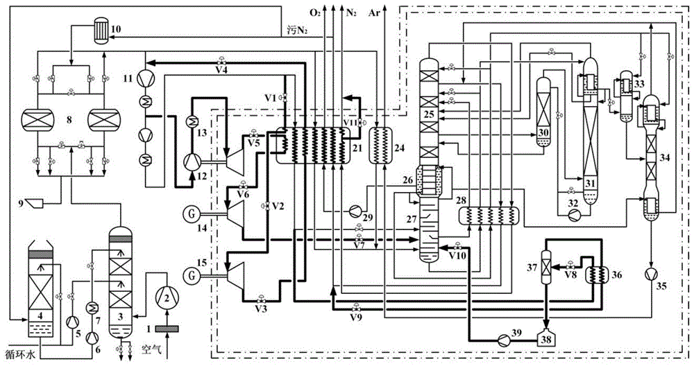
图1为常规内压缩空分工艺流程示意图;Fig. 1 is a schematic diagram of a conventional internal compression air separation process flow;
图2为本发明实施例中制氧40000Nm3·h-1更换中压主换热器一的内压缩空分储能装置储能过程循环制冷空气增压机前回收工艺流程示意图;2 is a schematic diagram of the recovery process before the circulating refrigeration air supercharger during the energy storage process of the internal compression air separation energy storage device of the medium-pressure
图3为本发明实施例中制氧40000Nm3·h-1新增中压主换热器一的内压缩空分储能装置储能过程循环制冷空气增压机前回收工艺流程示意图;3 is a schematic diagram of the recovery process before the circulating refrigeration air booster during the energy storage process of the internal compression air separation energy storage device of the newly added medium pressure
图4为本发明实施例中制氧40000Nm3·h-1更换中压主换热器二的内压缩空分储能装置储能过程循环制冷空气增压机前回收工艺流程示意图;4 is a schematic diagram of the recovery process before the circulating refrigeration air supercharger during the energy storage process of the internal compression air separation energy storage device for replacing the middle pressure
图5为本发明实施例中制氧40000Nm3·h-1新增中压主换热器二的内压缩空分储能装置储能过程循环制冷空气增压机前回收工艺流程示意图;5 is a schematic diagram of the recovery process before the circulating refrigeration air booster during the energy storage process of the internal compression air separation energy storage device of the newly added medium - pressure main heat exchanger 2 in the embodiment of the present invention;
图6为本发明实施例中制氧40000Nm3·h-1更换中压主换热器三的内压缩空分储能装置储能过程循环制冷空气空压机前回收工艺流程示意图;6 is a schematic diagram of the recovery process flow before the circulating refrigeration air air compressor during the energy storage process of the internal compression air separation energy storage device of the medium pressure
图7为本发明实施例中制氧40000Nm3·h-1新增中压主换热器三的内压缩空分储能装置储能过程循环制冷空气空压机前回收工艺流程示意图;7 is a schematic diagram of a process flow diagram of the recovery process before the circulating refrigerating air air compressor during the energy storage process of the internal compression air separation energy storage device of the newly added medium pressure
图8为本发明实施例中压主换热器一的流体通道分布示意图;8 is a schematic diagram of the distribution of the fluid passages of the first medium-pressure main heat exchanger according to the embodiment of the present invention;
图9为本发明实施例中压主换热器二的流体通道分布示意图;9 is a schematic diagram of the distribution of the fluid passages of the second medium-pressure main heat exchanger according to the embodiment of the present invention;
图10为本发明实施例中压主换热器三的流体通道分布示意图;10 is a schematic diagram of the distribution of the fluid passages of the third medium-pressure main heat exchanger according to the embodiment of the present invention;
图11为本发明实施例中制氧40000Nm3·h-1内压缩空分储能装置释能期间液空回收流率对低压塔内产品纯度和氩馏分中氩浓度的影响;Fig. 11 is the influence of the liquid-air recovery flow rate on the product purity in the low-pressure column and the argon concentration in the argon fraction during the energy release of the compressed air separation energy storage device in the oxygen production of 40000Nm 3 ·h -1 in the embodiment of the present invention;
图12为峰谷电价比对本发明实施案例中制氧40000Nm3·h-1更换中压主换热器一的内压缩空分储能装置储能过程循环制冷空气增压机前回收工艺系统用电成本节约率和成本回收期的影响;Figure 12 shows the peak-to-valley electricity price ratio in the case of the implementation of the present invention for oxygen production 40000Nm 3 ·h -1 to replace the internal compression air separation energy storage device of the medium pressure
图13为本发明实施案例中制氧40000Nm3·h-1更换中压主换热器一的内压缩空分储能装置储能过程循环制冷空气增压机前回收工艺系统取代全国内压缩空分设备前、后的年用电负荷变化情况。Fig. 13 shows the energy storage process of the internal compression air separation energy storage device of the medium pressure
其中:1-空气过滤器;2-空气压缩机;3-空冷塔;4-水冷塔;5-冷却水泵;6-冷冻水泵;7-冷水机组;8-分子筛吸附器;9-消声器;10-电加热器;11-空气增压机;12-增压透平膨胀机;13-增压后冷却器;14-透平膨胀发电机一;15-透平膨胀发电机二;16-透平膨胀发电机三;17-透平膨胀发电机四;18-透平膨胀发电机五;19-透平膨胀发电机六;20-原中压主换热器;21-中压主换热器一;22-中压主换热器二;23-中压主换热器三;24-中压氩换热器;25-低压塔;26-主冷凝蒸发器;27-高压塔;28-过冷器;29-液氧泵;30-粗氩I塔;31-粗氩II塔;32-粗液氩循环泵;33-粗氩液化器;34-精氩塔;35-精氩泵;36-液空过冷器;37-常压气液分离器;38-液空储罐;39-低温泵;V1-控制阀门一;V2-控制阀门二;V3-控制阀门三;V4-控制阀门四;V5-控制阀门五;V6-控制阀门六;V7-控制阀门七;V8-控制阀门八;V9-控制阀门九;V10-控制阀门十;V11-控制阀门十一;V12-控制阀门十二;V13-控制阀门十三;V14-控制阀门十四;V15-控制阀门十五;V16-控制阀门十六;V17-控制阀门十七;V18-控制阀门十八;V19-控制阀门十九;V20-控制阀门二十,V21-控制阀门二十一。Among them: 1- air filter; 2- air compressor; 3- air cooling tower; 4- water cooling tower; 5- cooling water pump; 6- chilled water pump; 7- chiller; 8- molecular sieve adsorber; 9- muffler; 10 -Electric heater; 11-air supercharger; 12-supercharger turbo-expander; 13-supercharged aftercooler; 14-turbo-expansion generator one; 15-turbo-expansion generator two; 16-turbine Flat expansion generator three; 17-turbine expansion generator four; 18-turbine expansion generator five; 19-turbine expansion generator six; 20-original medium pressure main heat exchanger; 21- medium pressure main heat exchange Device one; 22-medium pressure main heat exchanger two; 23-medium pressure main heat exchanger three; 24-medium pressure argon heat exchanger; 25-low pressure column; 26-main condensation evaporator; 27-high pressure column; 28 - subcooler; 29- liquid oxygen pump; 30- crude argon I column; 31- crude argon II column; 32- crude liquid argon circulating pump; 33- crude argon liquefier; 34- refined argon column; 35- refined argon Pump; 36-liquid-air subcooler; 37-atmospheric pressure gas-liquid separator; 38-liquid-air storage tank; 39-low temperature pump; V1-control valve one; V2-control valve two; V3-control valve three; V4 - Control valve four; V5- control valve five; V6- control valve six; V7- control valve seven; V8- control valve eight; V9- control valve nine; V10- control valve ten; V11- control valve eleven; V12- Control valve twelve; V13-control valve thirteen; V14-control valve fourteen; V15-control valve fifteen; V16-control valve sixteen; V17-control valve seventeen; V18-control valve eighteen; V19-control valve Valve nineteen; V20-control valve twenty, V21-control valve twenty-one.
具体实施方式Detailed ways
为使本发明要解决的技术问题、技术方案和优点更加清楚,下面将结合附图及具体实施例进行详细描述。In order to make the technical problems, technical solutions and advantages to be solved by the present invention more clear, the following will be described in detail with reference to the accompanying drawings and specific embodiments.
本发明为解决内压缩空分装置储能期间空气液化率低,循环制冷空气环境释放,释能过程低温液空间接回收等问题,提供一种基于内压缩空分储能装置的物质回收方法,实现内压缩空分设备的规模化储能和物质能量的高效循环利用。The invention provides a material recovery method based on an internal compression air separation energy storage device in order to solve the problems of low air liquefaction rate, environmental release of circulating refrigerated air, and low temperature liquid space recovery during energy release during the energy storage period of the internal compression air separation device. To achieve large-scale energy storage and efficient recycling of material energy in internal compression air separation plants.
该方法通过在常规内压缩空分装置的基础上更换中压主换热器20或在保留常规内压缩空分装置中压主换热器20的基础上增设中压主换热器,实现内压缩空分储能装置储能过程循环制冷空气的增压机前回收和释能过程低温液态空气的直接利用。In this method, the medium pressure
如图2,为本发明实施例中制氧40000Nm3·h-1更换中压主换热器一的内压缩空分储能装置储能过程循环制冷空气增压机前回收工艺流程示意图。从图2中可以看出,该基于内压缩空分储能装置的物质回收方法在图1所示常规内压缩空分工艺流程的基础上将原中压主换热器20更换为中压主换热器一21,同时改变原增压透平膨胀机12膨胀端输入和输出管道的限定方式,并增设透平膨胀发电机一14、透平膨胀发电机二15、液空过冷器36、常压气液分离器37、液空储罐38和低温泵39;结合图8给出的中压主换热器一21的流体通道分布示意图可以看出,中压主换热器一21设置循环空气降温通道、增压膨胀空气降温通道、增压后中压空气通道、循环空气复热通道、纯化后低压空气通道、污氮气复热通道、氧气复热通道和氮气复热通道,同时在氮气复热通道上设置中部和上部两个流体抽出位置;其中,中压主换热器一21的循环空气降温通道输入端与现有的空气增压机11的四级冷却器输出端相连,中压主换热器一21的循环空气降温通道输出端与透平膨胀发电机二15的输入端相连,透平膨胀发电机二15的输出端与中压主换热器一21的循环空气复热通道输入端相连,中压主换热器一21的循环空气复热通道输出端与空气增压机11的一级气缸输入端相连;现有的增压透平膨胀机12的增压后冷却器13的输出端与增压透平膨胀机12的膨胀端输入管道相连,增压透平膨胀机12的膨胀端输出管道与中压主换热器一21的增压膨胀空气降温通道输入端相连,中压主换热器一21的增压膨胀空气降温通道输出端与透平膨胀发电机一14的输入端相连,透平膨胀发电机一14的输出端连接于高压塔27的原料输入端;中压主换热器一21的纯化后低压空气通道输入端与分子筛吸附器8的空气输出端相连,中压主换热器一21的纯化后低压空气通道输出端连接于高压塔27的原料输入端;中压主换热器一21的增压后中压空气通道输入端与空气增压机11的四级冷却器输出端相连,中压主换热器一21的增压后中压空气通道输出端分别连接于高压塔27的原料输入端和液空过冷器36的液态空气输入端;中压主换热器一21的污氮气复热通道输入端与过冷器28的污氮气输出端相连,中压主换热器一21的污氮气复热通道输出端连接于污氮气输出管道;中压主换热器一21的氧气复热通道输入端与液氧泵29的输出端相连,中压主换热器一21的氧气复热通道输出端连接于氧气产品输出管道;中压主换热器一21的氮气复热通道输入端与过冷器28的氮气输出端相连,中压主换热器一21的氮气复热通道中部和上部输出端均连接于氮气产品输出管道;液空过冷器36的液态空气输出端与常压气液分离器37的输入端相连;常压气液分离器37的气体输出端与液空过冷器36的低温空气输入端相连,液空过冷器36的低温空气输出端连接于中压主换热器一21的污氮气复热通道输入管道,常压气液分离器37的液体输出端与低温液空储罐38的输入端相连;液空储罐38的输出端与低温泵39的输入端相连,低温泵39的输出端连接于高压塔27的原料输入端。Figure 2 is a schematic diagram of the recovery process before the circulating refrigeration air supercharger during the energy storage process of the internal compression air separation energy storage device of the medium pressure
中压主换热器一21的循环空气降温通道输入端与现有的空气增压机11的四级冷却器输出端之间设置控制阀门一V1,中压主换热器一21的循环空气降温通道输出端与透平膨胀发电机二15的输入端之间设置控制阀门二V2,透平膨胀发电机二15的输出端与中压主换热器一21的循环空气复热通道输入端之间设置控制阀门三V3,中压主换热器一21的循环空气复热通道输出端与空气增压机11的一级气缸输入端之间设置控制阀门四V4;增压透平膨胀机12的膨胀端输出管道与中压主换热器一21的增压膨胀空气降温通道输入端之间设置控制阀门五V5,中压主换热器一21的增压膨胀空气降温通道输出端与透平膨胀发电机一14的输入端之间设置控制阀门六V6,透平膨胀发电机一14的输出端与高压塔27的原料输入端之间设置控制阀门七V7;液空过冷器36的液态空气输出端与常压气液分离器37的输入端之间设置控制阀门八V8,液空过冷器36的低温空气输出端与中压主换热器一21的污氮气复热通道输入管道之间设置控制阀门九V9,低温泵39的输出端与高压塔27的原料输入端之间设置控制阀门十V10,中压主换热器一21的氮气复热通道中部输出端与氮气产品输出管道之间设置控制阀门十一V11;A control valve V1 is set between the input end of the circulating air cooling channel of the medium pressure main heat exchanger-21 and the output end of the four-stage cooler of the existing air supercharger 11, and the circulating air of the medium pressure main heat exchanger-21 A control valve 2 V2 is set between the output end of the cooling channel and the input end of the second turbo-expansion generator 15 , the output end of the second turbo-expansion generator 15 and the input end of the circulating air reheating channel of the medium pressure main heat exchanger 1 21 Control valve 3 V3 is set between them, and control valve 4 V4 is set between the output end of the circulating air reheating channel of the medium pressure main heat exchanger 1 21 and the input end of the primary cylinder of the air booster 11; the booster turbo expander A control valve V5 is set between the output pipe of the expansion end of 12 and the input end of the pressurized expansion air cooling channel of the medium pressure main heat exchanger one 21, and the output end of the pressurized expansion air cooling channel of the medium pressure main heat exchanger one 21 and A control valve six V6 is set between the input end of the turbo-expansion generator one 14, and a control valve seven V7 is set between the output end of the turbo-expansion generator one 14 and the raw material input end of the high pressure tower 27; the liquid-air subcooler 36 A control valve V8 is set between the output end of the liquid air and the input end of the normal pressure gas-liquid separator 37, the low temperature air output end of the liquid-air subcooler 36 and the dirty nitrogen reheating channel of the medium pressure main heat exchanger-21 A control valve 9 V9 is set between the input pipes, a control valve 10 V10 is set between the output end of the cryopump 39 and the raw material input end of the high pressure tower 27, and the middle output end of the nitrogen reheating channel of the medium pressure main heat exchanger 1 21 is connected to the nitrogen gas. Set the control valve eleven V11 between the product output pipelines;
图3为本发明实施例中制氧40000Nm3·h-1新增中压主换热器一的内压缩空分储能装置储能过程循环制冷空气增压机前回收工艺流程示意图;从图3中可以看出,该基于内压缩空分储能装置的物质回收方法还可在图1所示常规内压缩空分工艺流程的基础上保留原内压缩空分装置的中压主换热器20,并在此基础上增设中压主换热器一21、透平膨胀发电机一14、透平膨胀发电机二15、液空过冷器36、常压气液分离器37、液空储罐38和低温泵39,同时改变原增压透平膨胀机12膨胀端输入和输出管道的限定方式,关闭原中压主换热器20增压膨胀空气通道的输入和输出通道,实现内压缩空分储能装置储能过程循环制冷空气的增压机前回收和释能过程低温液态空气的直接利用;3 is a schematic diagram of the recovery process flow before the circulating refrigeration air booster during the energy storage process of the internal compression air separation energy storage device of the newly added medium-pressure
所述原增压透平膨胀机12的增压端输入管道连接于空气增压机11的三级冷却器输出端,增压透平膨胀机12的增压端输出管道连接于增压后冷却器13的输入端;增压透平膨胀机12的膨胀端输入管道连接于增压后冷却器13的输出端,增压透平膨胀机12的膨胀端输出管道连接于中压主换热器一21的增压膨胀空气降温通道输入端;中压主换热器一21的增压膨胀空气降温通道输出端连接于透平膨胀发电机一14的输入端,透平膨胀发电机一14的输出端连接于高压塔27的原料输入端;原中压主换热器20和中压主换热器一21的增压后中压空气通道输入端连接于空气增压机11的四级冷却器输出端,原中压主换热器20和中压主换热器一21的增压后中压空气通道输出端分为两路:一路连接于高压塔27的原料输入端,另一路连接于液空过冷器36的液态空气输入端;原中压主换热器20和中压主换热器一21的纯化后低压空气通道输入端连接于分子筛吸附器8的空气输出端,原中压主换热器20和中压主换热器一21的纯化后低压空气通道输出端连接于高压塔27的原料输入端;原中压主换热器20和中压主换热器一21的氧气复热通道输入端连接于液氧泵29的输出端,原中压主换热器20和中压主换热器一21的氧气复热通道输出端连接于氧气产品输出管道;原中压主换热器20和中压主换热器一21的氮气复热通道输入端连接于过冷器28的氮气输出端,原中压主换热器20和中压主换热器一21的氮气复热通道输出端均连接于氮气产品输出管道;原中压主换热器20和中压主换热器一21的污氮气复热通道输入端连接于过冷器28的污氮气输出端,原中压主换热器20和中压主换热器一21的污氮气复热通道输出端连接于污氮气输出管道;中压主换热器一21的循环空气降温通道输入端连接于空气增压机11的四级冷却器输出端,中压主换热器一21的循环空气降温通道输出端连接于透平膨胀发电机二15的输入端,透平膨胀发电机二15的输出端连接于中压主换热器一21的循环空气复热通道输入端,中压主换热器一21的循环空气复热通道输出端连接于空气增压机11的一级气缸输入端;液空过冷器36、常压气液分离器37、液空储罐38和低温泵39的管道限定方式以及阀门设置均与图2所示更换中压主换热器一21的内压缩空分储能装置储能过程循环制冷空气增压机前回收工艺流程中相应设备和阀门的限定方式相同;The input pipe of the supercharging end of the original
图4为本发明实施例中制氧40000Nm3·h-1更换中压主换热器二的内压缩空分储能装置储能过程循环制冷空气增压机前回收工艺流程示意图;从图4中可以看出,该基于内压缩空分储能装置的物质回收方法也可在图1所示常规内压缩空分工艺流程的基础上将原中压主换热器20更换为中压主换热器二22,并增设透平膨胀发电机三16、透平膨胀发电机四17、液空过冷器36、常压气液分离器37、液空储罐38和低温泵39,实现内压缩空分储能装置储能过程循环制冷空气的增压机前回收和释能过程低温液态空气的直接利用;结合图9给出的中压主换热器二22的流体通道分布示意图可以看出,中压主换热器二22设置循环空气降温通道、增压膨胀空气降温通道、增压后中压空气通道、循环空气复热通道、纯化后低压空气通道、污氮气复热通道、氧气复热通道和氮气复热通道,同时在氮气复热通道上设置中部和上部两个流体抽出位置;透平膨胀发电机三16的输入端与现有的空气增压机11的四级冷却器输出端相连,透平膨胀发电机三16的输出端与中压主换热器二22的循环空气降温通道输入端相连,中压主换热器二22的循环空气降温通道输出端与透平膨胀发电机四17的输入端相连,透平膨胀发电机四17的输出端与中压主换热器二22的循环空气复热通道输入端相连,中压主换热器二22的循环空气复热通道输出端连接于空气增压机11的一级气缸输入端;中压主换热器二22的增压膨胀空气降温通道输入端与现有的增压后冷却器13的输出端相连,中压主换热器二22的增压膨胀空气降温通道输出端与现有的增压透平膨胀机12的膨胀端输入管道相连;中压主换热器二22的纯化后低压空气通道输入端与分子筛吸附器8的空气输出端相连,中压主换热器二22的纯化后低压空气通道输出端与高压塔27的原料输入端相连;中压主换热器二22的增压后中压空气通道输入端与空气增压机11的四级冷却器输出端相连,中压主换热器二22的增压后中压空气通道输出端分别连接于高压塔27的原料输入端和液空过冷器36的液态空气输入端;中压主换热器二22的污氮气复热通道输入端与过冷器28的污氮气输出端相连,中压主换热器二22的污氮气复热通道输出端连接于污氮气输出管道;中压主换热器二22的氧气复热通道输入端与液氧泵29的输出端相连,中压主换热器二22的氧气复热通道输出端连接于氧气产品输出管道;中压主换热器二22的氮气复热通道输入端与过冷器28的氮气输出端相连,中压主换热器二22的氮气复热通道中部和上部输出端均连接于氮气产品输出管道;液空过冷器36的液态空气输出端与常压气液分离器37的输入端相连;常压气液分离器37的气体输出端与液空过冷器36的低温空气输入端相连,液空过冷器36的低温空气输出端连接于中压主换热器二22的污氮气复热通道输入管道,常压气液分离器37的液体输出端与低温液空储罐38的输入端相连;低温泵39的输入端与液空储罐38的输出端相连,低温泵39的输出端连接于高压塔27的原料输入端;Fig. 4 is the schematic diagram of the recovery process flow before the circulating refrigeration air booster during the energy storage process of the internal compression air separation energy storage device of the medium-pressure
透平膨胀发电机三16的输入端与现有的空气增压机11的四级冷却器输出端之间设置控制阀门十二V12,透平膨胀发电机三16的输出端与中压主换热器二22的循环空气降温通道输入端之间设置控制阀门十三V13,中压主换热器二22的循环空气降温通道输出端与透平膨胀发电机四17的输入端之间设置控制阀门十四V14,透平膨胀发电机四17的输出端与中压主换热器二22的循环空气复热通道输入端之间设置控制阀门十五V15,中压主换热器二22的循环空气复热通道输出端与空气增压机11的一级气缸输入端之间设置控制阀门四V4;液空过冷器36的液态空气输出端与常压气液分离器37的输入端之间设置控制阀门八V8,液空过冷器36的低温空气输出端与中压主换热器二22的污氮气复热通道输入管道之间设置控制阀门九V9,低温泵39的输出端与高压塔27的原料输入端之间设置控制阀门十V10,中压主换热器二22的氮气复热通道中部输出端与氮气产品输出管道之间设置控制阀门十一V11;A
图5为本发明实施例中制氧40000Nm3·h-1新增中压主换热器二的内压缩空分储能装置储能过程循环制冷空气增压机前回收工艺流程示意图;从图5中可以看出,该基于内压缩空分储能装置的物质回收方法还可在图1所示常规内压缩空分工艺流程的基础上保留原内压缩空分装置的中压主换热器20,并在此基础上增设中压主换热器二22、透平膨胀发电机三16、透平膨胀发电机四17、液空过冷器36、常压气液分离器37、液空储罐38和低温泵39,实现内压缩空分储能装置储能过程循环制冷空气的增压机前回收和释能过程低温液态空气的直接利用;5 is a schematic diagram of the recovery process flow before the circulating refrigeration air booster during the energy storage process of the internal compression air separation energy storage device of the newly added medium-pressure
原中压主换热器20与中压主换热器二22的增压膨胀空气降温通道输入端连接于增压后冷却器13的输出端,原中压主换热器20与中压主换热器二22的增压膨胀空气降温通道输出端连接于增压透平膨胀机12的膨胀端输入管道;原中压主换热器20与中压主换热器二22的增压后中压空气通道输入端连接于空气增压机11的四级冷却器输出端,原中压主换热器20与中压主换热器二22的增压后中压空气通道输出端分为两路:一路连接于高压塔27的原料输入端,另一路连接于液空过冷器36的液态空气输入端;原中压主换热器20和中压主换热器二22的纯化后低压空气通道输入端连接于分子筛吸附器8的空气输出端,原中压主换热器20和中压主换热器二22的纯化后低压空气通道输出端连接于高压塔27的原料输入端;原中压主换热器20和中压主换热器二22的氧气复热通道输入端连接于液氧泵的输出端,中压主换热器和中压主换热器二的氧气复热通道输出端连接于氧气产品输出管道;原中压主换热器20和中压主换热器二22的氮气复热通道输入端连接于过冷器28的氮气输出端,原中压主换热器20和中压主换热器二22的氮气复热通道输出端均连接于氮气产品输出管道;原中压主换热器20和中压主换热器二22的污氮气复热通道输入端连接于过冷器28的污氮气输出端,原中压主换热器20和中压主换热器二22的污氮气复热通道输出端连接于污氮气输出管道;透平膨胀发电机三16的输入端连接于空气增压机11的四级冷却器输出端,透平膨胀发电机三16的输出端连接于中压主换热器二22的循环空气降温通道输入端,中压主换热器二22的循环空气降温通道输出端连接于透平膨胀发电机四17的输入端,透平膨胀发电机四17的输出端连接于中压主换热器二22的循环空气复热通道输入端,中压主换热器二22的循环空气复热通道输出端连接于空气增压机11的一级气缸输入端;液空过冷器26、常压气液分离器37、液空储罐38和低温泵39的管道限定方式以及阀门设置均与图4所示更换中压主换热器二22的内压缩空分储能装置储能过程循环制冷空气增压机前回收工艺流程中相应设备和阀门的限定方式相同;The input ends of the pressurized expansion air cooling channels of the original medium pressure
图6为本发明实施例中制氧40000Nm3·h-1更换中压主换热器三的内压缩空分储能装置储能过程循环制冷空气空压机前回收工艺流程示意图;从图6中可以看出,该基于内压缩空分储能装置的物质回收方法也可在图1所示常规内压缩空分工艺流程的基础上将原中压主换热器20更换为中压主换热器三23,并增设透平膨胀发电机三16、透平膨胀发电机五18、透平膨胀发电机六19、液空过冷器36、常压气液分离器37、液空储罐38和低温泵39,实现内压缩空分储能装置储能过程循环制冷空气的空压机前回收和释能过程低温液态空气的直接利用;结合图10给出的中压主换热器三23的流体通道分布示意图可以看出,中压主换热器三23设置增压膨胀空气降温通道、循环空气一次复热通道、循环空气二次复热通道、循环空气三次复热通道、增压后中压空气通道、纯化后低压空气通道、污氮气复热通道、氧气复热通道和氮气复热通道,同时氮气复热通道上设置中部和上部两个流体抽出位置;透平膨胀发电机三16的输入端与现有的空气增压机11的四级冷却器输出端相连,透平膨胀发电机三16的输出端与中压主换热器三23的循环空气一次复热通道输入端相连,中压主换热器三23的循环空气一次复热通道输出端与透平膨胀发电机五18的输入端相连,透平膨胀发电机五18的输出端与中压主换热器三23的循环空气二次复热通道输入端相连,中压主换热器三23的循环空气二次复热通道输出端与透平膨胀发电机六19的输入端相连,透平膨胀发电机六19的输出端与中压主换热器三23的循环空气三次复热通道输入端相连,中压主换热器三23的循环空气三次复热通道输出端与现有的空气压缩机2的原料气输入端相连;中压主换热器三23的增压膨胀空气降温通道输入端与现有的增压后冷却器13的输出端相连,中压主换热器三23的增压膨胀空气降温通道输出端与现有的增压透平膨胀机12的膨胀端输入管道相连;中压主换热器三23的纯化后低压空气输入端与分子筛吸附器8的空气输出端相连,中压主换热器三23的纯化后低压空气输出端与高压塔27的原料输入端相连;中压主换热器三23的增压后中压空气输入端与空气增压机11的四级冷却器输出端相连,中压主换热器三23的增压后中压空气输出端分别连接于高压塔27的原料输入端和液空过冷器36的液态空气输入端;中压主换热器三23的污氮气复热通道输入端与过冷器28的污氮气输出端相连,中压主换热器三23的污氮气复热通道输出端连接于污氮气输出管道;中压主换热器三23的氧气复热通道输入端与液氧泵29的输出端相连,中压主换热器三23的氧气复热通道输出端连接于氧气产品输出管道;中压主换热器三23的氮气复热通道输入端与过冷器28的氮气输出端相连,中压主换热器三23的氮气复热通道中部和上部输出端均连接于氮气产品输出管道;液空过冷器36的液态空气输出端与常压气液分离器37的输入端相连;常压气液分离器37的气体输出端与液空过冷器36的低温空气输入端相连,液空过冷器36的低温空气输出端与中压主换热器三23的污氮气复热通道输入管道相连,常压气液分离器37的液体输出端与低温液空储罐38的输入端相连;低温泵39的输入端与液空储罐38的输出端相连,低温泵39的输出端与高压塔27的原料输入端相连;6 is a schematic diagram of the recovery process flow before the circulating refrigeration air air compressor during the energy storage process of the internal compression air separation energy storage device of the medium-pressure
透平膨胀发电机三16的输入端与现有的空气增压机11的四级冷却器输出端之间设置控制阀门十二V12,透平膨胀发电机三16的输出端与中压主换热器三23的循环空气一次复热通道输入端之间设置控制阀门十六V16,中压主换热器三23的循环空气一次复热通道输出端与透平膨胀发电机五18的输入端之间设置控制阀门十七V17,透平膨胀发电机五18的输出端与中压主换热器三23的循环空气二次复热通道输入端之间设置控制阀门十八V18,中压主换热器三23的循环空气二次复热通道输出端与透平膨胀发电机六19的输入端之间设置控制阀门十九V19,透平膨胀发电机六19的输出端与中压主换热器三23的循环空气三次复热通道输入端之间设置控制阀门二十V20,中压主换热器三23的循环空气三次复热通道输出端与现有空气压缩机2的原料气输入端之间设置控制阀门二十一V21;液空过冷器36的液态空气输出端与常压气液分离器37的输入端之间设置控制阀门八V8,液空过冷器36的低温空气输出端与中压主换热器三23的污氮气复热通道输入管道之间设置控制阀门九V9,低温泵39的输出端与高压塔27的原料输入端之间设置控制阀门十V10,中压主换热器三23的氮气复热通道中部输出端与氮气产品输出管道之间设置控制阀门十一V11;A
图7为本发明实施例中制氧40000Nm3·h-1新增中压主换热器三的内压缩空分储能装置储能过程循环制冷空气空压机前回收工艺流程示意图;从图7中可以看出,该基于内压缩空分储能装置的物质回收方法还可在图1所示常规内压缩空分工艺流程的基础上保留原内压缩空分装置的中压主换热器20,并增设中压主换热器三23、透平膨胀发电机三16、透平膨胀发电机五18、透平膨胀发电机六19、液空过冷器36、常压气液分离器37、液空储罐38和低温泵39,实现内压缩空分储能装置储能过程循环制冷空气的空压机前回收和释能过程低温液态空气的直接利用;FIG. 7 is a schematic diagram of the recovery process flow before the circulating refrigeration air air compressor during the energy storage process of the internal compression air separation energy storage device of the newly added medium pressure
透平膨胀发电机三16的输入端连接于空气增压机11的四级冷却器输出端,透平膨胀发电机三16的输出端连接于中压主换热器三23的循环空气一次复热通道输入端,中压主换热器三23的循环空气一次复热通道输出端连接于透平膨胀发电机五18的输入端,透平膨胀发电机五18的输出端连接于中压主换热器三23的循环空气二次复热通道输入端,中压主换热器三23的循环空气二次复热通道输出端连接于透平膨胀发电机六19的输入端,透平膨胀发电机六19的输出端连接于中压主换热器三23的循环空气三次复热通道输入端,中压主换热器三23的循环空气三次复热通道输出端连接于空气压缩机2的原料气输入端;原中压主换热器20和中压主换热器三23的增压膨胀空气降温通道输入端连接于增压后冷却器13的输出端,原中压主换热器20和中压主换热器三23的增压膨胀空气降温通道输出端连接于增压透平膨胀机12的膨胀端输入管道;原中压主换热器20和中压主换热器三23的纯化后低压空气输入端连接于分子筛吸附器8的空气输出端,原中压主换热器20和中压主换热器三23的纯化后低压空气输出端连接于高压塔27的原料输入端;原中压主换热器20和中压主换热器三23的增压后中压空气输入端连接于空气增压机11的四级冷却器输出端,原中压主换热器20和中压主换热器三23的增压后中压空气输出端分为两路:一路连接于高压塔27的原料输入端,另一路连接于液空过冷器36的液态空气输入端;原中压主换热器20和中压主换热器三23的污氮气复热通道输入端连接于过冷器28的污氮气输出端,原中压主换热器20和中压主换热器三23的污氮气复热通道输出端连接于污氮气输出管道;原中压主换热器20和中压主换热器三23的氧气复热通道输入端连接于液氧泵29的输出端,原中压主换热器20和中压主换热器三23的氧气复热通道输出端连接于氧气产品输出管道;原中压主换热器20和中压主换热器三23的氮气复热通道输入端连接于过冷器28的氮气输出端,原中压主换热器20和中压主换热器三23的氮气复热通道输出端均连接于氮气产品输出管道;液空过冷器36、常压气液分离器37、液空储罐38和低温泵39的管道限定方式和阀门设置均与图6所示更换中压主换热器三23的内压缩空分储能装置储能过程循环制冷空气空压机前回收工艺流程中相应设备和阀门的限定方式相同。The input end of the turbo-
下面结合具体实施例予以说明。The following description will be given in conjunction with specific embodiments.
如图2所示为本发明实施例中制氧40000Nm3·h-1更换中压主换热器一的内压缩空分储能装置储能过程循环制冷空气增压机前回收工艺流程示意图。储能过程,原料空气经空气过滤器1去除灰尘后进入空气压缩机2进行压缩,之后进入空冷塔3进行冷却和洗涤,空冷塔3用于冷却空气的水有两部分:一部分为冷却循环水,由冷却水泵5加压后送入空冷塔3中部;另一部分为冷冻水,由来自精馏系统的干燥污氮气和氮气在水冷塔4内对循环冷却水进行初步降温,之后经冷冻水泵6加压,并由冷水机组7进一步降温后送入空冷塔3顶部。出空冷塔3的空气进入分子筛吸附器8进行吸附和纯化,获得纯净干燥的空气。分子筛吸附器8有两台,交替使用,一台吸附杂质,另一台由污氮气在电加热器10内加热后对其进行再生,分子筛吸附器8处设置消声器9。Figure 2 is a schematic diagram of the recovery process before the circulating refrigeration air booster during the energy storage process of the internal compression air separation energy storage device of the medium pressure
来自分子筛吸附器8的纯化后干燥空气分为两路:一路进入中压氩换热器24和中压主换热器一21被冷却至露点温度后进入高压塔27;另一路为再增压空气,经空气增压机11一、二、三级压缩和冷却后分两部分:一部分作为增压膨胀空气从级间抽出,另一部分在空气增压机11内进行四级压缩和冷却;其中,级间抽出的增压膨胀空气首先进入增压透平膨胀机12的增压端,经增压后冷却器13降温后再通过增压透平膨胀机12的膨胀端,膨胀后的空气进入中压主换热器一21的增压膨胀空气降温通道,被返流气体冷却到一定温度后出中压主换热器一21,之后进入透平膨胀发电机一14,经透平膨胀发电机一14膨胀后的空气进入高压塔27的底部参与精馏;在空气增压机11内进行四级压缩和冷却后的中压空气分为两部分:一部分作为循环制冷空气,进入中压主换热器一21,冷却到一定温度后从中压主换热器一21的中上部抽出,之后进入透平膨胀发电机二15,经透平膨胀发电机二15膨胀到接近空气压缩机2的输出压力时,以返流气体形式进入中压主换热器一21进行复热,复热后的空气再次进入空气增压机11;另一部分作为空气液化原料,经中压主换热器一21内的返流低温介质冷却为过冷液体后分为两部分:一部分直接节流进入高压塔27;另一部分经液空过冷器36,被来自常压气液分离器37分离所得的低温空气再次降温后节流至常压,并进入常压气液分离器37进行分离。常压气液分离器37分离所得的液体即为所要储存的液空产品,进入低温液空储罐38,分离所得的气体经液空过冷器36回收部分冷能后,以返流气体形式并入中压主换热器一21的污氮气复热管道。The purified dry air from the
进入高压塔27的原料在塔内因相对挥发度不同而进行组分分离,高压塔27底部得到含氧约37%的富氧液空,高压塔27顶部得到高纯度氮气,高纯度氮气经过主冷凝蒸发器26与来自低压塔25底部的液氧进行热交换,液氧被蒸发,氮气被冷凝,部分冷凝液氮再回到高压塔27作为回流液,另一部分液氮在过冷器28中进行过冷,并分为两路:一路送入低压塔25顶部作为回流液,另一路分别送入粗氩液化器33和精氩塔34顶部用来冷凝气氩。高压塔27侧面采出的部分液空经过冷器28冷却为过冷液体后节流进入低压塔25中部参与精馏,来自高压塔27底部的液空同样经过冷器28被冷却为过冷液体,之后分为两部分:一部分节流到低压塔25中部参与精馏,另一部分送入粗氩II塔31顶部。在低压塔25内,由于氧、氩、氮沸点的差异,经多次部分冷凝和蒸发,低压塔25底部得到纯度为99.6%以上的液氧,该液氧经液氧泵29加压,之后进入中压主换热器一21,经气化和复热后出冷箱作为氧产品送出。低压塔25的中上部抽出污氮气,经过冷器28和中压主换热器一21复热后分为两部分:一部分去纯化系统作再生气,另一部分送入预冷系统的水冷塔4。低压塔25的顶部抽出纯度高于99.99%的氮气,经过冷器28回收部分冷量后进入中压主换热器一21内进行复热,之后以中抽和顶抽形式作为氮气产品抽出。低压塔25中部抽出的富含氩馏分气体直接进入粗氩I塔30的底部,与来自粗氩II塔31底部经粗液氩循环泵32加压后的粗氩在塔内进行对流接触换热和逐级分离,粗氩I塔30底部可得纯度较高的液氧,并将其返送回低压塔25中部,粗氩I塔30顶部所得气体为粗气氩,直接送入粗氩II塔31底部,该气体上升到塔顶时被过冷后的液空所冷凝,并为塔内精馏提供回流液,吸热后的液空重返低压塔25参与精馏,最终由塔顶得到富含氮组分的粗氩气,并进入粗氩液化器33,由底部得到较纯液氩,然后进入精氩塔34进行氮氩组分分离,由塔底部得到纯液氩,所得纯液氩由精氩泵35加压后进入中压氩换热器24,复热后送入氩气管网。The raw materials entering the high-
释能过程在峰电或平电期间进行,该过程中,增压透平膨胀机12、透平膨胀发电机一14、透平膨胀发电机二15、液空过冷器36和常压气液分离器37停止运行,控制阀门一V1、控制阀门二V2、控制阀门三V3、控制阀门四V4、控制阀门五V5、控制阀门六V6、控制阀门七V7、控制阀门八V8(节流阀)、和控制阀门九V9均处于关闭状态。控制阀门十V10和控制阀门十一V11打开,液空储罐38内的液化空气由液空泵39加压到一定压力后全部送入高压塔27参与精馏,此时,空气压缩机2的进气量相应减小,空气增压机11的输出压力相应降低,该过程中其余设备的运行方式均与储能过程相同。The energy release process is carried out during peak power or flat power. During this process, the turbo-
图4为本发明实施例中制氧40000Nm3·h-1更换中压主换热器二的内压缩空分储能装置储能过程循环制冷空气增压机前回收工艺流程示意图;从图中可以看出,该基于空分储能装置的物质回收方法与更换中压主换热器一的内压缩空分储能装置储能过程循环制冷空气增压机前回收工艺流程的主要区别在于储能期间的膨胀制冷过程。储能过程中,来自分子筛吸附器8的纯化后干燥空气分为两路:一路进入中压氩换热器24和中压主换热器二22被冷却至露点温度后进入高压塔27;另一路为再增压空气,经空气增压机11一、二、三级压缩和冷却后分两部分:一部分作为增压膨胀空气从级间抽出,另一部分在空气增压机11内进行四级压缩和冷却;其中,级间抽出的增压膨胀空气首先进入增压透平膨胀机12的增压端,经增压后冷却器13冷却后进入中压主换热器二22的增压膨胀空气通道被返流气体冷却,之后从中压主换热器二22的中部抽出,进入增压透平膨胀机12的膨胀端,膨胀至接近高压塔27压力后直接进入高压塔27底部参与精馏;经空气增压机11四级压缩和冷却后的中压空气分为两路:一路作为循环制冷空气,经透平膨胀发电机三16膨胀后进入中压主换热器二22,被返流介质冷却到一定温度后出中压主换热器二22,同时进入透平膨胀发电机四17,经透平膨胀发电机四17膨胀到接近空气压缩机2的空气输出压力时,以返流气体形式进入中压主换热器二22进行复热,复热后的空气再次进入空气增压机11;另一路作为空气液化原料,经中压主换热器二22内的返流低温介质冷却为过冷液体后分为两部分:一部分直接节流进入高压塔27;另一部分经液空过冷器36,被来自常压气液分离器37分离所得的低温空气再次降温后节流至常压,并进入常压气液分离器37进行分离。常压气液分离器37分离所得的液体即为所要储存的液空产品,进入低温液空储罐38,分离所得的气体经液空过冷器36回收部分冷能后,以返流气体形式并入中压主换热器二22的污氮气复热管道。4 is a schematic diagram of the recovery process flow before the circulating refrigeration air supercharger during the energy storage process of the internal compression air separation energy storage device of the medium-pressure
图6为本发明实施例中制氧40000Nm3·h-1更换中压主换热器三的内压缩空分储能装置储能过程循环制冷空气空压机前回收工艺流程示意图;从图中可以看出,该基于空分储能装置的物质回收方法与更换中压主换热器一的内压缩空分储能装置储能过程循环制冷空气增压机前回收工艺流程的主要区别在于储能期间的膨胀制冷过程。储能过程中,来自分子筛吸附器8的纯化后干燥空气分为两路:一路进入中压氩换热器24和中压主换热器三23被冷却至露点温度后进入高压塔27;另一路为再增压空气,经空气增压机11一、二、三级压缩和冷却后分两部分:一部分作为增压膨胀空气从级间抽出,另一部分在空气增压机11内进行四级压缩和冷却;其中,级间抽出的增压膨胀空气首先进入增压透平膨胀机12的增压端,经增压后冷却器13冷却后进入中压主换热器三23的增压膨胀空气通道被返流气体冷却,之后从中压主换热器三23的中部抽出,进入增压透平膨胀机12的膨胀端,膨胀至接近高压塔27压力后直接进入高压塔27底部参与精馏;经空气增压机11四级压缩和冷却后的中压空气分为两路:一路作为循环制冷空气,经透平膨胀发电机三16膨胀后以返流气体形式进入中压主换热器三23进行复热,一次复热后的循环空气依次通过透平膨胀发电机五18和中压主换热器三23进行二次膨胀和二次复热,之后再通过透平膨胀发电机六19和中压主换热器三23进行三次膨胀和三次复热,最终回收进入空气压缩机2;另一路作为空气液化原料,经中压主换热器三23内的返流低温介质冷却为过冷液体后分为两部分:一部分直接节流进入高压塔27;另一部分经液空过冷器36,被来自常压气液分离器37分离所得的低温空气再次降温后节流至常压,并进入常压气液分离器37进行分离。常压气液分离器37分离所得的液体即为所要储存的液空产品,进入低温液空储罐38,分离所得的气体经液空过冷器36回收部分冷能后,以返流气体形式并入中压主换热器三23的污氮气复热管道。6 is a schematic diagram of the recovery process before the circulating refrigeration air air compressor during the energy storage process of the internal compression air separation energy storage device of the medium-pressure
本过程以上述制氧40000Nm3·h-1更换中压主换热器一的内压缩空分储能装置储能过程循环制冷空气增压机前回收方法为例。考虑到常规空分装置的负荷调节范围为产品设计负荷的70-105%,而目前冶金空分设备的平均运行负荷基本维持在产品设计负荷的80%。假设电网峰、平、谷电时长均为8h,电价以表1所示中国上海市工业电价为标准,通过对该工艺流程实施电力需求侧管理,设计选择谷电储能期间空分设备的压缩负荷为产品设计负荷的105%,精馏系统的运行负荷为产品设计负荷的80%;峰电和平电期间,储存的低温液空直接回收进入高压塔,空压机运行负荷相应减小(不低于产品设计负荷的70%),精馏系统继续维持在80%设计负荷下运行。This process takes the above-mentioned recovery method before the circulating refrigeration air booster during the energy storage process of the internal compression air separation energy storage device of the medium pressure
表1.上海市工业电价标准Table 1. Shanghai Industrial Electricity Price Standard

本发明通过利用ASPEN PLUS V10模拟软件对上述实例的储、释能过程进行建模和初步模拟计算,并将其与全天运行负荷为80%的常规内压缩空分装置运行情况进行对比。模拟过程中,假设液空储罐内液体日损失率为0.2%,压缩机和空气增压机的机械效率为0.98、多变效率为0.87,膨胀机的等熵效率和机械效率分别为0.88和0.97,低温泵的机械效率为0.75,各管路和设备组件中的能量和阻力损失均忽略不计。模拟结果表明,储能过程将循环制冷空气回收进入空气增压机可显著提高空分储能装置的制冷能力,使空分富余产能的空气最大限度液化,即谷电期间液空储存流率可达51958kg/h,总储液量为416t,释能过程对这些低温液空进行回收,回收期可持续16h(峰电+平电),即每小时的液空回收量为25927kg,空压机压缩负荷可下调到70%。The present invention uses ASPEN PLUS V10 simulation software to model and calculate the energy storage and release process of the above example, and compare it with the operation of a conventional internal compression air separation plant with an all-day operating load of 80%. In the simulation process, it is assumed that the daily loss rate of liquid in the air-liquid storage tank is 0.2%, the mechanical efficiency of the compressor and the air booster is 0.98, the variable efficiency is 0.87, and the isentropic efficiency and mechanical efficiency of the expander are 0.88 and 0.88, respectively. 0.97, the mechanical efficiency of the cryopump is 0.75, and the energy and resistance losses in each pipeline and equipment components are negligible. The simulation results show that recycling the circulating cooling air into the air booster during the energy storage process can significantly improve the cooling capacity of the air separation energy storage device and maximize the liquefaction of the air with excess air separation capacity. It reaches 51958kg/h, and the total liquid storage capacity is 416t. The energy release process recycles these low-temperature liquid air, and the recovery period can last for 16h (peak power + flat power), that is, the liquid air recovery per hour is 25927kg, and the air compressor The compressive load can be adjusted down to 70%.
本技术领域人员所熟知的是,对于常规空分而言,通常要求低压塔内输出的氮和氧产品纯度分别不低于99.99和99.6mol%,富氩馏分中的氩浓度不低于8mol%。而对于该实施案例的储能过程,其液空储存系统与空分精馏系统相互独立,产品纯度不受影响。但在液空回收过程中,由于储能期间产生的低温液态空气中的氧浓度高于环境空气中的氧纯度,故释能过程回收这部分液态空气后会导致精馏系统原料中的氧浓度有所升高,从而影响最终的氧、氮产品纯度和氩馏分中的氩浓度。图11为释能期间液空回收流率对低压塔内产品纯度和氩馏分中氩浓度的影响曲线图。可以看出,液空回收进入高压塔前,低压塔内的氮气和液氧产品纯度分别为99.99和99.89mol%,氩馏分中的氩浓度为8.94mol%,均满足空分产品生产需求。在维持精馏塔内回流比不变的情况下,随着释能液空流率的增大,低压塔内的氮产品纯度和氩馏分中的氩浓度逐渐降低,氧产品纯度逐渐增大。当液空进入高压塔的流率达到7.2kg/s(25927kg/h)时,低压塔内的氧产品纯度和氩馏分中的氩浓度分别为99.90和8.60mol%,而氮产品纯度降低到99.9898mol%,低于常规空分产品纯度要求。适当增大高压塔内回流比可有效提高高压塔塔顶氮气纯度,使得低压塔内回流液氮中的氮浓度增加,进而提高低压塔塔顶氮产品纯度。当高压塔内回流比增大1%时,低压塔顶部氮组分浓度升高到99.993%,此时,液氧浓度和富氩馏分中的氩浓度也满足生产浓度要求,说明该技术的实施案例具有可行性。It is well known to those skilled in the art that, for conventional air separation, it is usually required that the purity of nitrogen and oxygen products output from the low-pressure column should not be lower than 99.99 and 99.6 mol%, respectively, and the argon concentration in the argon-rich fraction should not be lower than 8 mol%. . For the energy storage process of this implementation case, the air liquid storage system and the air separation rectification system are independent of each other, and the product purity is not affected. However, in the liquid air recovery process, since the oxygen concentration in the low-temperature liquid air generated during the energy storage period is higher than the oxygen purity in the ambient air, the recovery of this part of the liquid air in the energy release process will lead to the oxygen concentration in the raw material of the rectification system. increased, affecting the final oxygen and nitrogen product purity and argon concentration in the argon fraction. Figure 11 is a graph showing the effect of the liquid air recovery flow rate on the product purity in the low pressure column and the argon concentration in the argon fraction during energy release. It can be seen that before the liquid air is recovered into the high-pressure tower, the nitrogen and liquid oxygen product purities in the low-pressure tower are 99.99 and 99.89 mol% respectively, and the argon concentration in the argon fraction is 8.94 mol%, both of which meet the production requirements of air separation products. Under the condition that the reflux ratio in the rectification column is maintained unchanged, with the increase of the air flow rate of the energy releasing liquid, the nitrogen product purity in the low pressure column and the argon concentration in the argon fraction gradually decrease, and the oxygen product purity gradually increases. When the flow rate of air liquid entering the high pressure column reaches 7.2kg/s (25927kg/h), the oxygen product purity in the low pressure column and the argon concentration in the argon fraction are 99.90 and 8.60mol%, respectively, while the nitrogen product purity is reduced to 99.9898 mol%, lower than the purity requirements of conventional air separation products. Properly increasing the reflux ratio in the high-pressure column can effectively improve the nitrogen purity at the top of the high-pressure column, so that the nitrogen concentration in the reflux liquid nitrogen in the low-pressure column increases, thereby improving the purity of the nitrogen product at the top of the low-pressure column. When the reflux ratio in the high-pressure column increases by 1%, the nitrogen component concentration at the top of the low-pressure column increases to 99.993%. At this time, the liquid oxygen concentration and the argon concentration in the argon-rich fraction also meet the production concentration requirements, indicating the implementation of this technology. The case is feasible.
本发明基于该装置储释能过程的综合耗电情况,系统地分析了其电-电转换效率和经济效益,评估了其实施对中国电网用电负荷的影响和节能减排效益。计算结果表明,以80%负荷运行的40000Nm3/h常规内压缩空分装置的耗电功率为26751KW(包括分子筛再生电耗和氮气压缩电耗),储能期间,随着循环制冷空气量的增大,液空储存流率增加,耗电量也不断增大,当液空储存流率达到51958kg/h时,进入空气增压机的循环制冷空气量趋于稳定,耗电功率为48849KW,相比80%负荷运行的常规内压缩空分装置,其耗电功率增加82.61%;释能期间,液空直接回收进入高压塔的流率为25927kg/h,释能周期为16h,空气压缩机的运行负荷相应减小,装置总耗电功率可降低到18110KW,相比80%负荷运行的常规内压缩空分装置,其耗电功率减小32.30%,考虑到装置的释能周期为储能时长的两倍,故装置综合电-电转换效率可达78.2%。Based on the comprehensive power consumption of the energy storage and release process of the device, the present invention systematically analyzes its electricity-to-electricity conversion efficiency and economic benefits, and evaluates the impact of its implementation on the electricity load of China's power grid and the benefits of energy conservation and emission reduction. The calculation results show that the power consumption of a 40000Nm 3 /h conventional internal compression air separation unit operating at 80% load is 26751KW (including the power consumption of molecular sieve regeneration and nitrogen compression). Increase, the liquid-air storage flow rate increases, and the power consumption also continues to increase. When the liquid-air storage flow rate reaches 51958kg/h, the circulating refrigeration air volume entering the air booster tends to be stable, and the power consumption is 48849KW. Compared with the conventional internal compression air separation unit operating at 80% load, its power consumption increases by 82.61%; during the energy release period, the flow rate of liquid air directly recovered into the high-pressure tower is 25927kg/h, the energy release period is 16h, and the air compressor The operating load of the air separation unit is correspondingly reduced, and the total power consumption of the device can be reduced to 18110KW. Compared with the conventional internal compression air separation unit operating at 80% load, its power consumption is reduced by 32.30%. Considering that the energy release period of the device is energy storage The time is twice as long, so the comprehensive electricity-to-electricity conversion efficiency of the device can reach 78.2%.
图12为峰谷电价比对本发明实施案例中制氧40000Nm3·h-1更换中压主换热器一的内压缩空分储能装置储能过程循环制冷空气增压机前回收工艺系统用电成本节约率和成本回收期的影响。可以看出,峰谷电价比越大,空分储能装置相对常规内压缩空分装置的用电成本节约率越高,新增储能设备的投资成本回收期越小。当峰谷电价比为3:1时,相比80%负荷运行的常规内压缩空分装置,该储能装置的用电成本节约率为12.76%,新增储能相关设备的成本回收期为2.3年;若以上海市工业电价计,其相比80%负荷运行的常规内压缩空分装置的用电成本节约率可达14.39%,新增储能相关设备的成本回收期为1.9年。随着电力市场峰谷电价实施力度的加大,本实施案例的经济效益将更加显著。Figure 12 shows the peak-to-valley electricity price ratio in the case of the implementation of the present invention for oxygen production 40000Nm 3 ·h -1 to replace the internal compression air separation energy storage device of the medium pressure
另外,考虑到空分设备在工业领域的应用范围和耗电占比,该内压缩空分储能装置和物质回收方法将会显著改善我国的电网峰谷用电需求,对于促进电网削峰填谷,以及推动小型发电机组向基负荷机组或大型发电机组转变具有重要意义。2020年,中国粗钢产量为10.65亿吨,按每吨钢平均耗氧量120Nm3,单位氧气综合电耗为0.77KWh/Nm3计,全国冶金空分生产年耗电量可达984.06亿KWh,因冶金空分制氧能力占全国总制氧能力的25%,按内、压外压缩空分设备各占50%计,则2020年全国内压缩空分设备生产耗电总量为1968.12亿KWh,分摊到峰、平、谷三个时段,全国内压缩空分设备的峰、平、谷用电量分别为656.04亿KWh。如图13所示,若全国常规内压缩空分设备均由该基于内压缩空分储能装置储能过程循环制冷空气增压机前回收工艺系统所取代,并对其实施电力需求侧管理,使其全面参与电网调峰,则中国电网的年谷电负荷需求将上升542亿kWh,平电和峰电年负荷需求将均下降212和212亿kWh,全行业应用后降低电网峰谷差率约9.4%(当前为25.98%),可有效提高电网发电机组的稳定性和运行效率。电网峰谷差的减小还可促使部分小中型调峰机组转为基负荷机组或被新型大容量发电机组所取代,从而降低发电煤耗和污染物排放。基于电网“低负荷”调峰节煤计算模型(见表2)及其不同容量发电机组的煤耗情况(见表3),新工艺流程参与中国电网调峰后,若使部分300MW的中小型常规“低负荷”调峰机组被660MW或1000MW的大型超临界机组取代,其因削峰填谷所产生的年节煤效益可达3.05-9.82Mtce(忽略平电负荷下降所产生的节煤效益),降低碳排放2.73-8.77Mt(或实现CO2减排9.99-32.17Mt)。若利用大型超临界机组来取代200MW及其以下的小型调峰机组,其节能减排效果将更加显著。In addition, considering the application range and power consumption ratio of air separation equipment in the industrial field, the internal compression air separation energy storage device and material recovery method will significantly improve the peak-to-valley electricity demand of my country's power grid. It is of great significance to promote the transformation of small generating units to base load units or large generating units. In 2020, China's crude steel output will be 1.065 billion tons. Based on the average oxygen consumption per ton of steel of 120Nm 3 and the comprehensive power consumption per unit of oxygen of 0.77KWh/Nm 3 , the annual power consumption of national metallurgical air separation production can reach 98.406 billion KWh. , because the oxygen production capacity of metallurgical air separation accounts for 25% of the national total oxygen production capacity, and the internal and external compressed air separation equipment each account for 50%, the total power consumption of the national compressed air separation equipment production in 2020 will be 196.812 billion KWh is allocated to the peak, flat and valley periods. The peak, flat and valley electricity consumption of compressed air separation plants in the country is 65.604 billion KWh respectively. As shown in Figure 13, if the conventional internal compression air separation equipment in the country is replaced by the recycling process system based on the energy storage process of the internal compression air separation energy storage device, and the power demand side management is implemented for it, If it fully participates in power grid peak regulation, the annual valley load demand of China's power grid will increase by 54.2 billion kWh, and the annual load demand of flat and peak power will both decrease by 21.2 billion and 21.2 billion kWh. About 9.4% (currently 25.98%), which can effectively improve the stability and operating efficiency of grid generators. The reduction of the peak-to-valley difference in the power grid can also prompt some small and medium-sized peak-shaving units to be converted into base-load units or replaced by new large-capacity generating units, thereby reducing coal consumption and pollutant emissions for power generation. Based on the power grid "low load" peak regulation and coal saving calculation model (see Table 2) and the coal consumption of power generating units with different capacities (see Table 3), after the new process is involved in peak regulation of China's power grid, if some 300MW small and medium-sized conventional The "low-load" peak-shaving unit is replaced by a 660MW or 1000MW large-scale supercritical unit, and the annual coal-saving benefit due to peak shaving and valley filling can reach 3.05-9.82Mtce (ignoring the coal-saving benefit generated by the reduction of the flat load) , reducing carbon emissions by 2.73-8.77Mt (or achieving CO 2 emission reductions of 9.99-32.17Mt). If large-scale supercritical units are used to replace small peak-shaving units of 200MW and below, the effect of energy saving and emission reduction will be more significant.
表2低负荷调峰模式节煤量计算Table 2 Calculation of coal saving in low load peak regulation mode

表3燃煤发电机组运行基本参数Table 3. Basic parameters of coal-fired generator set operation

本发明将低温液空储能技术集成融入到内压缩空分装置中,实现了单一技术在一种装备上的规模化分布式储能。该装置技术针对储能过程循环制冷空气和释能过程低温液空的回收利用,通过调节循环制冷量和合理匹配中压主换热器内的制冷能级,建立了配套的空分储能装置和工艺流程,实现了空分富余产能空气的最大限度储能。该技术相比常规液化空气储能技术,既减少了设备用量,又节约了后期的设备运营维护和人力资源投资成本,提高谷期用电负荷和节约峰电用量的同时,企业经济效益显著提高。因此,其应用对企业有经济效益,对电网侧有节能减排效益,是企业经济效益和国家经济与环境效益的完美统一。The invention integrates the low-temperature liquid-air energy storage technology into the internal compression air separation device, and realizes the large-scale distributed energy storage of a single technology on one type of equipment. This device technology is aimed at the recycling of circulating refrigeration air in the energy storage process and low-temperature liquid air in the energy release process. By adjusting the circulating refrigeration capacity and reasonably matching the refrigeration energy level in the medium-pressure main heat exchanger, a supporting air separation energy storage device is established. And the process flow, to achieve the maximum energy storage of air separation excess capacity air. Compared with the conventional Air Liquide energy storage technology, this technology not only reduces the amount of equipment, but also saves the cost of equipment operation and maintenance and human resources investment. . Therefore, its application has economic benefits for enterprises and energy saving and emission reduction benefits for the power grid side, which is a perfect unity of corporate economic benefits and national economic and environmental benefits.
以上所述是本发明的优选实施方式,应当指出,对于本技术领域的普通技术人员来说,在不脱离本发明所述原理的前提下,还可以做出若干改进和润饰,这些改进和润饰也应视为本发明的保护范围。The above are the preferred embodiments of the present invention. It should be pointed out that for those skilled in the art, without departing from the principles of the present invention, several improvements and modifications can be made. These improvements and modifications It should also be regarded as the protection scope of the present invention.
Claims (10)
Priority Applications (1)
| Application Number | Priority Date | Filing Date | Title |
|---|---|---|---|
| CN202110909100.6A CN113686099B (en) | 2021-08-09 | 2021-08-09 | Material recovery method based on internal compression air separation energy storage device |
Applications Claiming Priority (1)
| Application Number | Priority Date | Filing Date | Title |
|---|---|---|---|
| CN202110909100.6A CN113686099B (en) | 2021-08-09 | 2021-08-09 | Material recovery method based on internal compression air separation energy storage device |
Publications (2)
| Publication Number | Publication Date |
|---|---|
| CN113686099A CN113686099A (en) | 2021-11-23 |
| CN113686099B true CN113686099B (en) | 2022-08-09 |
Family
ID=78579251
Family Applications (1)
| Application Number | Title | Priority Date | Filing Date |
|---|---|---|---|
| CN202110909100.6A Active CN113686099B (en) | 2021-08-09 | 2021-08-09 | Material recovery method based on internal compression air separation energy storage device |
Country Status (1)
| Country | Link |
|---|---|
| CN (1) | CN113686099B (en) |
Families Citing this family (3)
| Publication number | Priority date | Publication date | Assignee | Title |
|---|---|---|---|---|
| CN113670003B (en) * | 2021-07-29 | 2022-08-09 | 北京科技大学 | High-safety energy storage, power generation and substance recovery external compression air separation process flow |
| CN114383384B (en) * | 2021-12-30 | 2022-09-16 | 北京科技大学 | An integrated method of air liquefaction and cryogenic air separation process |
| CN119334072B (en) * | 2024-11-25 | 2026-02-24 | 中绿中科储能技术有限公司 | A liquid air energy storage system and method coupling LNG and air separation unit |
Citations (8)
| Publication number | Priority date | Publication date | Assignee | Title |
|---|---|---|---|---|
| GB454141A (en) * | 1935-05-17 | 1936-09-24 | Linde Eismasch Ag | Method of and apparatus for operating cold accumulators |
| CN103148676A (en) * | 2013-01-27 | 2013-06-12 | 南京瑞柯徕姆环保科技有限公司 | Air separation device for preparing oxygen and nitrogen through isobaric separation |
| CN203224100U (en) * | 2013-01-27 | 2013-10-02 | 南京瑞柯徕姆环保科技有限公司 | Air separation apparatus for oxygen and nitrogen isobaric-separation and preparation |
| CN104019628A (en) * | 2014-05-14 | 2014-09-03 | 中国海洋石油总公司 | Method for enabling air separation system to continuously operate in LNG cold energy supply interruption period |
| CN107940896A (en) * | 2017-11-02 | 2018-04-20 | 河南大学 | A kind of device and method that oxygen rich air and high pressure, high purity nitrogen are produced using heat pump techniques |
| CN109140903A (en) * | 2018-08-24 | 2019-01-04 | 邢仁钊 | A kind of space division system and air separating method using cold energy of liquefied natural gas |
| CN210197867U (en) * | 2019-06-25 | 2020-03-27 | 杭州杭氧化医工程有限公司 | Air separation oxygen-making device for storing and releasing energy |
| CN114279169A (en) * | 2022-01-21 | 2022-04-05 | 浙江智海化工设备工程有限公司 | Medium-pressure and low-pressure oxygen air separation and krypton-xenon concentration integrated equipment and concentration process |
Family Cites Families (11)
| Publication number | Priority date | Publication date | Assignee | Title |
|---|---|---|---|---|
| FR2697325B1 (en) * | 1992-10-27 | 1994-12-23 | Air Liquide | Process and installation for the production of nitrogen and oxygen. |
| JP3065968B2 (en) * | 1997-08-20 | 2000-07-17 | 日本エア・リキード株式会社 | Air liquefaction separation device and air liquefaction separation method |
| DE19815885A1 (en) * | 1998-04-08 | 1999-10-14 | Linde Ag | Air separation method producing gas, or gas and liquid e.g. for steel plant |
| JP3976188B2 (en) * | 2002-12-16 | 2007-09-12 | 株式会社神戸製鋼所 | Product gas production method using air separation device |
| JP2006250457A (en) * | 2005-03-11 | 2006-09-21 | Aisin Seiki Co Ltd | Fluid separation device |
| KR20150028332A (en) * | 2012-06-28 | 2015-03-13 | 린데 악티엔게젤샤프트 | Process and apparatus for generating electric energy |
| EP3196573A1 (en) * | 2016-01-21 | 2017-07-26 | Linde Aktiengesellschaft | Method for obtaining an air product and air decomposition system |
| CN108731379A (en) * | 2018-07-24 | 2018-11-02 | 杭州杭氧股份有限公司 | A kind of amount of liquid is adjustable and produces the air separation plant and production method of more specification oxygen products simultaneously |
| CN109812304B (en) * | 2019-03-06 | 2023-08-29 | 上海发电设备成套设计研究院有限责任公司 | Peak-shaving power generation system and method integrating carbon dioxide cycle and liquefied air energy storage |
| CN111043833B (en) * | 2019-12-20 | 2021-01-15 | 北京科技大学 | Internal compression air separation process flow with energy storage and power generation functions |
| CN111811213A (en) * | 2020-06-10 | 2020-10-23 | 北京科技大学 | Internal compression air separation process with efficient recovery of energy storage and material energy resources |
-
2021
- 2021-08-09 CN CN202110909100.6A patent/CN113686099B/en active Active
Patent Citations (8)
| Publication number | Priority date | Publication date | Assignee | Title |
|---|---|---|---|---|
| GB454141A (en) * | 1935-05-17 | 1936-09-24 | Linde Eismasch Ag | Method of and apparatus for operating cold accumulators |
| CN103148676A (en) * | 2013-01-27 | 2013-06-12 | 南京瑞柯徕姆环保科技有限公司 | Air separation device for preparing oxygen and nitrogen through isobaric separation |
| CN203224100U (en) * | 2013-01-27 | 2013-10-02 | 南京瑞柯徕姆环保科技有限公司 | Air separation apparatus for oxygen and nitrogen isobaric-separation and preparation |
| CN104019628A (en) * | 2014-05-14 | 2014-09-03 | 中国海洋石油总公司 | Method for enabling air separation system to continuously operate in LNG cold energy supply interruption period |
| CN107940896A (en) * | 2017-11-02 | 2018-04-20 | 河南大学 | A kind of device and method that oxygen rich air and high pressure, high purity nitrogen are produced using heat pump techniques |
| CN109140903A (en) * | 2018-08-24 | 2019-01-04 | 邢仁钊 | A kind of space division system and air separating method using cold energy of liquefied natural gas |
| CN210197867U (en) * | 2019-06-25 | 2020-03-27 | 杭州杭氧化医工程有限公司 | Air separation oxygen-making device for storing and releasing energy |
| CN114279169A (en) * | 2022-01-21 | 2022-04-05 | 浙江智海化工设备工程有限公司 | Medium-pressure and low-pressure oxygen air separation and krypton-xenon concentration integrated equipment and concentration process |
Also Published As
| Publication number | Publication date |
|---|---|
| CN113686099A (en) | 2021-11-23 |
Similar Documents
| Publication | Publication Date | Title |
|---|---|---|
| CN110701870B (en) | Air separation device and method utilizing LNG cold energy | |
| CN111043833B (en) | Internal compression air separation process flow with energy storage and power generation functions | |
| CN109186179B (en) | Full-rectification argon extraction oxygen-enriched air separation device and process | |
| CN113686099B (en) | Material recovery method based on internal compression air separation energy storage device | |
| CN114383384B (en) | An integrated method of air liquefaction and cryogenic air separation process | |
| CN114017993B (en) | Device and method for producing hydrogen and byproduct oxygen by utilizing green electrolysis water | |
| CN111811213A (en) | Internal compression air separation process with efficient recovery of energy storage and material energy resources | |
| CN108759311B (en) | Air separation device and method for preparing large liquid volume | |
| Liu et al. | An external-compression air separation unit with energy storage and its thermodynamic and economic analysis | |
| CN114777416B (en) | Low-energy-consumption air separation energy storage process for efficient conversion of green electricity | |
| CN101943512B (en) | Air separation method utilizing cold energy of liquefied natural gas | |
| CN112145248A (en) | External compression air separation process with functions of energy storage, power generation and material recovery | |
| CN203572141U (en) | Air separation system with regeneration air auxiliary rectification and depressurization functions | |
| CN113670003B (en) | High-safety energy storage, power generation and substance recovery external compression air separation process flow | |
| CN112304027B (en) | Air separation device and preparation method for all-liquid production of nitrogen circulation process | |
| CN215766044U (en) | Air Separation Unit Produced from All Liquids in Nitrogen Circulation Process | |
| CN116892815A (en) | Device and method for separating and coupling liquefied air energy storage and cryogenic air | |
| CN218120363U (en) | Green electricity high-efficient conversion low energy consumption air separation energy storage device | |
| CN205373261U (en) | Low positive pressure of low high extraction percentage of liquid flows large -scale interior compression air separation system of inflation | |
| CN208443098U (en) | The air separation unit that big amount of liquid is produced | |
| CN218349073U (en) | Low-energy-consumption air separation energy storage and CO (carbon monoxide) for efficient conversion of green electricity 2 Purification and liquefaction device | |
| CN206434999U (en) | A kind of oxygen-enriched combusting collecting carbonic anhydride integrated system | |
| CN107626183B (en) | Oxygen-enriched combustion carbon dioxide trapping integrated system suitable for peak-valley load operation of power grid | |
| Wang et al. | A novel low-energy, low-cost air separation unit integrating heat pump recovery and off-peak cold storage: An energy, exergy, and economic performance analysis | |
| CN210688917U (en) | Device for producing liquid nitrogen by using LNG cold energy |
Legal Events
| Date | Code | Title | Description |
|---|---|---|---|
| PB01 | Publication | ||
| PB01 | Publication | ||
| SE01 | Entry into force of request for substantive examination | ||
| SE01 | Entry into force of request for substantive examination | ||
| GR01 | Patent grant | ||
| GR01 | Patent grant |