EP0949382A2 - Wandelement für eine Lärmschutzwand und Lärmschutzwand - Google Patents
Wandelement für eine Lärmschutzwand und Lärmschutzwand Download PDFInfo
- Publication number
- EP0949382A2 EP0949382A2 EP99107018A EP99107018A EP0949382A2 EP 0949382 A2 EP0949382 A2 EP 0949382A2 EP 99107018 A EP99107018 A EP 99107018A EP 99107018 A EP99107018 A EP 99107018A EP 0949382 A2 EP0949382 A2 EP 0949382A2
- Authority
- EP
- European Patent Office
- Prior art keywords
- wall
- profile
- wall element
- plate
- strips
- Prior art date
- Legal status (The legal status is an assumption and is not a legal conclusion. Google has not performed a legal analysis and makes no representation as to the accuracy of the status listed.)
- Withdrawn
Links
Images


Classifications
-
- E—FIXED CONSTRUCTIONS
- E01—CONSTRUCTION OF ROADS, RAILWAYS, OR BRIDGES
- E01F—ADDITIONAL WORK, SUCH AS EQUIPPING ROADS OR THE CONSTRUCTION OF PLATFORMS, HELICOPTER LANDING STAGES, SIGNS, SNOW FENCES, OR THE LIKE
- E01F8/00—Arrangements for absorbing or reflecting air-transmitted noise from road or railway traffic
- E01F8/0005—Arrangements for absorbing or reflecting air-transmitted noise from road or railway traffic used in a wall type arrangement
- E01F8/0047—Arrangements for absorbing or reflecting air-transmitted noise from road or railway traffic used in a wall type arrangement with open cavities, e.g. for covering sunken roads
- E01F8/0064—Perforated plate or mesh, e.g. as wall facing
- E01F8/007—Perforated plate or mesh, e.g. as wall facing with damping material
Definitions
- the invention relates to a wall element of a noise barrier, which consist of several arranged next to and / or one above the other, is built up between wall elements, and such a noise barrier.
- a wall element is one mentioned noise barrier created with which the above mentioned requirements are met.
- a wall element at the beginning mentioned noise barrier with two opposite at a distance mutually arranged, parallel wall panels and two Profile strips over which the two wall panels each along two opposite plate edges are interconnected, on which elastic springs are formed, each in one of the profile bar formed, undercut longitudinal groove are engaged.
- the wall element according to the invention thus has a lightweight, hollow box shape. Furthermore, the Wall plates and profile strips are simple components, which easy to mass produce and therefore inexpensive to manufacture are. The assembly of the individual components is also simple and therefore inexpensive because the components are each over a snap connection are connected so that they can be put together quickly and easily. The gap between the two wall plates prevents Sound or other vibration of one plate can transfer directly to the other disk.
- the springs on the opposite plate edges of the respective wall plate, for example on the end faces can be formed, the springs are preferably laterally arranged the wall panels. This is regarding the Assembling the wall element is advantageous because the wall panels with their springs simply from the side into the longitudinal grooves the profile strips can be snapped into place. The wall panels can with their springs, however, along the profile strips in the Longitudinal grooves are inserted.
- the springs can be manufactured separately and on the Wall plate to be attached.
- the respective spring at least one resilient Section on which in the undercut assigned to it Can snap into the longitudinal groove.
- the springs on the are preferred each plate edge integrally formed and as of Plate edge angled to the side, angular, i.e. tab-shaped, leg springs, one of which Leg is resilient.
- the wall panels for example, made of plastic or wood can be made, they are preferably made of stainless steel Sheet. Such wall panels are very weatherproof and can by pressing, roll forming, profiling can be produced inexpensively. Furthermore, the springs, especially the leg springs, in a simple manner Bending the sheet material at the edge of the respective wall plate be formed.
- the sheets are preferably thin-walled and through bevels, e.g. Ribs, stiffened.
- the profile strips are preferably made of plastic. This has the advantage that vibrations of a wall plate are damped to the transmitted to others, reducing the noise level of the Wall element is improved.
- the Profiled strips made of metal, especially light metal, and between the springs and the boundary wall of the longitudinal grooves Plastic strips to reduce vibration transmission be arranged.
- the profile strips are advantageous through Extruded or extruded.
- a sound-absorbing material can be introduced, which the gap e.g. completely filled out.
- a sound absorbing Material provided a soundproofing plate, which between the two wall plates parallel to these and at a distance of is arranged and on the edge of the two Profile strips is attached, one of the two wall panels with a perforation, i.e. with through holes is.
- the distance between the soundproofing panel and the respective wall plate prevents direct transmission of Vibrations from one wall panel over the soundproof panel to the other wall plate.
- the perforation becomes the source of noise arranged facing so that sound waves through the perforated Hit the wall plate directly onto the soundproofing plate and can be absorbed by this. This turns reflections diminished, and the formation of noise-increasing standing Waves are restricted.
- the Profile strips on their inside a U-profile so that the U-profile rail is formed in which is the edge of the soundproofing panel.
- the soundproofing panel between the U-rails is form-fitting held without additional fastenings are necessary.
- the soundproofing panel can, for example simply inserted between the U-rails in the wall element become.
- both Wall plates with through holes, of both Profiled strips on the outside of a side Boundary wall of their U-profile rail a longitudinal slot is formed in which the soundproofing plate covering separating plate, preferably made of sheet metal, on the edge is inserted.
- the soundproofing plate covering separating plate preferably made of sheet metal
- the partition plate can soil, fertilizer with water-storing gel or other base material for plants can be arranged, which are planted in it through the through holes in the assigned wall plate can grow outwards.
- the partition plate can be easily inserted into the Profiled slots can be fitted and reflects sound waves passing through the sound insulation panel back into this for further absorption.
- the partition plate can also with horizontal bars, e.g. Sheet metal, be provided to e.g. Plant containers filled with plant base material are made of jute.
- the profile strips are free Plate edges of the wall plates the associated side Cover plate covering the end face of the wall element attached, which is preferably made of plastic and that Braces wall element.
- the wall element Buffer parts made of plastic on the outside along the Profile bar-free, preferably perpendicular to the profile bars extending edges of the wall element are attached to this.
- the buffer parts are used for e.g. one in a U-profile post inserted wall element damage one To prevent corrosion protection layer of the post and a Vibration transmission between the wall element and the post to reduce.
- the buffer parts are preferred Elongated rubber parts, which run along the entire length the associated edge of the wall element as sealing parts run.
- the buffer parts can be attached to the wall panels his; however, they are preferably on the face of the Cover plates attached.
- the two profile strips on the outside are preferred a key or a longitudinal groove is formed. Alternatively, from the two profile strips on the outside of each Longitudinal groove formed. So in both embodiments adjacent wall elements in the longitudinal groove / s form-fitting key can be connected to each other.
- the profile strips on their Outside advantageous in the longitudinal direction Profile strips extending flange formed.
- the respective Flange is opposed to the side by two angled, running in the longitudinal direction of the profile strips Last formed.
- Wall elements are the strips that form the flange adjacent profile strips with their flat sides on top of each other, so that a larger between adjacent wall elements 1 Pad is created.
- a noise barrier created which with good noise protection properties is inexpensive and easy to install.
- the light and therefore easy to handle wall elements can be in between the U-profile sections of the H-profile posts be used.
- the buffer parts on the respective Wall element allow this to be at an angle to the Legs of the H-profile extends so that the posts do not must be exactly aligned and that also one slight curvature of the noise barrier is possible.
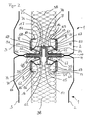
- a wall element 1 has a noise barrier
- two wall panels 2, 3 made of sheet metal, each along two opposite Plate edges 4, 5 and 6, 7 via a snap connection with a Profile bar 8, 9 are connected from plastic.
- a spring 10, 11, 12 or 13 integrally formed On each of the two opposite plate edges 4, 5, 6 and 7 respectively respective wall plate 2 or 3 is a spring 10, 11, 12 or 13 integrally formed, which extends over the entire length of the their assigned plate edges 4, 5, 6 and 7 extends.
- the Springs 10, 11 and 12, 13 are relative to the associated Wall plate 2 or 3 at an angle of 90 ° to the same side angled and each engage in one of the assigned Profile bar 8, 9 formed longitudinal groove 14, 15, 16, 17 a.
- the opposite springs 10, 11 and 12, 13 of the respective Wall plates 2 and 3 face each other, i.e.
- each one Leg spring with an elastic resilient to the outside form inner leg 18, 19, 20, 21.
- the outer leg 22, 23, 24, 25 of the respective leg spring is in one piece on the associated plate edge 4, 5, 6 and 7 connected.
- each Leg spring engages in an associated longitudinal groove 14, 15, 16 and 17 formed undercut 26, 27, 28, 29 on.
- a parallel to the wall panels 2, 3 towards the outside angled end section 30, 31, 32, 33 of the respective resilient inner leg 18, 19, 20, 21 lies, as also shown more clearly in Figure 3, on the outer Side boundary wall 34, 35, 36, 37 of the associated Undercut 26, 27, 28 and 29, so that the respective Wall plate 2, 3 against falling out of the side Profile strips 8, 9 is locked.
- the two wall plates 2, 3 are each by bends 39, 40 in the middle and through bends 41, 42 and 43, 44 adjacent to the plate edges 4, 5 and 6, 7 stiffened.
- the profile of the profile strips 8, 9 is based on FIG. 2 explains in which two adjacent wall elements 1 shown connected to each other in a horizontal section are.
- the two profile strips 8, 9 each have an open profile with two opposite to each other at 90 ° to the vertical flange sections 45, 46 and 47 angled to the side, 48 on which a lower or an upper boundary wall of the associated longitudinal groove 14, 17 and 15, 16 form.
- this vertically running profile sections i.e.
- Adjacent and opposite to the respective outer Side boundary wall 34, 37 and 35, 36 is on the assigned upper 53, 54 and lower 55, 56 boundary wall one that extends vertically upwards or downwards Profile section formed, which is a lateral Boundary wall 57, 58 and 59, 60 of a U-shaped rail 61 or 62 forms, the bottom wall in sections of the associated upper 53, 54 and lower 55, 56 boundary walls is formed.
- Boundary walls 57, 58 and 59, 60 of the respective U-profile rail 61, 62 of the associated profile strip 8 or 9 includes an angled 90 ° to the inside Profile section 63, 64 or 65, 66, which is therefore parallel to the upper 53, 54 and lower 55, 56 boundary walls runs and which is shorter than this.
- outer side boundary wall 34, 37 or 35, 36 of the respective undercut 26, 29 or 27, 28 closes at the outer end of the assigned upper or lower boundary wall 53, 54 and 55, 56 an outside parallel to the associated lateral boundary wall 57, 58 or 59, 60 of the respective U-profile rail 61 or 62 extending outer profile section 67, 68 or 69, 70 such indicates that between the respective lateral boundary wall 57, 58, 59, 60 and the associated outer profile section 67, 68, 69, 70 a longitudinal slot 71, 72, 73, 74 is formed, which is along the assigned profile bar 8 or 9 extends.
- adjacent wall elements 1 can also be used spring 78 engaging in the groove 78 open to the outside be connected to each other, the two Flange sections 45, 46 and 47, 48 of the respective Profile strips 8 and 9 lie on top of each other.
- the springs 10, 11 and 12, 13 lie with their on the associated wall plate 2 or 3 connected outer Legs 22, 23, 24 and 25 with its outside on the Inside of the associated flange section 45, 47 or 48, 46 the profile strips 8, 9. So that the wall plates 2, 3 above and below of the respective profile bar 9 and 8 respectively whose flange sections 47, 48 and 45, 46 are supported.
- the Feathers 10, 11, 12, 13 are also with her from her Angular shape, i.e. Tab shape, resulting arc section the inner side boundary wall 49, 50, 51, 52 of the assigned longitudinal groove 14, 15, 16 and 17, so that the associated wall plate 2, 3 laterally supported from the inside is.
- the wall plates 2, 3 are thus free of play from the two Profile strips 8, 9 supported, the two elastic compliant, inner legs 19, 20 of the associated, tab-shaped springs 11, 12 with their free end portion against the associated lower boundary wall 55, 56 of the assigned longitudinal groove 15, 16 in the installed position of the Wandlelements 1 upper profile bar 9 are pressed elastically, and wherein the two resilient inner legs 18, 21 of the associated tab-shaped springs 10, 13 with their free end section against the assigned upper Boundary wall 53, 54 of the associated longitudinal groove 14, 17 of the in Installation position of the converter element 1 lower profile strip 8 elastic are pressed.
- the noise insulation panel 38 of the respective wall element 1 is on the edge in the U-profile rails 61, 62 with a positive fit used.
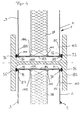
- FIG 3 shows two wall elements 1 connected to one another another embodiment of the invention.
- This Wall elements 1 correspond to those from FIGS. 1 and 2 apparent wall elements 1 with the exception that this Embodiment of two profile strips 8, 9 at the top or lower outer side an outwardly open longitudinal groove 78 or 79 is formed.
- Both wall elements are as one Spring-serving strip 80 with a rectangular cross section connected to each other, which in the longitudinal grooves 78, 79th intervenes.
- the respective wall element 1 is in this Embodiment provided with a cover plate 81, which is parallel to the wall panels 2, 3 and to the noise insulation panel 38 extends and which edge in the in Figure 3 on the left side of the respective U-profile rail 61 or 62 on the Outside of the assigned lateral boundary wall 58 or 60 provided longitudinal slot 72 and 74 is used.
- FIG 4 is a horizontal section of two on an H-profile post 82 connected wall elements 1 shown.
- the wall elements extend with horizontal ones Profile strips between the H-profile posts and are on the edge into the respective U-profile section of the H-profile post 82 used.
- On the end faces of the respective wall element 1 is a cover plate 83, 84 made of plastic arranged, which on the assigned profile bar-free Plate edges 85, 86, 87, 88 of the wall plates 2, 3 of their Front side is plugged in and the two opposing plates 2, 3 connects together.
- cover plates 83, 84 to be able to be plugged on are parallel to their longitudinal edges the side edges of the assigned panels that are free of profiled strips 2, 3 extending grooves 97, 98, 99, 100 are provided, in which engage the plates 2, 3 on the edge.
- each cover plate 83, 84 each two vertically (in the installed position of wall element 1) extending grooves 101, 102, 103, 104 provided, of which the respective groove 101 and 104 of a cover plate 83 with the assigned groove 102 or 103 of the opposite Cover plate 84 is aligned, and these two each grooves 101, 102 or 103, 104 aligned with one another with the assigned to both, each vertically one another opposite longitudinal slots 71, 73 and 72, 74 in the Profile strips 8, 9 are aligned.
- FIG 5 is to cover the front of the Wall element 1 provided cover plate 83, 84 in front and Side view shown.
- the cover plate 83, 84 is in their Front view (left in Figure 5) rectangular and in their longitudinal center with a plurality of in the longitudinal direction Cover plate 83, 84 aligned, rectangular through holes 105 provided.
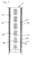
- FIG. 6 shows a longitudinal section through an H-profile post 82 shown with the wall element 1 inserted therein.
- the through holes 105 are in the Cover plate 83 in front of the end face of soundproofing plate 38.
- This allows in the cavity 106 (see Figure 4) between the Wall element 1 and the H-profile post sound waves through the cover 83 on the end face into the sound insulation plate 83 penetrate and be absorbed by this.
- the elongated rubber buffers 93, 96 on the side edges 89 and 90 of the cover plate 83 seal as explained above and also prevent damage to the posts 82 and Wall element 1 when inserting the same between the posts 82.
- the profile strips 8, 9 not shown in FIG. 6 extend perpendicular to the in the H-profile posts 82nd used wall element edges and thus run horizontally between the posts 82.
- the wall element is accordingly preferably cuboid with rectangular wall panels 2, 3 and rectangular cover plates 83, 84.
Landscapes
- Engineering & Computer Science (AREA)
- Architecture (AREA)
- Civil Engineering (AREA)
- Structural Engineering (AREA)
- Building Environments (AREA)
- Finishing Walls (AREA)
Abstract
Description
- 1
- Wandelement
- 2, 3
- Wandplatten
- 4, 5, 6, 7
- Plattenränder
- 8, 9
- Profilleisten
- 10, 11, 12, 13
- Federn (Schenkelfedern)
- 14, 15, 16, 17
- hinterschnittene Nuten
- 18, 19, 20, 21
- elastisch nachgiebiger, innerer Schenkel der Schenkelfedern
- 22, 23, 24, 25
- äußerer Schenkel der Schenkelfedern
- 26, 27, 28, 29
- Hinterschneidungen
- 30, 31, 32, 33
- Endabschnitt der Schenkelfedern
- 34, 35, 36, 37
- Seitenbegrenzungswand der Hinterschneidungen
- 38
- Lärmdämmplatte
- 39, 30, 41,
- Abkantungen
- 42, 43, 44
- Abkantungen
- 45, 46, 47, 48
- Flanschabschnitte
- 49, 50, 51, 52
- innere Seitenbegrenzungswand der Längsnuten
- 53, 54, 55, 56
- obere und untere Begrenzungswand der Längsnuten
- 57, 58, 59, 60
- seitliche Begrenzungswand der U-Profilschienen
- 61, 62
- U-Profilschienen
- 63, 64, 65, 66
- abgewinkelter Profilabschnitt
- 67, 68, 69, 70
- äußerer Profilabschnitt
- 71, 72, 73, 74
- Längsschlitz
- 75
- Vorsprungsabschnitt
- 76
- Paßfeder
- 77
- Vertiefung
- 78, 79
- Längsnut
- 80
- Leiste
- 81
- Abdeckplatte
- 83, 84
- Abdeckplatte
- 85, 86, 87, 88
- profilleistenfreie Ränder der Wandplatten
- 89, 90, 91, 92
- vertikal verlaufende Seitenränder
- 93, 94, 95, 96
- Gummipuffer
- 97, 98, 99, 100
- parallel zu profilleistenfreien Rändern verlaufende Nuten
- 101, 102, 103, 104
- vertikal verlaufende Nuten
- 105
- rechteckige Durchgangslöcher
- 106
- Hohlraum
- 107
- Spalt
Claims (13)
- Wandelement (1) einer Lärmschutzwand, die aus neben- und/oder übereinander angeordneten, zwischen Pfosten (82) festgelegten Wandelementen (1) aufgebaut ist, mit zwei gegenüberliegend im Abstand voneinander angeordneten, parallelen Wandplatten (2, 3) und zwei Profilleisten (8,9 ), über welche die beiden Wandplatten (2, 3) jeweils entlang zweier einander gegenüberliegender Plattenränder (4, 5 bzw. 6, 7) miteinander verbunden sind, an denen elastische Federn (10, 11 bzw. 12, 13) ausgebildet sind, welche in jeweils eine von der Profilleiste (8, 9) gebildete, hinterschnittene Längsnut (14, 15 bzw. 16, 17) eingerastet sind.
- Wandelement (1) nach Anspruch 1, wobei die Federn (10, 11, 12, 13) an den Wandplatten (2, 3) seitlich angeordnet sind.
- Wandelement (1) nach Anspruch 1 oder 2, wobei die Federn (10, 11, 12, 13) an dem jeweiligen Plattenrand (4, 5, 6 bzw. 7) einstückig angeformt und als vom Plattenrand (4, 5, 6, 7) zur Seite hin abgewinkelte, laschenförmige Schenkelfedern ausgebildet sind.
- Wandelement (1) nach einem der Ansprüche 1 bis 3, wobei die Wandplatten (2, 3) aus rostfreiem Blech sind.
- Wandelement (1) nach einem der Ansprüche 1 bis 4, wobei eine zwischen den beiden Wandplatten (2, 3) parallel zu diesen sowie im Abstand von beiden angeordnete Schalldämmplatte (38) randseitig an den beiden Profilleisten (8, 9) befestigt ist, und wobei in einer der beiden Wandplatten (2, 3) eine Mehrzahl von Durchgangslöchern ausgebildet ist.
- Wandelement (1) nach Anspruch 5, wobei von den Profilleisten (8, 9) an ihrer Innenseite jeweils eine U-Profilschiene (61 bzw. 62) gebildet ist, in welche die Schalldämmplatte (38) jeweils randseitig eingesetzt ist.
- Wandelement (1) nach Anspruch 5 oder 6, wobei beide Wandplatten (2, 3) mit Durchgangslöchern versehen sind, und wobei von der jeweiligen Profilleiste (8,9) an der Außenseite einer seitlichen Begrenzungswand (58 bzw. 60) der U-Profilschiene (61 bzw. 62) ein Längsschlitz (72 bzw. 74) gebildet ist, in welchen eine die Schalldämmplatte (38) abdeckende Trennplatte (81) randseitig eingesetzt ist.
- Wandelement (1) nach einem der Ansprüche 1 bis 7, wobei an den profilleistenfreien Plattenrändern (85, 86, 87, 88) der Wandplatten (2, 3) eine die zugehörige seitliche Stirnfläche des Wandelements (1) abdeckende Abdeckplatte (83, 84) angebracht ist.
- Wandelement (1) nach einem der Ansprüche 1 bis 8, ferner aufweisend: Kunststoffpuffer (93, 94, 95, 96), welche entlang der profilleistenfreien Ränder des Wandelements (1) außenseitig angeordnet sind.
- Wandelement (1) nach einem der Ansprüche 1 bis 9, wobei von den Profilleisten (8, 9) an ihrer Außenseite derart eine Paßfeder (76) bzw. eine Längsnut (78) gebildet ist, daß einander benachbarte Wandelemente (1) mit in die Längsnut (78) formschlüssig eingreifender Paßfeder (76) aneinander anschließbar sind.
- Wandelement (1) nach einem der Ansprüche 1 bis 9, wobei von den beiden Profilleisten (8, 9) an ihrer Außenseite jeweils eine Längsnut (78) gebildet ist.
- Wandelement (1) nach einem der Ansprüche 1 bis 11, wobei von den Profilleisten (8, 9) an ihrer Außenseite ein sich in ihrer Längsrichtung erstreckender Flansch (45, 46 bzw. 47, 48) gebildet ist, über welchen benachbarte Wandelemente (1) aneinander anschließbar sind.
- Lärmschutzwand (1) mit einer Mehrzahl von Wandelementen (1) nach einem der Ansprüche 1 bis 12, wobei die Wandelemente (1) mit sich horizontal erstreckenden Profilleisten (8, 9) zwischen benachbarte H-Profil-Pfosten (82) eingesetzt sind.
Applications Claiming Priority (2)
| Application Number | Priority Date | Filing Date | Title |
|---|---|---|---|
| DE19816089 | 1998-04-09 | ||
| DE1998116089 DE19816089A1 (de) | 1998-04-09 | 1998-04-09 | Wandelement für eine Lärmschutzwand und Lärmschutzwand |
Publications (2)
| Publication Number | Publication Date |
|---|---|
| EP0949382A2 true EP0949382A2 (de) | 1999-10-13 |
| EP0949382A3 EP0949382A3 (de) | 2001-01-17 |
Family
ID=7864228
Family Applications (1)
| Application Number | Title | Priority Date | Filing Date |
|---|---|---|---|
| EP99107018A Withdrawn EP0949382A3 (de) | 1998-04-09 | 1999-04-09 | Wandelement für eine Lärmschutzwand und Lärmschutzwand |
Country Status (2)
| Country | Link |
|---|---|
| EP (1) | EP0949382A3 (de) |
| DE (1) | DE19816089A1 (de) |
Cited By (2)
| Publication number | Priority date | Publication date | Assignee | Title |
|---|---|---|---|---|
| EP1659222A1 (de) * | 2004-11-17 | 2006-05-24 | Gerd Heltriegel | Schallelement, Schallschutzwand und Verfahren zur Herstellung des Schallelements |
| WO2015104438A1 (es) * | 2014-01-09 | 2015-07-16 | Metalesa Branding, S.L. | Dispositivo para el ajuste de paneles acústicos |
Citations (5)
| Publication number | Priority date | Publication date | Assignee | Title |
|---|---|---|---|---|
| FR2438313A1 (fr) * | 1978-10-06 | 1980-04-30 | Kloeckner Werke Ag | Paroi de protection contre le bruit |
| DE8008907U1 (de) * | 1980-03-31 | 1981-09-17 | Naamloze Vennootschap Hörmann-Belgie, 3600 Genk | Kastenförmiges Element zum Aufbau schallschützender Wände |
| CH672932A5 (en) * | 1987-07-28 | 1990-01-15 | Montana Stahl Ag | Noise-attenuating wall section - contains insulating layers of different densities, with first layer held clear of front wall by distance piece |
| DE29609237U1 (de) * | 1996-05-23 | 1996-08-14 | Koch Gmbh & Co Kg | Wandelement zur Errichtung von Schutzwänden |
| GB2313866A (en) * | 1996-06-07 | 1997-12-10 | Hill & Smith Ltd | Panel and barrier system incorporating same |
Family Cites Families (5)
| Publication number | Priority date | Publication date | Assignee | Title |
|---|---|---|---|---|
| DE2937446C2 (de) * | 1979-09-15 | 1982-01-21 | Klöckner-Werke AG, 4100 Duisburg | Lärmschutzwand |
| DE3012514A1 (de) * | 1980-03-31 | 1981-10-08 | Naamloze Vennootschap Hörmann-Belgie, 3600 Genk | Kastenfoermiges element zum aufbau schallschuetzender waende |
| DE3236235C2 (de) * | 1982-09-30 | 1985-11-14 | Reckendrees GmbH Rolladen- und Kunststoffensterfabrik, 4836 Herzebrock | Sicht- und Schallschutzwand |
| DE8300026U1 (de) * | 1983-01-03 | 1983-04-21 | Colberg, Norbert, 3150 Peine | Paneel einer laermschutzwand oder laermschutzverkleidung |
| DE9105831U1 (de) * | 1991-05-10 | 1991-08-08 | Colberg Metall-, Stahl- Und Kunststofftechnik Gmbh, 3150 Peine, De |
-
1998
- 1998-04-09 DE DE1998116089 patent/DE19816089A1/de not_active Ceased
-
1999
- 1999-04-09 EP EP99107018A patent/EP0949382A3/de not_active Withdrawn
Patent Citations (5)
| Publication number | Priority date | Publication date | Assignee | Title |
|---|---|---|---|---|
| FR2438313A1 (fr) * | 1978-10-06 | 1980-04-30 | Kloeckner Werke Ag | Paroi de protection contre le bruit |
| DE8008907U1 (de) * | 1980-03-31 | 1981-09-17 | Naamloze Vennootschap Hörmann-Belgie, 3600 Genk | Kastenförmiges Element zum Aufbau schallschützender Wände |
| CH672932A5 (en) * | 1987-07-28 | 1990-01-15 | Montana Stahl Ag | Noise-attenuating wall section - contains insulating layers of different densities, with first layer held clear of front wall by distance piece |
| DE29609237U1 (de) * | 1996-05-23 | 1996-08-14 | Koch Gmbh & Co Kg | Wandelement zur Errichtung von Schutzwänden |
| GB2313866A (en) * | 1996-06-07 | 1997-12-10 | Hill & Smith Ltd | Panel and barrier system incorporating same |
Cited By (2)
| Publication number | Priority date | Publication date | Assignee | Title |
|---|---|---|---|---|
| EP1659222A1 (de) * | 2004-11-17 | 2006-05-24 | Gerd Heltriegel | Schallelement, Schallschutzwand und Verfahren zur Herstellung des Schallelements |
| WO2015104438A1 (es) * | 2014-01-09 | 2015-07-16 | Metalesa Branding, S.L. | Dispositivo para el ajuste de paneles acústicos |
Also Published As
| Publication number | Publication date |
|---|---|
| DE19816089A1 (de) | 1999-10-21 |
| EP0949382A3 (de) | 2001-01-17 |
Similar Documents
| Publication | Publication Date | Title |
|---|---|---|
| EP0939984B1 (de) | Schaltschrank | |
| DE2657648A1 (de) | Schallschutzwand | |
| WO2003012947A1 (de) | Rahmengestell | |
| EP1557519B1 (de) | Rahmenkörper aus einem hohlen, stranggepressten Kunststoffprofil für Fenster und Türen | |
| DE2935745C2 (de) | Lärmschutzwand | |
| EP0949382A2 (de) | Wandelement für eine Lärmschutzwand und Lärmschutzwand | |
| CH685357A5 (de) | Lüftungsvorrichtung für Räume. | |
| EP1787002B1 (de) | Bauteilesatz aus wenigstens einer sprosse und wenigstens zwei sprossenendstücken zum einbauen in eine isolierglasscheibe | |
| EP2946043A1 (de) | Bauprofilelement | |
| DE3012514A1 (de) | Kastenfoermiges element zum aufbau schallschuetzender waende | |
| DE2423234A1 (de) | Rahmenloses gehaeuse | |
| CH663079A5 (de) | Lueftungsvorrichtung fuer den einbau in eine fenster-, tuer- oder andere wandoeffnung eines gebaeudes. | |
| DE2618836A1 (de) | Schallschutzwand | |
| EP0745732B1 (de) | Kragplattenelement gegen Kältebrücken | |
| DE2116116A1 (de) | Bauelement zur Schallabsorption | |
| DE3236235A1 (de) | Sicht- und schallschutzwand | |
| DE2213777A1 (de) | Schallschutzwand | |
| DE8008907U1 (de) | Kastenförmiges Element zum Aufbau schallschützender Wände | |
| DE2850588A1 (de) | Schalldaemmendes bauelement | |
| DE3343260C2 (de) | Plattenartiges Bauteil und Verfahren zu seiner Herstellung | |
| EP4001531A1 (de) | Bausatz für ein gerätehaus | |
| DE7834713U1 (de) | Schalldaemmendes bauelement | |
| EP2521815A1 (de) | Lärmschutzelement und lärmschutzwand | |
| DE2235863A1 (de) | Schallabsorptionswand, insbesondere zur verminderung der geraeuschbelaestigung an strassen | |
| DE2101233C3 (de) | Lärmschutzwand insbesondere für Straßen, Flugplätze u. dgl. sowie Verfahren zu Ihrer Herstellung |
Legal Events
| Date | Code | Title | Description |
|---|---|---|---|
| PUAI | Public reference made under article 153(3) epc to a published international application that has entered the european phase |
Free format text: ORIGINAL CODE: 0009012 |
|
| AK | Designated contracting states |
Kind code of ref document: A2 Designated state(s): AT BE CH CY DE DK ES FI FR GB GR IE IT LI LU MC NL PT SE |
|
| AX | Request for extension of the european patent |
Free format text: AL;LT;LV;MK;RO;SI |
|
| PUAL | Search report despatched |
Free format text: ORIGINAL CODE: 0009013 |
|
| AK | Designated contracting states |
Kind code of ref document: A3 Designated state(s): AT BE CH CY DE DK ES FI FR GB GR IE IT LI LU MC NL PT SE |
|
| AX | Request for extension of the european patent |
Free format text: AL;LT;LV;MK;RO;SI |
|
| AKX | Designation fees paid | ||
| REG | Reference to a national code |
Ref country code: DE Ref legal event code: 8566 |
|
| STAA | Information on the status of an ep patent application or granted ep patent |
Free format text: STATUS: THE APPLICATION IS DEEMED TO BE WITHDRAWN |
|
| 18D | Application deemed to be withdrawn |
Effective date: 20010718 |