EP1557519B1 - Rahmenkörper aus einem hohlen, stranggepressten Kunststoffprofil für Fenster und Türen - Google Patents
Rahmenkörper aus einem hohlen, stranggepressten Kunststoffprofil für Fenster und Türen Download PDFInfo
- Publication number
- EP1557519B1 EP1557519B1 EP05000952A EP05000952A EP1557519B1 EP 1557519 B1 EP1557519 B1 EP 1557519B1 EP 05000952 A EP05000952 A EP 05000952A EP 05000952 A EP05000952 A EP 05000952A EP 1557519 B1 EP1557519 B1 EP 1557519B1
- Authority
- EP
- European Patent Office
- Prior art keywords
- limb
- hollow profile
- toothing
- frame member
- limbs
- Prior art date
- Legal status (The legal status is an assumption and is not a legal conclusion. Google has not performed a legal analysis and makes no representation as to the accuracy of the status listed.)
- Not-in-force
Links
Images

Classifications
-
- E—FIXED CONSTRUCTIONS
- E06—DOORS, WINDOWS, SHUTTERS, OR ROLLER BLINDS IN GENERAL; LADDERS
- E06B—FIXED OR MOVABLE CLOSURES FOR OPENINGS IN BUILDINGS, VEHICLES, FENCES OR LIKE ENCLOSURES IN GENERAL, e.g. DOORS, WINDOWS, BLINDS, GATES
- E06B1/00—Border constructions of openings in walls, floors, or ceilings; Frames to be rigidly mounted in such openings
- E06B1/04—Frames for doors, windows, or the like to be fixed in openings
- E06B1/32—Frames composed of parts made of different materials
-
- E—FIXED CONSTRUCTIONS
- E06—DOORS, WINDOWS, SHUTTERS, OR ROLLER BLINDS IN GENERAL; LADDERS
- E06B—FIXED OR MOVABLE CLOSURES FOR OPENINGS IN BUILDINGS, VEHICLES, FENCES OR LIKE ENCLOSURES IN GENERAL, e.g. DOORS, WINDOWS, BLINDS, GATES
- E06B1/00—Border constructions of openings in walls, floors, or ceilings; Frames to be rigidly mounted in such openings
- E06B1/04—Frames for doors, windows, or the like to be fixed in openings
- E06B1/26—Frames of plastics
- E06B1/30—Frames of plastics composed of several parts with respect to the cross-section of the frame itself
-
- E—FIXED CONSTRUCTIONS
- E06—DOORS, WINDOWS, SHUTTERS, OR ROLLER BLINDS IN GENERAL; LADDERS
- E06B—FIXED OR MOVABLE CLOSURES FOR OPENINGS IN BUILDINGS, VEHICLES, FENCES OR LIKE ENCLOSURES IN GENERAL, e.g. DOORS, WINDOWS, BLINDS, GATES
- E06B1/00—Border constructions of openings in walls, floors, or ceilings; Frames to be rigidly mounted in such openings
- E06B1/62—Tightening or covering joints between the border of openings and the frame or between contiguous frames
Definitions
- the invention relates to a frame body made of a hollow, extruded, in particular consisting of PVC plastic profile for windows and doors with the features of the preamble of claim 1.
- Document GB-A-2 341 410 discloses a frame body according to the preamble.
- the oblique outer wall of the hollow profile leg surrounding the panel contributes to better cleaning of the window construction.
- the invention has set itself the task of developing a fernsterrahmenprofilianus that can be shortened without losing this (self) cleaning property.
- the window frame body 1 shown in Fig. 1 consists of a hollow, extruded PVC profile with two mutually parallel and perpendicular and a Schaumstoffpaneel Sciences 2 surrounding hollow profile legs 3, 4, which are connected by a horizontal hollow profile part 5 to an approximately Z-profile.
- the horizontal hollow profile part 5 has a horizontal receiving groove 6 for the one of two legs 7, 8 of an existing metal frame 9.
- the two legs 7, 8 of the frame are approximately at right angles to each other.
- the thigh. 7 is received by the receiving groove 6, the surface 10 is provided with a corrugation or toothing 11 which is engageable with a surface toothing 12 of said one leg 7 in clamping engagement, as soon as the leg 7 is pressed into the receiving groove.
- FIG. 2 The toothing 11 of the surface 10 of the receiving groove 6 and the surface toothing 12 of the first leg 7 of the frame 9 are shown in FIG. 2 of obliquely placed teeth, which engage in the apparent from Fig. 1 insertion state of the frame 9 into each other and lock it with the profile body 1 ,
- both the receiving groove 6 and the frame 9 have a helical toothing.
- the toothing of the surface of the receiving groove or the surface toothing of the first leg of obliquely set teeth so that in the latter case, a combination of slanted teeth and straight teeth is possible.
- the obliquely placed teeth may be located in the region of the receiving groove or preferably on the frame, namely on the leg 7 of the frame 9.
- the leg 7 of the window frame 9 which can be inserted into the receiving groove 6 is provided on both sides with the surface toothing 12. Likewise, the receiving groove 6 on both sides of the toothing 11 in the region of its surface 10.
- the surface 10 of the receiving groove is only partially, preferably on one side, and the surface toothing 12 of the leg 7 at least partially, preferably one-sided, provided with the toothing or corrugation. It is clear that provided with the teeth surfaces of receiving groove and legs in the insertion state of the leg into the receiving groove facing each other, so that the teeth can act on each other and the leg and thus the entire frame is fixed in the inserted state.
- the teeth are inclined at approximately 45 ° and formed like a sawtooth with a steeply rising flank and an adjoining shallow sloping flank.
- 2 shows that the obliquely set teeth in the region of the receiving groove 6 each have a flank which rises steeply to the left and a flatter falling flank which adjoins the right.
- the leg 7 of the frame 1 teeth in which the steeply sloping edge are arranged on the right and the adjoining, gently sloping edge to the left.
- the leg 7 in the direction of arrow A can be inserted easily into the receiving groove 6; due to the tooth structure and the relative disposition of the teeth in the inserted state the leg 7 of the frame 9 can be relatively easily inserted or inserted into the receiving groove; However, the leg is reliably prevented from sliding out of the receiving groove due to the adjacent vertical tooth flanks. It is therefore not readily possible to pull the frame opposite to the insertion according to arrow A from the receiving groove 6.
- the height of the receiving groove 6 corresponds to the thickness of the leg 7 or differs slightly from the thickness of the leg 7, wherein the deviation in the range 0.1 to 0.7 mm, preferably 0.1 to 0.4 mm.
- the lower boundary wall 14 of the receiving groove 6 corresponds to the lower wall of the horizontal hollow profile part 5, and this wall rests on the Schaumstoffpaneel Sciences 2, which is also shown cut in the figures.
- the length of the receiving groove 6 is at least as large as the length of the inserted into it leg 7 of the window frame.
- the length of the leg 7 is in turn dimensioned so that the other leg 8 of the frame completely rests in the illustrated installation or insertion of the first leg on the surface 15 of the Schaumstoffpaneel stressess 2, wherein on the Schaumstoffpaleel endeavor a contact pressure is exerted, which the the panel body. 2 at least partially surrounding vertical hollow profile leg 3 presses against the surface of the panel body.
- Blendrahmenschenkels 7 is ensured on the surface of Schaumstoffpaneel Sciencess 2, in view of the special design of the surfaces of the frame frame legs and, if necessary, on the Schaumstoffpaneel Sciences 2 adjacent outer walls 25, 26 of the frame profile body, which will be explained below, is particularly durable and prevents destruction of the permanent connection between the frame and window frame profile body even with significant temperature fluctuations and other weather-related influences.
- a vertical hollow profile leg 3 and this with the other vertical hollow profile leg 2 connecting horizontal hollow profile part 5 each have one adjacent to the Schaumstoffpaneel Sciences 2 surface 31, 32 which is at least partially interlocked with the Schaumstoffpaneel Sciences 2 or by roughening or Corrugation is mechanically connected and helps ensure that an adhesive introduced between profile body 1 and 2 panel adhere better.
- the two vertical hollow profile legs 3, 4 and the horizontal hollow profile part 5 form a uniform whole and have cavities 16 to 21, which are closed to the outside and are at least partially stiffened by insert body, not shown, for example, made of metal.
- the cavities 16-21 of the hollow profile legs form chambers which are delimited by intermediate walls 22, 23 which separate and stiffen the outer walls 24, 25 of the hollow profile legs 3, 4 at a distance from one another and at least partially aligned at an angle with respect to the surfaces of these outer walls are in the illustrated embodiment ⁇ or> as 90 ° and corresponds to the angle at which the outer, the hollow profile legs 3, 4 and last chamber 16 final outer wall 30 extends.
- the intermediate walls 22, 23 extend parallel to the closing outer wall 30th
- the oblique outer wall 30 is circumferentially closed in the welded state and contributes substantially to better cleaning of the entire window construction in conjunction with the PU panel. This also applies to the fitting receiving groove 28 in the interior of the profile body.
- the oblique partition walls 22, 23 in the profile body 1 enable to shorten the profile leg 3, without losing the self-cleaning property.
- Such shortening of the profile body may be required, for example, in tight installation dimensions, if steel beams or concrete pillars are located too close to the window or on the door.
- a bending and torsion-resistant body is created, in particular in conjunction with the inserted into the receiving groove 6 frame, which is advantageously different from known window frame bodies of the type mentioned that he can be produced without major manufacturing and cost, yet Especially since the frame 9 only needs to be pressed into the receiving groove to produce a tight fit due to the corrugation or other mechanical surface structures of the contacting surfaces, its further particular advantage is that the frame the window frame of the profile body to the SchaumstoffpaneelSystem so that usually additional screwing of the sash body with the foam panel body can be avoided.
- the closure 27 of the upper groove 28 of the window frame body 1 and in particular its vertical leg 3 forms the possibility of securing the frame body against dirt particles penetrating from the outside and thereby keeping the profile body clean.
- the seal 29 located in the upper region of the hollow profile limb 4 is in the customary manner in a groove provided in the frame profile body 1 arranged, so that the window sash or door leaf, not shown, can be pressed tightly against the frame profile body 1 and penetration of moisture, especially rainwater, is prevented.
- the plastic profile according to the invention has a particular resistance to deflection due to wind pressure and wind suction and can be stiffened if necessary with steel profiles of different thickness, which are installed in the profiled body cavities, in addition.
- the stiffening of the construction in conjunction with the foamed PU panels 2 can be improved so that even can be dispensed with additional stiffening body as the steel profiles mentioned above.
- the upper double-walled version 33 of the two legs 3, 4 of the profile body 1 connecting hollow profile part 5 has the advantage of additional screwing of the profile, without being penetrated by this screw in the water leading level. Such a screw is particularly useful for extremely wide windows.
- the above frame body can be formed in adaptation to the respective panel thickness so that due to the inclined surface 34 of the frame 9 in the outer area can be dispensed with a window plate.
Landscapes
- Engineering & Computer Science (AREA)
- Civil Engineering (AREA)
- Structural Engineering (AREA)
- Wing Frames And Configurations (AREA)
- Extrusion Moulding Of Plastics Or The Like (AREA)
- Door And Window Frames Mounted To Openings (AREA)
- Securing Of Glass Panes Or The Like (AREA)
Description
- Die Erfindung betrifft einen Rahmenkörper aus einem hohlen, stranggepressten, insbesondere aus PVC bestehenden Kunststoffprofil für Fenster und Türen mit den Merkmalen des Oberbegriffs des Patentanspruchs 1.
- Das Dokument GB-A-2 341 410 offenbart einen Rahmenkörper gemäß des Oberbegriffs. Die schräge Aussenwand des das Paneel umgebenenden Hohlprofilschenkelsträgt zur besseren Reinigung der Fensterkonstruktion bei.
- Die Erfindung hat sich zur Aufgabe gemacht, einen fernsterrahmenprofilkörper zu entwickeln, der gekürzt werden kann, ohne diese (Selbst) Reinigungseigenschaft zu verlieren.
- Diese Aufgabe wird mit den Merkmale des kennzeichnenden Teils gelöst. Ausführungsbeispiele des Erfindungsgegenstandes werden nachfolgend anhand der Zeichnungen näher erläutert.
- Es zeigen:
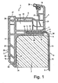
- Fig. 1
- einen schematischen Schnitt durch einen Rahmenkörper mit Blendrahmen im zusammengebauten Zustand gemäß einer ersten Ausführungsform; und
- Fig. 2
- einen schematischen Schnitt durch Rahmenkörper und Blendrahmen im auseinander gezogenen Zustand gemäß einer anderen Ausführungsform.
- Der in Fig. 1 gezeigte Fensterrahmenkörper 1 besteht aus einem hohlen, stranggepressten PVC-Profil mit zwei parallel zueinander und senkrecht verlaufenden sowie einen Schaumstoffpaneelkörper 2 umgebenden Hohlprofilschenkeln 3, 4, die durch einen waagerechten Hohlprofilteil 5 zu einem annähernd Z-Profil verbunden sind. Der waagerechte Hohlprofilteil 5 weist eine waagerechte Aufnahmenut 6 für den einen von zwei Schenkeln 7, 8 eines aus Metall bestehenden Blendrahmens 9 auf. Die beiden Schenkel 7, 8 des Blendrahmens verlaufen in etwa rechtwinklig zueinander. Der Schenkel. 7 wird von der Aufnahmenut 6 aufgenommen, deren Oberfläche 10 mit einer Riffelung oder Verzahnung 11 versehen ist, die mit einer Oberflächenverzahnung 12 des genannten einen Schenkels 7 in Klemmeingriff bringbar ist, sobald der Schenkel 7 in die Aufnahmenut hineingedrückt wird.
- Die Verzahnung 11 der Oberfläche 10 der Aufnahmenut 6 und die Oberflächenverzahnung 12 des ersten Schenkels 7 des Blendrahmens 9 bestehen gemäß Fig. 2 aus schräg gestellten Zähnen, die im aus Fig. 1 ersichtlichen Einsteckzustand des Blendrahmens 9 ineinander greifen und diesen mit dem Profilkörper 1 arretieren.
- Gemäß dem in Fig. 2 gezeigten Ausführungsbeispiel weisen sowohl die Aufnahmenut 6 als auch der Blendrahmen 9 eine Schrägverzahnung auf. Gemäß einer anderen, nicht gezeigten Ausführungsform der Erfindung können die Verzahnung der Oberfläche der Aufnahmenut oder die Oberflächenverzahnung des ersten Schenkels aus schräg gestellten Zähnen bestehen, so dass in dem letztgenannten Fall auch eine Kombination von schräg gestellten Zähnen und gerade gestellten Zähnen möglich ist. Die schräg gestellten Zähne können sich im Bereich der Aufnahmenut oder vorzugsweise am Blendrahmen, nämlich am Schenkel 7 des Blendrahmens 9, befinden.
- Bei der in Fig. 1 gezeigten Ausführungsform der Erfindung ist der in die Aufnahmenut 6 einsteckbare Schenkel 7 des Blendrahmens 9 beidseitig mit der Oberflächenverzahnung 12 versehen. Ebenso weist die Aufnahmenut 6 beidseits die Verzahnung 11 im Bereich ihrer Oberfläche 10 auf.
- Gemäß der in Fig. 2 gezeigten, anderen Ausführungsform der Erfindung ist die Oberfläche 10 der Aufnahmenut lediglich teilweise, vorzugsweise einseitig, und die Oberflächenverzahnung 12 des Schenkels 7 wenigstens teilweise, vorzugsweise einseitig, mit der Verzahnung oder Riffelung versehen. Es ist klar, dass die mit der Verzahnung versehenen Flächen von Aufnahmenut und Schenkel im Einsteckzustand des Schenkels in die Aufnahmenut zueinander weisen, so dass sich die Verzahnungen gegenseitig beaufschlagen können und sich der Schenkel und damit der gesamte Blendrahmen fest in dem eingesteckten Zustand befmdet.
- Bei der Schrägverzahnung sind die Zähne etwa 45° schräg gestellt und sägezahnartig mit einer steil aufragenden Flanke und einer sich daran anschließenden flacher abfallenden Flanke ausgebildet. Fig. 2 lässt erkennen, dass die schräg gestellten Zähne im Bereich der Aufnahmenut 6 jeweils eine links steil aufragende Flanke und eine rechts sich daran anschließende flacher abfallende Flanke haben. Umgekehrt hat der Schenkel 7 des Blendrahmens 1 Zähne, bei denen die steil abfallende Flanke rechts und die sich daran anschließende, flach abfallende Flanke nach links hin angeordnet sind.
- Somit ist der Schenkel 7 in Richtung des Pfeils A ohne weiteres in die Aufnahmenut 6 einschiebbar; aufgrund der Zahnstruktur und der relativen Anordnung der Zähne im Einsteckzustand kann der Schenkel 7 des Blendrahmens 9 relativ leicht in die Aufnahmenut eingeschoben bzw. eingesteckt werden; jedoch ist der Schenkel aufgrund der aneinander liegenden vertikal verlaufenden Zahnflanken sicher an einem Herausgleiten aus der Aufnahmenut gehindert. Es ist somit nicht ohne weiteres möglich, den Blendrahmen entgegen der Einsteckrichtung gemäß Pfeil A aus der Aufnahmenut 6 herauszuziehen.
- Es wird darauf hingewiesen, dass in Fig. 2 der Einfachheit halber größtenteils die einen Schnitt symbolisierenden Schraffuren weggelassen sind.
- Die Höhe der Aufnahmenut 6 entspricht der Dicke des Schenkels 7 oder weicht geringfügig von der Dicke des Schenkels 7 ab, wobei die Abweichung im Bereich 0,1 bis 0,7 mm, vorzugsweise 0,1 bis 0,4 mm, liegt. Die untere Begrenzungswand 14 der Aufnahmenut 6 entspricht der unteren Wand des waagerechten Hohlprofilteils 5, und diese Wand liegt auf dem Schaumstoffpaneelkörper 2 auf, der in den Figuren ebenfalls geschnitten dargestellt ist.
- Die Länge der Aufnahmenut 6 ist mindestens so groß wie die Länge des in sie eingesteckten Schenkels 7 des Blendrahmens. Die Länge des Schenkels 7 ist wiederum so bemessen, dass der andere Schenkel 8 des Blendrahmens im dargestellten Einbau- oder Einsteckzustand des ersten Schenkels auf der Oberfläche 15 des Schaumstoffpaneelkörpers 2 vollständig aufliegt, wobei auf den Schaumstoffpaneelkörper ein Anpressdruck ausgeübt wird, der den den Paneelkörper 2 zumindest teilweise umgebenden senkrechten Hohlprofilschenkel 3 an die Oberfläche des Paneelskörpers andrückt.
- Auf diese Weise ist ein fester Sitz sowohl des Fensterrahmenkörpers selbst als auch des in diesen bzw. dessen Aufnahmenut 6 hineingesteckten Blendrahmenschenkels 7 auf der Oberfläche des Schaumstoffpaneelkörpers 2 gewährleistet, der im Hinblick auf die besondere Ausbildung der Oberflächen der Blendrahmenschenkel und erforderlichenfalls auch der an dem Schaumstoffpaneelkörper 2 angrenzenden Außenwände 25, 26 des Rahmenprofilkörpers, welcher im folgenden noch erläutert wird, besonders dauerhaft ist und auch bei erheblichen Temperaturschwankungen und anderen witterungsbedingten Einflüssen eine Zerstörung der dauerhaften Verbindung zwischen Blendrahmen und Fensterrahmenprofilkörper verhindert.
- Zu diesen Ausgestaltungen gehört, dass der andere und damit senkrechte Schenkel 8 des Blendrahmens 9 auf wenigstens einem Teil seiner Oberfläche, die mit dem Schaumstoffpaneelkörper 2 in Berührung tritt, mit einer Oberflächenverzahnung oder Riffelung 13 versehen ist, die in der Zeichnung nur angedeutet ist.
- Dazu gehört ferner, dass der eine senkrechte Hohlprofilschenkel 3 und der diesen mit dem anderen senkrechten Hohlprofilschenkel 2 verbindende waagerechte Hohlprofilteil 5 je eine an dem Schaumstoffpaneelkörper 2 angrenzende Oberfläche 31, 32 aufweisen, die mit dem Schaumstoffpaneelkörper 2 wenigstens teilweise verzahnt oder durch Aufrauen oder Riffelung mechanisch verbunden ist und dazu beiträgt, dass ein zwischen Profilkörper 1 und Paneel 2 eingebrachter Kleber besser haftet.
- Die beiden senkrechten Hohlprofilschenkel 3, 4 und der waagerechte Hohlprofilteil 5 bilden ein einheitliches Ganzes und weisen Hohlräume 16 bis 21 auf, die nach außen verschlossen sind und zumindest teilweise durch nicht dargestellte Einlagekörper, beispielsweise aus Metall bestehend, versteift sind. Die Hohlräume 16 - 21 der Hohlprofilschenkel bilden Kammern, die durch Zwischenwände 22, 23 begrenzt sind, welche die Außenwände 24, 25 der Hohlprofilschenkel 3, 4 mit Abstand voneinander trennen und versteifen und zumindest teilweise in Bezug auf die Oberflächen dieser Außenwände unter einem Winkel ausgerichtet sind, der beim dargestellten Ausführungsbeispiel < bzw. > als 90° ist und dem Winkel entspricht, unter dem die äußere, die Hohlprofilschenkel 3, 4 bzw. letzte Kammer 16 abschließende Außenwand 30 verläuft. Somit verlaufen die Zwischenwände 22, 23 parallel zur abschließenden Außenwand 30.
- Die schräge Außenwand 30 ist im verschweißten Zustand umlaufend geschlossen und trägt im Wesentlichen zur besseren Reinigung der gesamten Fensterkonstruktion in Verbindung mit dem PU-Paneel bei. Dies gilt auch für die Beschlagaufnahmenut 28 im Inneren des Profilkörpers.
- Die schrägen Zwischenwände 22, 23 im Profilkörper 1 ermöglichenes, den Profilschenkel 3 zu kürzen, ohne dadurch die Selbstreinigungseigenschaft zu verlieren. Ein solches Kürzen des Profilkörpers kann beispielsweise bei knappen Einbaumaßen erforderlich sein, wenn Stahlträger oder Betonpfeiler zu nah am Fenster oder an der Tür angeordnet sind.
- Durch diese Konstruktion des Fensterrahmenkörpers wird insbesondere in Verbindung mit dem in die Aufnahmenut 6 eingesteckten Blendrahmen ein biege- und verwindungssteifer Körper geschaffen, der sich dadurch vorteilhaft von bekannten Fensterrahmenkörpern der eingangs genannten Art unterscheidet, dass er ohne größeren Fertigungs- und Kostenaufwand herstellbar ist, noch zumal der Blendrahmen 9 nur in die Aufnahmenut hingedrückt zu werden braucht, um aufgrund der Riffelung oder Verzahnung oder anderweitigen mechanischen Oberflächenstrukturen der einander berührenden Oberflächen einen festen Sitz zu erzeugen, dessen weiterer besonderer Vorteil darin besteht, dass der Blendrahmen den Fensterrahmen des Profilkörpers an den Schaumstoffpaneelkörper heranzieht, so dass gewöhnlich eine zusätzliche Verschraubung des Fensterrahmenkörpers mit dem Schaumstoffpaneelkörper vermieden werden kann.
- Darüber hinaus bildet der Verschluss 27 der oberen Nut 28 des Fensterrahmenkörpers 1 und insbesondere dessen senkrechten Schenkels 3 die Möglichkeit, den Rahmenkörper gegen von außen eindringende Schmutzteilchen zu sichern und dadurch den Profilkörper sauber zu halten. Im übrigen ist die im oberen Bereich des Hohlprofilschenkels 4 befindliche Dichtung 29 in üblicher Weise in einer dafür vorgesehenen Nut im Rahmenprofilkörper 1 angeordnet, so dass der nicht dargestellte Fensterflügel bzw. Türflügel an dem Rahmenprofilkörper 1 dicht angedrückt werden kann und ein Eindringen von Feuchtigkeit, insbesondere Regenwasser, verhindert wird.
- Das erfindungsgemäße Kunststoffprofil weist einen besonderen Widerstand gegen Durchbiegen infolge Winddruck und Windsog auf und lässt sich erforderlichenfalls mit Stahlprofilen unterschiedlicher Dicke, die in die Profilkörperhohlräume eingebaut werden, zusätzlich aussteifen.
- Durch Verpressen und zusätzliches Verkleben des Blendrahmens 9 mit dem Profilkörper 1 lässt sich die Versteifung der Konstruktion in Verbindung mit den geschäumten PU-Paneelen 2 so verbessern, dass sogar auf zusätzliche Aussteifungskörper wie die oben erwähnten Stahlprofile verzichtet werden kann.
- Schließlich bietet die obere doppelwandige Ausführung 33 des die beiden Schenkel 3, 4 des Profilkörpers 1 verbindenden Hohlprofilteils 5 den Vorteil der zusätzlichen Verschraubung des Profils, ohne dass durch diese Verschraubung in die Wasser führende Ebene eingedrungen wird. Eine solche Verschraubung ist insbesondere bei extrem breiten Fensterflächen zweckmäßig.
- Darüber hinaus ist darauf hinzuweisen, dass der obige Rahmenkörper in Anpassung an die jeweilige Paneeldicke so ausgebildet werden kann, dass auf Grund der Schrägfläche 34 des Blendrahmens 9 im Außenbereich auf ein Fensterblech verzichtet werden kann.
- In Fig. 2 sind an den Oberflächen 31, 32 des Hohlprofilschenkels 3 bzw. des Hohlprofilteils 5 keine Verzahnungen oder Riffelungen vorgesehen. Es ist klar, dass auch bei dieser Ausführungsform an den genannten Oberflächen Verzahnungen oder Riffelungen oder aufgeraute Bereiche vorgesehen und ausgebildet sein können.
Claims (11)
- Rahmenkörper aus einem hohlen, stranggepressten, insbesondere aus PVC bestehenden Z-förmigen Kunststoffprofil für Fenster und Türen mit zwei etwa parallelen, senkrecht verlaufenden und einen Schaumstoffpaneelkörper (2) zumindest teilweise umgebenden Hohlprofilschenkeln (3, 4), die durch einen annähernd waagerechten Hohlprofilteil (5) verbunden sind, der eine Aufnahmenut (6) aufweist, in die der eine Schenkel (7) eines aus zwei etwa rechtwinklig zueinander verlaufenden Schenkeln (7, 8) bestehenden Blendrahmens (9) einsteckbar ist,
wobei die Oberfläche (10) der Aufnahmenut (6) mit einer Verzahnung oder Riffelung (11) versehen ist, die mit einer Oberflächenverzahnung (12) des einen Schenkels (7) in Klemmeingriff bringbar ist, die Höhe der Aufnahmenut (6) der Dicke des Schenkels (7) entspricht, die untere Begrenzungswand (14) der Aufnahmenut (6) der unteren Wand des waagerechten Hohlprofilteils (5) entspricht, die auf dem Schaumstoffpaneelkörper (2) aufliegt, der zweite Schenkel (8) im Einsteckzustand auf die Oberfläche (15) des Schaumstoffpaneelkörpers (2) einen Anpressdruck ausübt, der den den Schaumstoffpaneelkörper (2) zumindest teilweise umgebenden senkrechten Hohlprofilschenkel (3) an die Oberfläche des Schaumstoffpaneelkörpers (2) andrückt wobei die Hohlräume (16 - 21) der Hohlprofilschenkel (3 - 5) Kammern bilden, die durch Zwischenwände (22, 23) begrenzt sind, welche die längeren Außenwände (24, 25) der Hohlprofilschenkel (3, 4) mit Abstand voneinander trennen und versteifen,
und wobei die Hohlprofilschenkel (3, 4) an ihrem freien Ende eine äußere, die Hohlprofilschenkel bzw. letzte Kammer (16) abschießende hürrere Aussenwand (30), die in Bezug auf die Oberflächen der längeren Aussenwände unter einem Winkel, der größer bzw. kleiner als 90° ist, ausgerichtet ist, aufweisen,
dadurch gekennzeichnet, dass
die Zwischenwände (22, 23) des den Schaumstoffpaneelkörper (2) zumindest teilweise umgebenden senkrechten Hohlprofilschenkels (3) zumindest teilweise in Bezug auf die Oberflächen dieser Außenwände (24, 25) unter einem Winkel ausgerichtet sind, der dem Winkel entspricht, unter dem die äußere, die Hohlprofilschenkel (3, 4) bzw. letzte Kammer (16) abschließende Außenwand (30) verläuft. - Rahmenkörper nach Anspruch 1, dadurch gekennzeichnet, dass die Verzahnung (11) der Oberfläche (10) der Aufnahmenut (6) und die Oberflächenverzahnung (12) des ersten Schenkels (7) aus schräg gestellten Zähnen bestehen, die im Einsteckzustand des Blendrahmens (9) ineinander greifen und den Blendrahmen mit dem Profilkörper (1) arretieren.
- Rahmenkörper nach Anspruch 1, dadurch gekennzeichnet, dass die Verzahnung (11) der Oberfläche (10) der Aufnahmenut (6) oder die Oberflächenverzahnung (12) des ersten Schenkels (7) aus schräg gestellten Zähnen bestehen.
- Rahmenkörper nach einem der vorhergehenden Ansprüche, dadurch gekennzeichnet, dass die Oberfläche (10) der Aufnahmenut (6) zumindest teilweise, vorzugsweise einseitig, und die Oberflächenverzahnung (12) des einen Schenkels (7) zumindest teilweise, vorzugsweise einseitig, mit der Verzahnung oder Riffelung (11) versehen ist.
- Rahmenkörper nach einem der vorhergehenden Ansprüche, dadurch gekennzeichnet, dass die beiden senkrechten Hohlprofilschenkel (3, 4) und der waagerechte Hohlprofilteil (5) ein einheitliches Ganzes bilden und Hohlräume (16-21) enthalten, die nach außen verschlossen sind und zumindest teilweise durch Einlagekörper versteift sind.
- Rahmenkörper nach einem der vorhergehenden Ansprüche, dadurch gekennzeichnet, dass der eine senkrechte Hohlprofilschenkel (3) und der diesen mit dem anderen senkrechten Hohlprofilschenkel (2) verbindende, waagerechte Hohlprofilteil (5) je eine an dem Schaumstoffpaneelkörper (2) angrenzende Außenwand (25, 26) aufweisen, deren Oberfläche zur Stärkung der Verbindung mit dem Schaumstoffpaneelkörper (2) wenigstens teilweise verzahnt oder aufgeraut ist.
- Rahmenkörper nach einem der vorhergehenden Ansprüche, dadurch gekennzeichnet, dass die Länge der Aufnahmenut (6) mindestens so groß ist wie die Länge des in sie einsteckbaren Schenkels (7) des Blendrahmens (9).
- Rahmenkörper nach einem der vorhergehenden Ansprüche, dadurch gekennzeichnet, dass die Länge des Schenkels (7) so bemessen ist, dass der andere Schenkel (8) der beiden Blendrahmenschenkel (7, 8) im Einsteckzustand des ersten Schenkels (7) auf der Oberfläche (15) des Schaumstoffpaneelkörpers (2) vollständig aufliegt.
- Rahmenkörper nach einem der vorhergehenden Ansprüche, dadurch gekennzeichnet, dass der andere Schenkel (8) auf wenigstens einem Teil seiner Oberfläche, die mit dem Schaumstoffpaneelkörper (2) in Berührung tritt, mit einer Oberflächenverzahnung oder Riffelung (13) versehen ist.
- Rahmenkörper nach einem der vorhergehenden Ansprüche, dadurch gekennzeichnet, dass die beiden Blendrahmenschenkel (7, 8) durch eine Schrägfläche (34) miteinander verbunden sind, die auch die Funktion eines Fensterbrettes erfüllt.
- Rahmenkörper nach einem der vorhergehenden Ansprüche, dadurch gekennzeichnet, dass die Höhe der Aufnahmenut (6) von der Dicke des in die Aufnahmenut (6) einsteckbaren Schenkels (7) des Blendrahmens (9) geringfügig abweicht und die Abweichung im Bereich 0,1 bis 0,7 mm, vorzugsweise 0,1 bis 0,4 mm, liegt.
Applications Claiming Priority (2)
| Application Number | Priority Date | Filing Date | Title |
|---|---|---|---|
| DE202004000817U | 2004-01-20 | ||
| DE202004000817U DE202004000817U1 (de) | 2004-01-20 | 2004-01-20 | Rahmenkörper aus einem hohlen, stranggepreßten Kunststoffprofil für Fenster und Türen |
Publications (3)
| Publication Number | Publication Date |
|---|---|
| EP1557519A2 EP1557519A2 (de) | 2005-07-27 |
| EP1557519A3 EP1557519A3 (de) | 2006-01-18 |
| EP1557519B1 true EP1557519B1 (de) | 2006-11-22 |
Family
ID=32319272
Family Applications (1)
| Application Number | Title | Priority Date | Filing Date |
|---|---|---|---|
| EP05000952A Not-in-force EP1557519B1 (de) | 2004-01-20 | 2005-01-18 | Rahmenkörper aus einem hohlen, stranggepressten Kunststoffprofil für Fenster und Türen |
Country Status (4)
| Country | Link |
|---|---|
| EP (1) | EP1557519B1 (de) |
| AT (1) | ATE346215T1 (de) |
| DE (2) | DE202004000817U1 (de) |
| ES (1) | ES2278356T3 (de) |
Cited By (2)
| Publication number | Priority date | Publication date | Assignee | Title |
|---|---|---|---|---|
| EP2184433A1 (de) | 2008-11-11 | 2010-05-12 | Werner Fech | Rahmenkörper für Fenster oder Türen |
| RU180242U1 (ru) * | 2018-03-05 | 2018-06-06 | Юрий Владимирович Эпштейн | Профиль дверной коробки |
Families Citing this family (6)
| Publication number | Priority date | Publication date | Assignee | Title |
|---|---|---|---|---|
| GB2434611A (en) * | 2006-01-30 | 2007-08-01 | Barry Bates | Adjustable window frame |
| DE202013105309U1 (de) * | 2013-11-22 | 2015-02-27 | Carsten Böttcher | Türzarge |
| CN104405234B (zh) * | 2014-12-09 | 2016-05-25 | 孙宝山 | 一种用于活动板房的快速安装一体窗 |
| DE202019106986U1 (de) | 2019-12-16 | 2020-03-12 | Andreas Gerstmeier | Windenhalterung, Rampe und Fahrzeugheckträger |
| BR102021020102A2 (pt) * | 2021-04-26 | 2022-05-31 | Jose Sabadin Uldemar | Conjunto marco monobloco universal com arremates dotados de vista interna e externa e espuma de vedação |
| US11391083B1 (en) * | 2021-12-03 | 2022-07-19 | Steelworks Etc. Inc. | Composite fenestration assembly |
Family Cites Families (4)
| Publication number | Priority date | Publication date | Assignee | Title |
|---|---|---|---|---|
| GB1216370A (en) * | 1967-07-07 | 1970-12-23 | Monsanto Co | Frames |
| DE29614882U1 (de) * | 1996-08-27 | 1996-12-19 | Fa. Franz Karl, 86707 Westendorf | Anordnung zur Schutzabdeckung eines auf der Außenseite des Blendrahmens eines Kunststoff-Fensters oder einer Kunststoff-Türe vorspringenden Stufenabsatzes mittels einer Abdeckung |
| GB2341410A (en) * | 1998-09-09 | 2000-03-15 | Selecta Window Systems Limited | Window mounting method |
| DE10108424B4 (de) * | 2001-02-21 | 2004-03-11 | Werner Fech | Blendrahmen zur Abdeckung von Fensteröffnungen in geschäumten Sandwichpaneelen und Verfahren zum Einbau |
-
2004
- 2004-01-20 DE DE202004000817U patent/DE202004000817U1/de not_active Expired - Lifetime
-
2005
- 2005-01-18 ES ES05000952T patent/ES2278356T3/es active Active
- 2005-01-18 DE DE502005000190T patent/DE502005000190D1/de active Active
- 2005-01-18 EP EP05000952A patent/EP1557519B1/de not_active Not-in-force
- 2005-01-18 AT AT05000952T patent/ATE346215T1/de active
Cited By (2)
| Publication number | Priority date | Publication date | Assignee | Title |
|---|---|---|---|---|
| EP2184433A1 (de) | 2008-11-11 | 2010-05-12 | Werner Fech | Rahmenkörper für Fenster oder Türen |
| RU180242U1 (ru) * | 2018-03-05 | 2018-06-06 | Юрий Владимирович Эпштейн | Профиль дверной коробки |
Also Published As
| Publication number | Publication date |
|---|---|
| DE202004000817U1 (de) | 2004-05-13 |
| EP1557519A3 (de) | 2006-01-18 |
| DE502005000190D1 (de) | 2007-01-04 |
| EP1557519A2 (de) | 2005-07-27 |
| ATE346215T1 (de) | 2006-12-15 |
| ES2278356T3 (es) | 2007-08-01 |
Similar Documents
| Publication | Publication Date | Title |
|---|---|---|
| EP1557519B1 (de) | Rahmenkörper aus einem hohlen, stranggepressten Kunststoffprofil für Fenster und Türen | |
| EP0616107B1 (de) | Stossverbindung von Hohlprofilabschnitten | |
| EP1555376A1 (de) | Verbundprofilanordnung | |
| EP1659254B1 (de) | Flügel für ein Fenster oder eine Tür | |
| EP0610674B1 (de) | Eckverbindung auf Gehrung geschnittener Hohlprofile eines Rahmens für Fenster, Türen oder Fassaden (II) | |
| EP2666948A1 (de) | Rahmenanordnung für ein Sektionaltorpaneel | |
| DE2313425A1 (de) | Flanschverbindung zum gegenseitigen befestigen von im querschnitt im wesentlichen rechteckigen kanalteilstuecken aus blech, insbesondere fuer lufttechnische hochdruckanlagen | |
| DE3532593A1 (de) | Extrudierter kunststoffhohlprofilstab fuer rahmen von fenstern und tueren | |
| EP3692611A1 (de) | Anordnung zur positionierung eines flachteils an einem schaltschrankrahmengestell sowie ein entsprechendes verfahren | |
| EP0477544B1 (de) | Füllstück für Halteleisten von Glasscheiben in Toren | |
| DE19904695A1 (de) | Kämpferverbinder | |
| AT402530B (de) | Türflügel für gebäudeaussentür | |
| EP0110295A2 (de) | Abstandhalterrahmen für randverklebte Isolierglasscheiben | |
| DE4042398C2 (de) | ||
| EP0857847A2 (de) | Verfahren zum Zusammenbauen von Isolierglasscheiben mit thermoplastischem Abstandhalter und mit eingesetztem Sprossenrahmen, Sprossenrahmen dafür und damit gebildete Isolierglasscheiben | |
| EP2060726A2 (de) | Hohlkammerprofil | |
| CH663058A5 (de) | Aluminium-fensterbank. | |
| EP0450265B1 (de) | Kantenbekleidung für dünne Fensterbänke | |
| DE3301324A1 (de) | Verbesserungen bei rahmenteilen fuer fenster, tueren und anderen rahmenkonstruktionen | |
| AT408371B (de) | Zargenfenster | |
| AT397542B (de) | Rahmen für rolladen | |
| EP4299871A1 (de) | Rahmenausbildung als teil eines paneelelementes für ein sektionaltorblatt | |
| EP4112864A1 (de) | Verbindung von gehrungsabschnitten | |
| DE202010016979U1 (de) | Lichtband und Hallenwand mit einem Lichtband | |
| AT500877A2 (de) | Tür- oder fensterflügel mit einer isolierverglasung |
Legal Events
| Date | Code | Title | Description |
|---|---|---|---|
| PUAI | Public reference made under article 153(3) epc to a published international application that has entered the european phase |
Free format text: ORIGINAL CODE: 0009012 |
|
| AK | Designated contracting states |
Kind code of ref document: A2 Designated state(s): AT BE BG CH CY CZ DE DK EE ES FI FR GB GR HU IE IS IT LI LT LU MC NL PL PT RO SE SI SK TR |
|
| AX | Request for extension of the european patent |
Extension state: AL BA HR LV MK YU |
|
| 17P | Request for examination filed |
Effective date: 20050818 |
|
| PUAL | Search report despatched |
Free format text: ORIGINAL CODE: 0009013 |
|
| AK | Designated contracting states |
Kind code of ref document: A3 Designated state(s): AT BE BG CH CY CZ DE DK EE ES FI FR GB GR HU IE IS IT LI LT LU MC NL PL PT RO SE SI SK TR |
|
| AX | Request for extension of the european patent |
Extension state: AL BA HR LV MK YU |
|
| GRAP | Despatch of communication of intention to grant a patent |
Free format text: ORIGINAL CODE: EPIDOSNIGR1 |
|
| AKX | Designation fees paid |
Designated state(s): AT BE BG CH CY CZ DE DK EE ES FI FR GB GR HU IE IS IT LI LT LU MC NL PL PT RO SE SI SK TR |
|
| GRAS | Grant fee paid |
Free format text: ORIGINAL CODE: EPIDOSNIGR3 |
|
| GRAA | (expected) grant |
Free format text: ORIGINAL CODE: 0009210 |
|
| AK | Designated contracting states |
Kind code of ref document: B1 Designated state(s): AT BE BG CH CY CZ DE DK EE ES FI FR GB GR HU IE IS IT LI LT LU MC NL PL PT RO SE SI SK TR |
|
| PG25 | Lapsed in a contracting state [announced via postgrant information from national office to epo] |
Ref country code: LT Free format text: LAPSE BECAUSE OF FAILURE TO SUBMIT A TRANSLATION OF THE DESCRIPTION OR TO PAY THE FEE WITHIN THE PRESCRIBED TIME-LIMIT Effective date: 20061122 Ref country code: SK Free format text: LAPSE BECAUSE OF FAILURE TO SUBMIT A TRANSLATION OF THE DESCRIPTION OR TO PAY THE FEE WITHIN THE PRESCRIBED TIME-LIMIT Effective date: 20061122 Ref country code: FI Free format text: LAPSE BECAUSE OF FAILURE TO SUBMIT A TRANSLATION OF THE DESCRIPTION OR TO PAY THE FEE WITHIN THE PRESCRIBED TIME-LIMIT Effective date: 20061122 Ref country code: IE Free format text: LAPSE BECAUSE OF FAILURE TO SUBMIT A TRANSLATION OF THE DESCRIPTION OR TO PAY THE FEE WITHIN THE PRESCRIBED TIME-LIMIT Effective date: 20061122 Ref country code: RO Free format text: LAPSE BECAUSE OF FAILURE TO SUBMIT A TRANSLATION OF THE DESCRIPTION OR TO PAY THE FEE WITHIN THE PRESCRIBED TIME-LIMIT Effective date: 20061122 Ref country code: SI Free format text: LAPSE BECAUSE OF FAILURE TO SUBMIT A TRANSLATION OF THE DESCRIPTION OR TO PAY THE FEE WITHIN THE PRESCRIBED TIME-LIMIT Effective date: 20061122 Ref country code: PL Free format text: LAPSE BECAUSE OF FAILURE TO SUBMIT A TRANSLATION OF THE DESCRIPTION OR TO PAY THE FEE WITHIN THE PRESCRIBED TIME-LIMIT Effective date: 20061122 |
|
| REG | Reference to a national code |
Ref country code: GB Ref legal event code: FG4D Free format text: NOT ENGLISH |
|
| REG | Reference to a national code |
Ref country code: CH Ref legal event code: EP |
|
| REG | Reference to a national code |
Ref country code: IE Ref legal event code: FG4D Free format text: LANGUAGE OF EP DOCUMENT: GERMAN |
|
| REF | Corresponds to: |
Ref document number: 502005000190 Country of ref document: DE Date of ref document: 20070104 Kind code of ref document: P |
|
| PG25 | Lapsed in a contracting state [announced via postgrant information from national office to epo] |
Ref country code: MC Free format text: LAPSE BECAUSE OF NON-PAYMENT OF DUE FEES Effective date: 20070131 |
|
| PG25 | Lapsed in a contracting state [announced via postgrant information from national office to epo] |
Ref country code: DK Free format text: LAPSE BECAUSE OF FAILURE TO SUBMIT A TRANSLATION OF THE DESCRIPTION OR TO PAY THE FEE WITHIN THE PRESCRIBED TIME-LIMIT Effective date: 20070222 Ref country code: BG Free format text: LAPSE BECAUSE OF FAILURE TO SUBMIT A TRANSLATION OF THE DESCRIPTION OR TO PAY THE FEE WITHIN THE PRESCRIBED TIME-LIMIT Effective date: 20070222 Ref country code: SE Free format text: LAPSE BECAUSE OF FAILURE TO SUBMIT A TRANSLATION OF THE DESCRIPTION OR TO PAY THE FEE WITHIN THE PRESCRIBED TIME-LIMIT Effective date: 20070222 |
|
| PG25 | Lapsed in a contracting state [announced via postgrant information from national office to epo] |
Ref country code: IS Free format text: LAPSE BECAUSE OF FAILURE TO SUBMIT A TRANSLATION OF THE DESCRIPTION OR TO PAY THE FEE WITHIN THE PRESCRIBED TIME-LIMIT Effective date: 20070322 |
|
| PG25 | Lapsed in a contracting state [announced via postgrant information from national office to epo] |
Ref country code: PT Free format text: LAPSE BECAUSE OF FAILURE TO SUBMIT A TRANSLATION OF THE DESCRIPTION OR TO PAY THE FEE WITHIN THE PRESCRIBED TIME-LIMIT Effective date: 20070423 |
|
| REG | Reference to a national code |
Ref country code: CH Ref legal event code: NV Representative=s name: HANS RUDOLF GACHNANG PATENTANWALT |
|
| GBV | Gb: ep patent (uk) treated as always having been void in accordance with gb section 77(7)/1977 [no translation filed] |
Effective date: 20061122 |
|
| REG | Reference to a national code |
Ref country code: IE Ref legal event code: FD4D |
|
| REG | Reference to a national code |
Ref country code: HU Ref legal event code: AG4A Ref document number: E001511 Country of ref document: HU |
|
| EN | Fr: translation not filed | ||
| REG | Reference to a national code |
Ref country code: ES Ref legal event code: FG2A Ref document number: 2278356 Country of ref document: ES Kind code of ref document: T3 |
|
| PLBE | No opposition filed within time limit |
Free format text: ORIGINAL CODE: 0009261 |
|
| STAA | Information on the status of an ep patent application or granted ep patent |
Free format text: STATUS: NO OPPOSITION FILED WITHIN TIME LIMIT |
|
| 26N | No opposition filed |
Effective date: 20070823 |
|
| PG25 | Lapsed in a contracting state [announced via postgrant information from national office to epo] |
Ref country code: GB Free format text: LAPSE BECAUSE OF FAILURE TO SUBMIT A TRANSLATION OF THE DESCRIPTION OR TO PAY THE FEE WITHIN THE PRESCRIBED TIME-LIMIT Effective date: 20061122 |
|
| BERE | Be: lapsed |
Owner name: FECH, WERNER Effective date: 20070131 |
|
| PG25 | Lapsed in a contracting state [announced via postgrant information from national office to epo] |
Ref country code: BE Free format text: LAPSE BECAUSE OF NON-PAYMENT OF DUE FEES Effective date: 20070131 |
|
| PG25 | Lapsed in a contracting state [announced via postgrant information from national office to epo] |
Ref country code: GR Free format text: LAPSE BECAUSE OF FAILURE TO SUBMIT A TRANSLATION OF THE DESCRIPTION OR TO PAY THE FEE WITHIN THE PRESCRIBED TIME-LIMIT Effective date: 20070223 Ref country code: FR Free format text: LAPSE BECAUSE OF FAILURE TO SUBMIT A TRANSLATION OF THE DESCRIPTION OR TO PAY THE FEE WITHIN THE PRESCRIBED TIME-LIMIT Effective date: 20070713 |
|
| PG25 | Lapsed in a contracting state [announced via postgrant information from national office to epo] |
Ref country code: FR Free format text: LAPSE BECAUSE OF FAILURE TO SUBMIT A TRANSLATION OF THE DESCRIPTION OR TO PAY THE FEE WITHIN THE PRESCRIBED TIME-LIMIT Effective date: 20061122 |
|
| PG25 | Lapsed in a contracting state [announced via postgrant information from national office to epo] |
Ref country code: EE Free format text: LAPSE BECAUSE OF FAILURE TO SUBMIT A TRANSLATION OF THE DESCRIPTION OR TO PAY THE FEE WITHIN THE PRESCRIBED TIME-LIMIT Effective date: 20061122 |
|
| PG25 | Lapsed in a contracting state [announced via postgrant information from national office to epo] |
Ref country code: LU Free format text: LAPSE BECAUSE OF NON-PAYMENT OF DUE FEES Effective date: 20070118 Ref country code: CY Free format text: LAPSE BECAUSE OF FAILURE TO SUBMIT A TRANSLATION OF THE DESCRIPTION OR TO PAY THE FEE WITHIN THE PRESCRIBED TIME-LIMIT Effective date: 20061122 |
|
| PG25 | Lapsed in a contracting state [announced via postgrant information from national office to epo] |
Ref country code: TR Free format text: LAPSE BECAUSE OF FAILURE TO SUBMIT A TRANSLATION OF THE DESCRIPTION OR TO PAY THE FEE WITHIN THE PRESCRIBED TIME-LIMIT Effective date: 20061122 |
|
| PGFP | Annual fee paid to national office [announced via postgrant information from national office to epo] |
Ref country code: IT Payment date: 20120123 Year of fee payment: 8 |
|
| PGFP | Annual fee paid to national office [announced via postgrant information from national office to epo] |
Ref country code: CZ Payment date: 20130109 Year of fee payment: 9 Ref country code: HU Payment date: 20130117 Year of fee payment: 9 Ref country code: CH Payment date: 20130125 Year of fee payment: 9 Ref country code: ES Payment date: 20130128 Year of fee payment: 9 |
|
| PGFP | Annual fee paid to national office [announced via postgrant information from national office to epo] |
Ref country code: NL Payment date: 20130125 Year of fee payment: 9 |
|
| PGFP | Annual fee paid to national office [announced via postgrant information from national office to epo] |
Ref country code: AT Payment date: 20130103 Year of fee payment: 9 |
|
| PGFP | Annual fee paid to national office [announced via postgrant information from national office to epo] |
Ref country code: DE Payment date: 20130402 Year of fee payment: 9 |
|
| REG | Reference to a national code |
Ref country code: CH Ref legal event code: NV Representative=s name: GACHNANG AG PATENTANWAELTE, CH |
|
| REG | Reference to a national code |
Ref country code: DE Ref legal event code: R119 Ref document number: 502005000190 Country of ref document: DE |
|
| REG | Reference to a national code |
Ref country code: NL Ref legal event code: V1 Effective date: 20140801 |
|
| REG | Reference to a national code |
Ref country code: CH Ref legal event code: PL |
|
| REG | Reference to a national code |
Ref country code: AT Ref legal event code: MM01 Ref document number: 346215 Country of ref document: AT Kind code of ref document: T Effective date: 20140118 |
|
| REG | Reference to a national code |
Ref country code: DE Ref legal event code: R119 Ref document number: 502005000190 Country of ref document: DE Effective date: 20140801 |
|
| PG25 | Lapsed in a contracting state [announced via postgrant information from national office to epo] |
Ref country code: CH Free format text: LAPSE BECAUSE OF NON-PAYMENT OF DUE FEES Effective date: 20140131 Ref country code: DE Free format text: LAPSE BECAUSE OF NON-PAYMENT OF DUE FEES Effective date: 20140801 Ref country code: LI Free format text: LAPSE BECAUSE OF NON-PAYMENT OF DUE FEES Effective date: 20140131 Ref country code: CZ Free format text: LAPSE BECAUSE OF NON-PAYMENT OF DUE FEES Effective date: 20140118 Ref country code: NL Free format text: LAPSE BECAUSE OF NON-PAYMENT OF DUE FEES Effective date: 20140801 |
|
| PG25 | Lapsed in a contracting state [announced via postgrant information from national office to epo] |
Ref country code: AT Free format text: LAPSE BECAUSE OF NON-PAYMENT OF DUE FEES Effective date: 20140118 Ref country code: HU Free format text: LAPSE BECAUSE OF NON-PAYMENT OF DUE FEES Effective date: 20140119 |
|
| REG | Reference to a national code |
Ref country code: ES Ref legal event code: FD2A Effective date: 20150507 |
|
| PG25 | Lapsed in a contracting state [announced via postgrant information from national office to epo] |
Ref country code: ES Free format text: LAPSE BECAUSE OF NON-PAYMENT OF DUE FEES Effective date: 20140119 |
|
| PG25 | Lapsed in a contracting state [announced via postgrant information from national office to epo] |
Ref country code: IT Free format text: LAPSE BECAUSE OF NON-PAYMENT OF DUE FEES Effective date: 20140118 |