EP0947418A2 - Stossdämpfungsvorrichtung für Fahrrad - Google Patents
Stossdämpfungsvorrichtung für Fahrrad Download PDFInfo
- Publication number
- EP0947418A2 EP0947418A2 EP99302534A EP99302534A EP0947418A2 EP 0947418 A2 EP0947418 A2 EP 0947418A2 EP 99302534 A EP99302534 A EP 99302534A EP 99302534 A EP99302534 A EP 99302534A EP 0947418 A2 EP0947418 A2 EP 0947418A2
- Authority
- EP
- European Patent Office
- Prior art keywords
- protrusion
- shock absorber
- space
- elastic
- circumferential
- Prior art date
- Legal status (The legal status is an assumption and is not a legal conclusion. Google has not performed a legal analysis and makes no representation as to the accuracy of the status listed.)
- Withdrawn
Links
- 230000035939 shock Effects 0.000 claims abstract description 56
- 239000006096 absorbing agent Substances 0.000 claims abstract description 37
- 230000002093 peripheral effect Effects 0.000 claims 1
- 239000000725 suspension Substances 0.000 description 21
- 238000010521 absorption reaction Methods 0.000 description 10
- 229910052751 metal Inorganic materials 0.000 description 8
- 239000002184 metal Substances 0.000 description 8
- 229910000831 Steel Inorganic materials 0.000 description 6
- 239000010959 steel Substances 0.000 description 6
- 150000002739 metals Chemical class 0.000 description 5
- 230000006835 compression Effects 0.000 description 4
- 238000007906 compression Methods 0.000 description 4
- 238000003825 pressing Methods 0.000 description 4
- 229910000838 Al alloy Inorganic materials 0.000 description 3
- 229910001069 Ti alloy Inorganic materials 0.000 description 3
- VNTLIPZTSJSULJ-UHFFFAOYSA-N chromium molybdenum Chemical compound [Cr].[Mo] VNTLIPZTSJSULJ-UHFFFAOYSA-N 0.000 description 3
- 230000008602 contraction Effects 0.000 description 3
- 230000007246 mechanism Effects 0.000 description 3
- 229920003002 synthetic resin Polymers 0.000 description 3
- 239000000057 synthetic resin Substances 0.000 description 3
- XEEYBQQBJWHFJM-UHFFFAOYSA-N Iron Chemical compound [Fe] XEEYBQQBJWHFJM-UHFFFAOYSA-N 0.000 description 2
- 229920000459 Nitrile rubber Polymers 0.000 description 2
- 239000004698 Polyethylene Substances 0.000 description 2
- 229920006311 Urethane elastomer Polymers 0.000 description 2
- 230000008859 change Effects 0.000 description 2
- 238000006243 chemical reaction Methods 0.000 description 2
- 230000001351 cycling effect Effects 0.000 description 2
- 229920001971 elastomer Polymers 0.000 description 2
- 239000000806 elastomer Substances 0.000 description 2
- 239000000463 material Substances 0.000 description 2
- 238000000034 method Methods 0.000 description 2
- -1 polyethylene Polymers 0.000 description 2
- 229920000573 polyethylene Polymers 0.000 description 2
- 229920005989 resin Polymers 0.000 description 2
- 239000011347 resin Substances 0.000 description 2
- 229910001256 stainless steel alloy Inorganic materials 0.000 description 2
- 229910001369 Brass Inorganic materials 0.000 description 1
- OKTJSMMVPCPJKN-UHFFFAOYSA-N Carbon Chemical compound [C] OKTJSMMVPCPJKN-UHFFFAOYSA-N 0.000 description 1
- RYGMFSIKBFXOCR-UHFFFAOYSA-N Copper Chemical compound [Cu] RYGMFSIKBFXOCR-UHFFFAOYSA-N 0.000 description 1
- 239000004677 Nylon Substances 0.000 description 1
- 229930182556 Polyacetal Natural products 0.000 description 1
- 239000004809 Teflon Substances 0.000 description 1
- 229920006362 Teflon® Polymers 0.000 description 1
- 230000001154 acute effect Effects 0.000 description 1
- 230000002411 adverse Effects 0.000 description 1
- 229910045601 alloy Inorganic materials 0.000 description 1
- 239000000956 alloy Substances 0.000 description 1
- 239000010951 brass Substances 0.000 description 1
- 229910052799 carbon Inorganic materials 0.000 description 1
- 230000002860 competitive effect Effects 0.000 description 1
- 239000002131 composite material Substances 0.000 description 1
- 229910052802 copper Inorganic materials 0.000 description 1
- 239000010949 copper Substances 0.000 description 1
- 230000007423 decrease Effects 0.000 description 1
- 230000002401 inhibitory effect Effects 0.000 description 1
- 229910052742 iron Inorganic materials 0.000 description 1
- 239000007769 metal material Substances 0.000 description 1
- 230000004048 modification Effects 0.000 description 1
- 238000012986 modification Methods 0.000 description 1
- 229920001778 nylon Polymers 0.000 description 1
- 229920006324 polyoxymethylene Polymers 0.000 description 1
- 230000002829 reductive effect Effects 0.000 description 1
Images


Classifications
-
- F—MECHANICAL ENGINEERING; LIGHTING; HEATING; WEAPONS; BLASTING
- F16—ENGINEERING ELEMENTS AND UNITS; GENERAL MEASURES FOR PRODUCING AND MAINTAINING EFFECTIVE FUNCTIONING OF MACHINES OR INSTALLATIONS; THERMAL INSULATION IN GENERAL
- F16F—SPRINGS; SHOCK-ABSORBERS; MEANS FOR DAMPING VIBRATION
- F16F15/00—Suppression of vibrations in systems; Means or arrangements for avoiding or reducing out-of-balance forces, e.g. due to motion
- F16F15/10—Suppression of vibrations in rotating systems by making use of members moving with the system
- F16F15/12—Suppression of vibrations in rotating systems by making use of members moving with the system using elastic members or friction-damping members, e.g. between a rotating shaft and a gyratory mass mounted thereon
- F16F15/121—Suppression of vibrations in rotating systems by making use of members moving with the system using elastic members or friction-damping members, e.g. between a rotating shaft and a gyratory mass mounted thereon using springs as elastic members, e.g. metallic springs
- F16F15/124—Elastomeric springs
-
- B—PERFORMING OPERATIONS; TRANSPORTING
- B62—LAND VEHICLES FOR TRAVELLING OTHERWISE THAN ON RAILS
- B62K—CYCLES; CYCLE FRAMES; CYCLE STEERING DEVICES; RIDER-OPERATED TERMINAL CONTROLS SPECIALLY ADAPTED FOR CYCLES; CYCLE AXLE SUSPENSIONS; CYCLE SIDE-CARS, FORECARS, OR THE LIKE
- B62K25/00—Axle suspensions
- B62K25/04—Axle suspensions for mounting axles resiliently on cycle frame or fork
- B62K25/28—Axle suspensions for mounting axles resiliently on cycle frame or fork with pivoted chain-stay
Definitions
- the present invention is directed to bicycle components and, more particularly, to a bicycle shock absorber wherein the elastic shock absorber elements are efficiently placed within the shock absorber
- Cycling grows in popularity not only as a transportation means but, to a greater extent, as a mode of recreation. In addition, cycling is a popular competitive sport for professionals and amateurs. It is known that mountain and road bicycles are currently provided with front or rear suspensions to absorb shocks transmitted to the rider both on and off the road. Numerous structures, ranging from simple to complex, are used for such suspensions. For example, Japanese Unexamined Patent Application 9-290790 teaches an inexpensive bicycle suspension with a simple structure.
- This suspension comprises a cylindrical external member with a plurality of projections extending inwardly and an internal member mounted inside the external member and having a plurality of projections extending radially outwardly, wherein the plurality of projections extending from the external member radially face the plurality of projections extending from the internal member.
- Elastic members are mounted between the external member and the internal member and are compressionally deformed by the relative rotation of the two members.
- Side plates are integrally attached to both ends of the internal member.
- the external and internal members may be integrally linked to respective front and rear frame members of the bicycle, wherein the rear frame member is fixed to the side plates.
- the elastic members which are interposed between the internal member and the external member, generate reaction force when compressed by the relative rotation of the two members.
- the elastic members are merely interposed in the space between the internal member and the external member, and hence sometimes slip and change their configuration in the space between the two members when compressed only slightly.
- a change in the configuration of the elastic members alters the state of the system during compression and results in a varying, unstable shock absorption performance.
- compact placement of the elastic members makes it more difficult for the elastic members being compressed to expand, markedly increases the reaction force of the two members per unit angle of rotation, and it fails to ensure adequate shock absorption.
- a shock absorber for mounting between a first frame member and a second frame member of a bicycle includes a first member adapted to couple to the first frame member and a second member adapted to couple to the second frame member, wherein the first member and the second member rotate relative to each other.
- the first member includes a first member protrusion extending inwardly from an inner surface thereof and forming a first border surface at a junction of the first member protrusion and the inner surface.
- the second member includes a second protrusion extending outwardly from an outer surface thereof and forming a second border surface at a junction of the second member protrusion and the outer surface.
- the first member protrusion faces the second member protrusion in a circumferential direction.
- An elastic member is disposed between the first member protrusion and the second member protrusion and contacts at least one of the first border surface and the second border surface.
- a first space may be defined on a first side surface of the first member protrusion facing the second member protrusion in the circumferential direction, and a second space may be defined on a second side surface of the first member protrusion, wherein the first elastic member is disposed in the first space.
- a second elastic member may be disposed in the second space.
- a shock absorber for mounting between a first frame member and a second frame member of a bicycle includes a first member adapted to couple to the first frame member and a second member adapted to couple to the second frame member, wherein the first member and the second member rotate relative to each other.
- the first member includes a first member protrusion extending inwardly from an inner surface thereof
- the second member includes a second protrusion extending outwardly from an outer surface thereof.
- the first member protrusion faces the second member protrusion in a circumferential direction.
- An elastic member is disposed between the first member protrusion and the second member protrusion, wherein a side surface of the first elastic member contacts a facing side surface of at least one of the first member protrusion and the second member protrusion along substantially an entire length of the at least one of the first member protrusion and the second member protrusion. Additionally, the side surface of the first elastic member has a same shape as the facing side surface of the at least one of the first member protrusion and the second member protrusion when the first elastic member is in an uncompressed state.
- a shock absorber for mounting between a first frame member and a second frame member of a bicycle includes a first member adapted to couple to the first frame member, wherein the first member includes at least one first member protrusion extending inwardly from an inner surface thereof; and a second member adapted to couple to the second frame member, wherein the second member includes at least one second member protrusion extending outwardly from an outer surface thereof.
- the first member and the second member rotate relative to each other.
- At least one of the first member protrusion and the second member protrusion has a first space defined on a first side surface thereof and a second space defined on an opposite second side surface thereof.
- the first space has a first circumferential area
- the second space has a second circumferential area. The first circumferential area is greater than the second circumferential area, and an elastic member is disposed in the first space.
- a shock absorber for mounting between a first frame member and a second frame member of a bicycle includes a first member adapted to couple to the first frame member, wherein the first member includes at least one first member protrusion extending inwardly from an inner surface thereof; and a second member adapted to couple to the second frame member, wherein the second member includes at least one second member protrusion extending outwardly from an outer surface thereof.
- the first member and the second member rotate relative to each other.
- At least one of the first member protrusion and the second member protrusion has a first space defined on a first side surface thereof and a second space defined on an opposite second side surface thereof.
- the first space has a first circumferential width
- the second space has a second circumferential width measured at a same radial distance as the first circumferential width.
- the first circumferential width is greater than the second circumferential width, and a first elastic member is disposed in the first space.
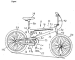
- the bicycle 10 in which an embodiment of the present invention is employed is a BMX-type bicycle provided with a frame 12 and a suspension assembly 14.
- the frame 12 primarily has a main frame member (an example of a first frame member) 16 and a rear frame member (an example of a second frame member) 18 elastically linked to the main frame member 16 via the suspension assembly 14.
- the bicycle 10 further comprises a rear wheel 19, which is mounted on the rear part of the frame 12 while allowed to rotate about a rear hub 19a; a front wheel 20, which is linked to the front part of the frame 12 while allowed to rotate about a front hub 20a; and a drive part 22 for propelling the bicycle.
- the drive part 22 has the same structure as in the past; that is, it comprises a bottom bracket 23 (Fig.
- crank 24 having a bottom bracket axle 23a, a right crank 24 equipped with a front sprocket 25 and nonrotatably mounted on the right end of the bottom bracket axle 23a, a left crank 26 nonrotatably mounted on the left end of the bottom bracket axle 23a, a rear sprocket 29 mounted on the rear hub 19a, and a drive chain 28 passed over the two sprockets 25 and 29.
- a pedal 27 is mounted on the tip of either crank 24 and 26.
- the main frame member 16 is composed of a plurality of rigid tubular members welded together. Specifically, the main frame member 16 has a seat tube 30, a head tube 32, an upper tube 33 for linking the two tubes 30 and 32, and a down tube 34.
- the main frame member 16 should preferably be manufactured using a rigid material such as a high-strength steel, chromium-molybdenum steel, aluminum alloy, titanium alloy, or other metal material; or a carbon composite or other such fiber-reinforced resin material.
- a seat post 38, with a saddle 37 mounted in the distal end thereof, is fixed to the seat tube 30 such that the vertical position thereof can be adjusted.
- a front fork 40 is rotatably mounted in the head tube 32.
- the front wheel 20 is rotatably mounted in the lower end of the front fork 40, and a steering handle assembly 42 is mounted on the upper end thereof such that the vertical position thereof can be adjusted.
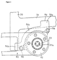
- a pair of brackets 50 for mounting the suspension assembly 14 are fixedly welded to the linkage portion of the down tube 34 and the seat tube 30.
- the brackets 50 have a first fixing part 50a, which is fixedly welded to the down tube 34; a second fixing part 50b, which is fixedly welded to the seat tube 30 diagonally underneath the first fixing part 50a; and a link 50c, which is bent into a quarter-circle segment and which links the two fixing parts 50a and 50b.
- brackets 50 allow the main frame member 16 to be reinforced by mounting the suspension assembly 14 and linking the down tube 34 and the seat tube 30.
- the main frame member 16 can be reinforced by linking the two tubes 34 and 30 with the aid of the suspension assembly 14 when the suspension assembly 14 is mounted separately on the tubes 34 and 30 without the use of the link 50c.
- the suspension assembly 14 is mounted between the two brackets 50 and is fixed with bolts 56.
- Each of the brackets 50 is provided with two bolt holes (not shown) for receiving the bolts 56 therethrough. The dismounting of the suspension assembly 14 or the rear frame member 18 is thus facilitated by the detachable mounting of the suspension assembly 14 on the main frame member 16 with the bolts 56.
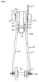
- the rear frame member 18 has a pair of substantially identical arm members 60, as shown in Fig. 4.
- Each arm member 60 has a circular suspension-mounting part 62 at the base end and a hub-mounting part 64 at the distal end.
- the suspension-mounting part 62 is fixed in the internal member (see below) of the suspension assembly 14.
- the rear hub 19a is mounted between the two hub-mounting parts 64, and a hub axle 19b is fixed in the hub-mounting parts 64.
- the suspension-mounting parts 62 have central holes 70 for accommodating the bottom bracket 23, and five bolt holes 72 for mounting bolts 74 are provided around each central hole 70.
- the bolts 74 are used to fix the suspension-mounting parts 62 to the internal member of the suspension assembly 14.
- the hub-mounting parts 64 are provided with slits 76 that extend in the longitudinal direction of the arm members 60, and the hub axle 19b of the rear hub 19a is fixed in these slits 76 by a known method.
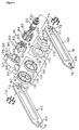
- the suspension assembly 14 comprises an external member (first member) 80 fixed to the main frame member 16; an internal member (second member) 82 disposed around the inside of the external member 80 and fixed to the rear frame member 18; first and second elastic members 83 and 84, which are expanded and contracted by the relative rotation of the external member 80 and internal member 82; and a link mechanism 86 for concentrically positioning the external member 80 and internal member 82 and linking the two members 80 and 82 in a relatively rotatable and axially immovable fashion.
- the external member 80 is a substantially cylindrical member that is made of metal and that has in its interior a circular opening 90 centered around a central axis extending to the right and left of the bicycle 10.
- Aluminum alloys, titanium alloys, chromium-molybdenum steel, high-strength steel, stainless-steel alloys, and the like are preferred as the metals for use in these.
- the internal member 82 can be accommodated together with the bottom bracket 23 and the two elastic members 83 and 84 in the opening 90.
- the opening 90 is formed such that its central axis coincides with the central axis of the bottom bracket 23 (axial center of the bottom bracket axle 23), and it is provided with five first protrusions 92 extending radially inward. As shown in Fig.
- circularly beveled first retaining parts 92a are provided along the border between the outer circumferential surface of the external member 80 and the circumferential side of the base ends (roots) of the first protrusions 92.
- the angular portions 83a around the outside of the first elastic members 83 are kept in contact by these first retaining parts 92a.
- each mounting part 94 extending radially outward is provided around the outside of the external member 80.
- the distal ends of each mounting part 94 are provided with screw holes 96 extending to a prescribed depth from both ends. These screw holes 96 are formed at positions that face the bolt holes of the brackets 50, and the suspension assembly 14 is mounted on the main frame member 16 by screwing the bolts 56 passing through the bolt holes of the brackets 50 into these screw holes 96.
- the base end of each mounting part 94 is provided with notches 97 cut out at both ends, and circular surfaces 98 are formed on the outer circumferential surfaces at the two ends of the external member 80.
- the internal member 82 is a substantially cylindrical member made of metal and provided with a through hole 104 for the internal mounting of the bottom bracket 23 by a mounting technique based on the use of known screws.
- Aluminum alloys, titanium alloys, chromium-molybdenum steel, high-strength steel, stainless-steel alloys, and the like are preferred as the metals for use in these.
- Five second protrusions 102 extending radially outward are formed on the outer circumferential part of the internal member 82. The second protrusions 102 are disposed alternately with the first protrusions 92.
- first elastic members 83 are mounted in the wider spaces
- second elastic members 84 are mounted in the narrower spaces.
- Circularly beveled second retaining parts 102a are provided along the border between the outer circumferential surface of the internal member 82 and the circumferential side of the base ends of the second protrusions 102.
- the angular portions 83b around the inside of the first elastic members 83 are kept in contact with these second retaining parts 102a.
- the other circumferential surfaces 92b of the first protrusions 92 and the other circumferential surfaces 102b of the second protrusions 102 face each other in a substantially parallel fashion in a state in which the two elastic members 83 and 84 are mounted.
- Screw holes 106 for screwing in the bolts 74 are formed on the tip side of the second protrusions 102.
- the rear frame member 18 is fixed to the suspension assembly 14 and elastically linked to the main frame member 16 by screwing the bolts 74 into these screw holes 106 through the bolt holes 72 of the arm members 60.
- the first elastic members 83 are members manufactured from bar-shaped elastic bodies and provided with a deformed rectangular shape in cross section. Urethane rubber, nitrile rubber, polyethylene elastomer, or the like can be used for such elastic bodies.
- the angular portions 83a on the outer circumferential side in contact with the first protrusions 92 are rounded in the form of acute angles, as are the angular portions 83b on the inner circumferential side in contact with the second protrusions 102.
- the first elastic members 83 are mounted while pressure is applied to one of the spaces formed by the first protrusions 92 and second protrusions 102, and both ends thereof are brought into contact with a second bushing 112.
- the angular portions 83a are held by the first retaining parts 92a around the outside in areas of contact with the first protrusions 92, whereas the angular portions 83b are held by the second retaining parts 102a, which are disposed along the inner circumference diagonally from the first retaining parts 92a, in areas of contact with the second protrusions 102.
- the first elastic members 83 are thus held by the corresponding diagonally arranged retaining parts 92a and 102a, thus making it more difficult for the first elastic members 83 to slip in a manner other than that involving expansion in the thickness direction (direction that intersects the direction of contraction) as a result of a contraction occurring when the first elastic members 83 are compressed and deformed.
- the shock absorption performance can therefore be stabilized.
- the first elastic members 83 are mounted in a secured state in one of the spaces while gaps 108a are formed near the inner circumferential surface of the external member 80. These gaps gradually become narrower in the clockwise direction away from the area of contact with the second protrusions 102. With such mounting, gaps 108b are also formed near the outer circumferential surface of the internal member 82. These gaps gradually become narrower in the counterclockwise direction away from the area of contact with the first protrusions 92.
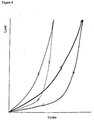
- the first elastic members 83 are disposed such that the gradually narrowing gaps 108a and 108b are formed, the first elastic members 83, when gradually sandwiched and contracted between the protrusions 92a and 102a, can swell in the direction that intersects the contraction direction, making it possible to increase the amount of rotation for the members 80 and 82 and to ensure adequate shock absorption.
- the first elastic members 83 When the internal member 82 performs relative rotation, and the first elastic members 83 first contract and then expand into the gaps 108a and 108b, the first elastic members 83 gradually adhere to the inner circumferential surface of the external member 80 and to the outer circumferential surface of the internal member 82, lowering the amount of slippage in the area where adhesion-induced friction occurs, reducing the likelihood that the first elastic members 83 will be worn down, and making it possible to inhibit wear-induced variations in the shock absorption performance.
- the second elastic members 84 are made of substantially plate-shaped elastic bodies mounted for the purpose of applying pressure to the first elastic members and inhibiting the collision noise resulting from contact between the two protrusions 92 and 102.
- Urethane rubber, nitrile rubber, polyethylene elastomer, and the like are preferred for use in such elastic bodies.
- the other circumferential surfaces 92b of the first protrusions 92 and the other circumferential surfaces 102b of the second protrusions 102 face each other in a substantially parallel fashion in a state in which pressure is exerted by the second elastic members 84 on the first elastic members 83.
- the gaps between the other circumferential surfaces 92b of the first protrusions 92 and the other circumferential surfaces 102b of the second protrusions 102 remain unchanged, and the pressure applied to the first elastic members 83 is less likely to vary when the second elastic members 84 slip in the radial direction.
- applying pressure to the first elastic members 83 suppresses the movement of the suspension assembly 14 under the weight of the rider when the latter mounts the bicycle.
- the link mechanism 86 has a first bushing 110 made of a synthetic resin and fixed to the external member 80, and a second bushing 112 made of metal, disposed around the outside of the first bushing 110, and fixed to the internal member 82.
- Polyacetal resins, nylon, Teflon (registered trade name), and other synthetic resins are preferred for use as the synthetic resins for the first bushing 110.
- Iron-based metals, copper, brass-based alloys, and other metals are preferred for use as the metals for the second bushing 112.
- the first bushing 110 is a flanged annular member having a first cylindrical part 114 in contact with the circular surfaces 98 of the external member 80 and a first annular part 116 folded away from the first cylindrical part 114 and kept in contact with the end face of the external member 80.
- the first bushing 110 is fixed by being fitted over the circular surfaces 98 of the external member 80.
- the second bushing 112 is a flanged annular member having a second cylindrical part 118 in contact with the first cylindrical part 114 of the first bushing 110 and a second annular part 120 folded away from the second cylindrical part 118 and kept in contact with the first annular part 116 of the first bushing 110.
- Five bolt holes 122 are formed in the second annular part 120 at positions facing the five bolt holes 72.
- the second bushing 112 is fixed by the bolts 74 to the internal member 82 together with the rear frame member 18.
- the gaps 108a and 108b between the first elastic members 83 and the external member 80 (and internal member 82) gradually become narrower, and if such compression continues until the gaps disappear (as shown in Fig. 7), the entire contact surface restricts the movement of the first elastic members 83, completing the stroke.
- the external and internal members had cylindrical shapes in the described embodiments, the shape of these two members is not limited to a cylindrical shape and includes rectangular columnar shapes and the like.
- the first elastic members in the above embodiments were configured from bar-shaped members provided with a deformed rectangular shape in cross section, the shape of the first elastic members is not limited to the aforementioned shape alone.
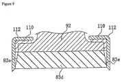
- a first elastic member 83d with a longitudinal cross section that is trapezoid in shape, to form along the two ends 83e of the first elastic member 83d gaps that become wider in the direction radially outward, and to allow the first elastic member 83d to gradually adhere to the annular parts of second bushings 112.
- the expansion space for the first elastic member 83d can be further expanded, the shock absorption capabilities improved, friction-induced slippage additionally reduced, and wear-induced variations in the shock absorption performance further inhibited.
- the arm members in the above embodiments were configured such that the hub axle of the rear wheel was chain-driven and supported at both ends, it is also possible for the rear wheel to be shaft-driven by a bevel-gear shaft, and the hub axle of the rear wheel to be supported on one side.
- the external member in the described embodiments were fixed to the main frame member, and the internal member was fixed to the rear frame member, the manner in which the internal and external members are fixed to the frame is not limited to the above and may include arrangements in which the rear frame member is fixed to the external member, and the main frame member to the internal member.
Landscapes
- Engineering & Computer Science (AREA)
- Mechanical Engineering (AREA)
- General Engineering & Computer Science (AREA)
- Physics & Mathematics (AREA)
- Acoustics & Sound (AREA)
- Aviation & Aerospace Engineering (AREA)
- Vibration Dampers (AREA)
- Axle Suspensions And Sidecars For Cycles (AREA)
- Vibration Prevention Devices (AREA)
Applications Claiming Priority (2)
| Application Number | Priority Date | Filing Date | Title |
|---|---|---|---|
| JP8712298 | 1998-03-31 | ||
| JP10087122A JP2977524B2 (ja) | 1998-03-31 | 1998-03-31 | 自転車用緩衝装置 |
Publications (2)
| Publication Number | Publication Date |
|---|---|
| EP0947418A2 true EP0947418A2 (de) | 1999-10-06 |
| EP0947418A3 EP0947418A3 (de) | 2000-09-27 |
Family
ID=13906163
Family Applications (1)
| Application Number | Title | Priority Date | Filing Date |
|---|---|---|---|
| EP99302534A Withdrawn EP0947418A3 (de) | 1998-03-31 | 1999-03-31 | Stossdämpfungsvorrichtung für Fahrrad |
Country Status (5)
| Country | Link |
|---|---|
| US (1) | US6481700B1 (de) |
| EP (1) | EP0947418A3 (de) |
| JP (1) | JP2977524B2 (de) |
| CN (1) | CN1082917C (de) |
| TW (1) | TW422793B (de) |
Cited By (2)
| Publication number | Priority date | Publication date | Assignee | Title |
|---|---|---|---|---|
| WO2007102996A3 (en) * | 2006-03-09 | 2007-11-15 | Gates Corp | Decoupling vibration isolator |
| EP3025948A1 (de) * | 2014-11-28 | 2016-06-01 | Jörn GmbH | Fahrradrahmen mit einer hinterbaufederung |
Families Citing this family (11)
| Publication number | Priority date | Publication date | Assignee | Title |
|---|---|---|---|---|
| US6880846B2 (en) * | 1998-03-27 | 2005-04-19 | Carl W. Schonfeld | Bicycle with shock absorber |
| JP4571341B2 (ja) * | 2001-06-18 | 2010-10-27 | 水島プレス工業株式会社 | ステアリング装置のダンパ機構 |
| US7345364B2 (en) * | 2004-02-04 | 2008-03-18 | Agere Systems Inc. | Structure and method for improved heat conduction for semiconductor devices |
| US20060064223A1 (en) * | 2004-09-20 | 2006-03-23 | Darrell Voss | Vehicle systems and method |
| US7222870B2 (en) | 2004-11-24 | 2007-05-29 | Shimano Inc. | Bicycle suspension assembly |
| US7093698B1 (en) * | 2005-05-25 | 2006-08-22 | Kun-Tien Chen | Shock-absorbing device for a motorcycle |
| JP4283858B2 (ja) * | 2007-03-29 | 2009-06-24 | 東海ゴム工業株式会社 | 防振マウント組立体 |
| KR100938592B1 (ko) | 2009-07-09 | 2010-01-26 | 정승식 | 완충 장치 및 이를 포함하는 자전거 |
| JP6955241B2 (ja) * | 2016-07-08 | 2021-10-27 | ▲浜▼元 陽一郎 | 回転伝達機構及びそれを備えた自転車 |
| CN106741499A (zh) * | 2016-12-06 | 2017-05-31 | 楼蕾 | 一种自行车减震组件及其自行车 |
| US20190162287A1 (en) * | 2017-11-28 | 2019-05-30 | Yoichiro Hamamoto | Rotation transmission mechanism, bicycle provided with rotation transmission mechanism, and elastically-deformable body used in rotation transmission mechanism |
Citations (1)
| Publication number | Priority date | Publication date | Assignee | Title |
|---|---|---|---|---|
| JPH09290790A (ja) | 1996-04-25 | 1997-11-11 | Miyata Ind Co Ltd | 自転車用フレーム |
Family Cites Families (20)
| Publication number | Priority date | Publication date | Assignee | Title |
|---|---|---|---|---|
| US2729465A (en) * | 1951-11-17 | 1956-01-03 | Torre Pier Luigi | Springing system for a motorcycle wheel |
| US3314512A (en) * | 1965-07-02 | 1967-04-18 | Borg Warner | Coupling device employing flexible hub assembly |
| US3788151A (en) * | 1972-10-06 | 1974-01-29 | Chrysler Corp | Shock absorbing starter clutch mechanism |
| US4355990A (en) * | 1980-09-22 | 1982-10-26 | The Gates Rubber Company | Torsionally elastic power transmitting device |
| US4679811A (en) * | 1986-06-26 | 1987-07-14 | Shuler Jerry N | Bicycle rear suspension system |
| JPS6328883A (ja) | 1986-07-23 | 1988-02-06 | Canon Inc | プラズマ反応装置 |
| JPH0616986Y2 (ja) * | 1986-08-11 | 1994-05-02 | 本田技研工業株式会社 | エンジンの始動装置 |
| GB8914374D0 (en) * | 1989-06-22 | 1989-08-09 | Indespension Ltd | Suspension unit |
| JP2598853B2 (ja) * | 1992-03-13 | 1997-04-09 | 紘二 ▲吉▼岡 | 自転車前輪制御機構 |
| US5277450A (en) * | 1992-07-07 | 1994-01-11 | Henschen Curtiss W | Multiple stage torsion axle |
| CN2136797Y (zh) * | 1992-09-16 | 1993-06-23 | 向茂祥 | 自行车缓冲避震器 |
| DE4233596A1 (de) * | 1992-10-06 | 1994-04-07 | Richard Kapp | Hinterradfederung für Zweiradfahrzeuge |
| US5413368A (en) * | 1993-09-16 | 1995-05-09 | Cannondale Corporation | Bicycle with trailing arm wheel suspensions |
| JP3354239B2 (ja) | 1993-11-16 | 2002-12-09 | 本田技研工業株式会社 | エンジンの防振動力取出装置 |
| JP2558257Y2 (ja) * | 1993-12-21 | 1997-12-24 | 宮田工業株式会社 | 自転車用フレームのダンパー機構 |
| JP3023657B2 (ja) * | 1995-09-25 | 2000-03-21 | 本田技研工業株式会社 | 自動2輪車のリヤスイングアーム |
| DE19717624A1 (de) | 1996-05-17 | 1997-11-20 | Mitsuba Corp | Reduktionsgetriebe mit einem Stoßabsorbiermechanismus |
| US5971416A (en) * | 1996-08-05 | 1999-10-26 | Hsiung; Kao Fu | Bicycle shock absorbing arrangement |
| US5997022A (en) * | 1997-07-02 | 1999-12-07 | Shimano Inc. | Bicycle suspension assembly |
| US6099010A (en) * | 1997-10-28 | 2000-08-08 | Gt Bicycles, Inc. | Bicycle with crank assembly suspension system |
-
1998
- 1998-03-31 JP JP10087122A patent/JP2977524B2/ja not_active Expired - Fee Related
-
1999
- 1999-03-17 TW TW088104164A patent/TW422793B/zh not_active IP Right Cessation
- 1999-03-30 US US09/281,622 patent/US6481700B1/en not_active Expired - Fee Related
- 1999-03-30 CN CN99104540A patent/CN1082917C/zh not_active Expired - Fee Related
- 1999-03-31 EP EP99302534A patent/EP0947418A3/de not_active Withdrawn
Patent Citations (1)
| Publication number | Priority date | Publication date | Assignee | Title |
|---|---|---|---|---|
| JPH09290790A (ja) | 1996-04-25 | 1997-11-11 | Miyata Ind Co Ltd | 自転車用フレーム |
Cited By (2)
| Publication number | Priority date | Publication date | Assignee | Title |
|---|---|---|---|---|
| WO2007102996A3 (en) * | 2006-03-09 | 2007-11-15 | Gates Corp | Decoupling vibration isolator |
| EP3025948A1 (de) * | 2014-11-28 | 2016-06-01 | Jörn GmbH | Fahrradrahmen mit einer hinterbaufederung |
Also Published As
| Publication number | Publication date |
|---|---|
| EP0947418A3 (de) | 2000-09-27 |
| TW422793B (en) | 2001-02-21 |
| JPH11278350A (ja) | 1999-10-12 |
| JP2977524B2 (ja) | 1999-11-15 |
| US6481700B1 (en) | 2002-11-19 |
| CN1230501A (zh) | 1999-10-06 |
| CN1082917C (zh) | 2002-04-17 |
Similar Documents
| Publication | Publication Date | Title |
|---|---|---|
| US6488603B2 (en) | Freewheel for a bicycle | |
| US6149176A (en) | Bicycle shock absorber with multilayered shock absorbing members | |
| US6209858B1 (en) | Bicycle shock absorber linked together through first and second annular members | |
| US6382381B1 (en) | Bicycle hub assembly | |
| US7891688B2 (en) | Bicycle frame with articulating linkage mounting arrangement | |
| US6481700B1 (en) | Bicycle shock absorber with elastic members closely fitted between first and second rotating members | |
| JP3265264B2 (ja) | 自転車用サスペンション組立体 | |
| US6454363B1 (en) | Wheel hub assembly | |
| US8042823B2 (en) | Suspension bicycle seat post | |
| US20090056495A1 (en) | Bicycle handlebar assembly | |
| EP1780111B1 (de) | Tretkurbellager-Anordnung | |
| US20130087011A1 (en) | Bicycle crank arm | |
| US6149175A (en) | Bicycle suspension | |
| US7222870B2 (en) | Bicycle suspension assembly | |
| JP2968518B1 (ja) | 自転車用回転伝達機構 | |
| TW202532290A (zh) | 踏板總成 |
Legal Events
| Date | Code | Title | Description |
|---|---|---|---|
| PUAI | Public reference made under article 153(3) epc to a published international application that has entered the european phase |
Free format text: ORIGINAL CODE: 0009012 |
|
| 17P | Request for examination filed |
Effective date: 19990421 |
|
| AK | Designated contracting states |
Kind code of ref document: A2 Designated state(s): DE FR GB IE IT NL |
|
| AX | Request for extension of the european patent |
Free format text: AL;LT;LV;MK;RO;SI |
|
| PUAL | Search report despatched |
Free format text: ORIGINAL CODE: 0009013 |
|
| AK | Designated contracting states |
Kind code of ref document: A3 Designated state(s): AT BE CH CY DE DK ES FI FR GB GR IE IT LI LU MC NL PT SE |
|
| AX | Request for extension of the european patent |
Free format text: AL;LT;LV;MK;RO;SI |
|
| RIC1 | Information provided on ipc code assigned before grant |
Free format text: 7B 62K 25/04 A, 7B 62K 25/28 B, 7B 62K 25/30 B |
|
| AKX | Designation fees paid |
Free format text: DE FR GB IE IT NL |
|
| GRAP | Despatch of communication of intention to grant a patent |
Free format text: ORIGINAL CODE: EPIDOSNIGR1 |
|
| RAP1 | Party data changed (applicant data changed or rights of an application transferred) |
Owner name: SHIMANO INC. |
|
| STAA | Information on the status of an ep patent application or granted ep patent |
Free format text: STATUS: THE APPLICATION IS DEEMED TO BE WITHDRAWN |
|
| 18D | Application deemed to be withdrawn |
Effective date: 20061114 |