EP0946303B1 - Zerkleinerungsmaschine mit einem emulgator - Google Patents
Zerkleinerungsmaschine mit einem emulgator Download PDFInfo
- Publication number
- EP0946303B1 EP0946303B1 EP97954400A EP97954400A EP0946303B1 EP 0946303 B1 EP0946303 B1 EP 0946303B1 EP 97954400 A EP97954400 A EP 97954400A EP 97954400 A EP97954400 A EP 97954400A EP 0946303 B1 EP0946303 B1 EP 0946303B1
- Authority
- EP
- European Patent Office
- Prior art keywords
- grinding machine
- machine according
- milling
- rotor
- stator
- Prior art date
- Legal status (The legal status is an assumption and is not a legal conclusion. Google has not performed a legal analysis and makes no representation as to the accuracy of the status listed.)
- Expired - Lifetime
Links
- 239000003995 emulsifying agent Substances 0.000 title description 24
- 238000003801 milling Methods 0.000 claims description 17
- 239000000463 material Substances 0.000 claims description 14
- 230000001804 emulsifying effect Effects 0.000 claims description 9
- 235000013372 meat Nutrition 0.000 claims description 7
- 238000000227 grinding Methods 0.000 claims 19
- 241000282461 Canis lupus Species 0.000 description 20
- 241000283153 Cetacea Species 0.000 description 9
- 238000009963 fulling Methods 0.000 description 4
- 238000004945 emulsification Methods 0.000 description 3
- 239000007795 chemical reaction product Substances 0.000 description 2
- 230000000694 effects Effects 0.000 description 2
- 238000007789 sealing Methods 0.000 description 2
- 241001295925 Gegenes Species 0.000 description 1
- 238000010276 construction Methods 0.000 description 1
- 239000000047 product Substances 0.000 description 1
- 230000003068 static effect Effects 0.000 description 1
Images



Classifications
-
- B—PERFORMING OPERATIONS; TRANSPORTING
- B02—CRUSHING, PULVERISING, OR DISINTEGRATING; PREPARATORY TREATMENT OF GRAIN FOR MILLING
- B02C—CRUSHING, PULVERISING, OR DISINTEGRATING IN GENERAL; MILLING GRAIN
- B02C18/00—Disintegrating by knives or other cutting or tearing members which chop material into fragments
- B02C18/30—Mincing machines with perforated discs and feeding worms
- B02C18/301—Mincing machines with perforated discs and feeding worms with horizontal axis
- B02C18/304—Mincing machines with perforated discs and feeding worms with horizontal axis with several axially aligned knife-perforated disc units
-
- B—PERFORMING OPERATIONS; TRANSPORTING
- B02—CRUSHING, PULVERISING, OR DISINTEGRATING; PREPARATORY TREATMENT OF GRAIN FOR MILLING
- B02C—CRUSHING, PULVERISING, OR DISINTEGRATING IN GENERAL; MILLING GRAIN
- B02C18/00—Disintegrating by knives or other cutting or tearing members which chop material into fragments
- B02C18/30—Mincing machines with perforated discs and feeding worms
- B02C18/305—Details
-
- B—PERFORMING OPERATIONS; TRANSPORTING
- B02—CRUSHING, PULVERISING, OR DISINTEGRATING; PREPARATORY TREATMENT OF GRAIN FOR MILLING
- B02C—CRUSHING, PULVERISING, OR DISINTEGRATING IN GENERAL; MILLING GRAIN
- B02C18/00—Disintegrating by knives or other cutting or tearing members which chop material into fragments
- B02C18/30—Mincing machines with perforated discs and feeding worms
- B02C18/36—Knives or perforated discs
- B02C2018/367—Resiliently mounted knives or discs
Definitions
- the invention relates to a comminution machine, especially meat grinder, with an emulsifier, one in a shredding device housed in a housing for meat to be chopped or similar material to be cut, which is advantageous with at least one of one Shaft driven and a non-rotatable perforated disc assigned knife set, a device for feeding the material to be cut into the shredding device, a drive and an outlet for the shredded Well, the one attached to the case, provided the emulsifier housing emulsifier is.
- the emulsifier should ensure that the wolf good with separately added aggregates evenly mixed is emulsified and the interior of the emulsifier is mostly connected to a vacuum source and so the air contained in the emulsifying wolf material is withdrawn.
- the object of the invention is a comminution machine of the type described in compact, simple design with the emulsifier connect and train this so that the shredded Well evenly and well mixed from the Shredding machine is promoted.
- a rotationally symmetrical stator in the emulsifier housing is formed with a support body which with a inward-facing support surface one on a whale body one rotatably connected to the shaft and adapted to the stator Rotor-facing, outward-facing whale surface encased in such a way that between the support surface and the whale surface has a wedge-shaped one common axis of the rotor and the stator rotating coaxially Gap is formed, and that on the rotor a coaxial hub connected to the flex body is provided with which the rotor is mounted on the shaft is.
- the flex body has a hollow cone is trained and so an otherwise available Hollow cone space as part of the interior of the Emulsifier encloses.
- the Support body and / or the flex body one wall each have uniform wall thickness if you do it disregard any surfaces that are not smooth leaves.
- the Wolfgut emulsifies particularly well when the Gap space with respect to the common axis equilateral, facing away from the shredding device End faces of the rotor and the stator tapered, the best of which is the face base areas belonging to the supporting surface and the walking surface form the support body / flex body; to this The Wolfgut is subject to a constant up to the outlet increasing static pressure.
- the shredding device can be designed as a cutting device.
- a particularly preferred embodiment of the invention exists in that on the rotor one on the flex body subsequent coaxial hub is provided with which the rotor is mounted on the shaft, so that a separate Drive for the emulsifier is not needed.
- the hub is preferably indirectly on the shaft one axially on the shaft with the help of the clamping device slidable actuation for the knife sets arranged.
- the wave can therefore with its free Extend into the hollow cone space of the whale body, so they are there for more, not with the emulsifier related tasks can be used: for example, a tensioning device for the Cutting device can be attached.
- the Wolfgut emulsifies particularly well when the support surface of the stator and / or the flexing surface of the rotor with several adjacent, preferably groove-shaped, coaxial ring grooves are provided, each the entire support surface and / or fulling surface of ring grooves can be taken.
- the support surface of the stator and / or the milling surface of the rotor but also to each of them have parallel, preferably groove-shaped longitudinal grooves; usually it is best if ring grooves on the support surface with longitudinal grooves on the fulling surface be combined.
- the flow of the wolf good can be supported by the ring grooves of those running transversely to them parallel to the supporting surface or the flexing surface, preferably groove-shaped longitudinal grooves are crossed in the way that they have adjacent ring grooves with each other connect, with an unimpeded flow in turn is easily avoidable that the longitudinal grooves to each other are staggered so that the Wolfgut must constantly change its direction of flow.
- a particularly compact construction of the emulsifier is reached when the gap in one between each Pipe socket of the stator and the rotor, annulus connected to the outlet passes.
- the invention allows a very compact arrangement of the emulsifier on the wolf, but allowed at the same time, the emulsifier to be crushed and to adapt to emulsifying cutting or wolfing material and solely by changing the rotor and / or stator to produce very different products.
- a wolf according to the invention exists according to Fig.1 essentially from a housed in a wolf housing 1 Cutting device 2, one the material to be cut corresponding to the conveying direction F into the cutting device 2 transporting, omitted in the drawing Conveyor, one with the wolf housing 1 connected emulsifier housing 31 for an emulsifier 3 as well as a rotary, not visible in the drawing Drive for a shaft 4.
- the shaft 4 takes care of the Operation of the conveyor screw, for example Conveyor, the cutting device 2 and of the emulsifier 3.
- the cutting device 2 is in a known manner from rotatable, arranged in the Wolf housing 1 perforated disks 21 and associated knife sets 22 formed on the shaft 4, but are axially movable and of a suitable Clamping device 41 against the respective perforated disk 21 to be pulled.
- the wolf is easily changeable using a Holding device 5 can be fixed in a stationary housing 6, wherein the holding device 5 consists of several retractable, retaining bolts located in the wolf housing 1 51 and a suitable clamping connection 52.
- the drive and the conveyor can be housed.
- the emulsifier 3 consists in detail a stator 32 and a rotor 33.
- the stator 32 is part of the emulsifier housing 31 as well as a connecting flange 34 with which the emulsifier housing 31 easily detachably flanged to the wolf housing 1 is.
- the arrangement of the frustoconical support body 32a is made so that the associated cone angle a (Fig. 4,5) is open in the conveying direction F.
- the cover 35 there is an opening 35a through the interior of the stator 32 and the rotor 33 common 36 of the emulsifier 3 with a vacuum source connected and exposed in the flow direction S. is. via an outlet 32c in the pipe socket 32b however, the emulsified end product from the wolf in the transport direction T carried out, as well as the Delivery direction F and the flow direction S alone is illustrated by a direction arrow.
- the stator 32 surrounds one with its support body 32a hollow tapered flex body 33a of the rotor 33 and with his pipe socket 32b a similar one on the flex body 33a attaching (inner) pipe socket 33b of the rotor 33.
- Both the support body 32a and the flex body 33a point, from the different designs of their surfaces apart from that, a uniform wall thickness s (Fig. 2-5).
- the arrangement is such that the same (like the support body 32a) frustoconical shaped flex body 33a with an associated cone angle b (Fig. 2,3) is open in the conveying direction F, which is slightly larger than the cone angle a of the support body 32a, so that a circumferential between the two Gap 36a arises, which is towards the Pipe socket 32b, 33b continuously narrowed in the conveying direction F each terminate the stator 32 and the rotor 33.
- the rotor 33 is connected to the shaft 4 via a hub 33c rotatably connected to the flex body 33a on the Pipe socket 33b on the opposite side and a hollow cone space 36c of the flex body 33a against the Cutting device 2 completes.
- the axially movable Hub 33c is not directly on shaft 4 here stored, but instead on one on the shaft 4 guided and with the help of the clamping device 41 axially sliding actuator 42 for the knife sets 22. Es it is understood that the rotor 33 in a suitable manner is axially fixed, for example by means of the cover 35; the technical details are in the drawing omitted.
- the rotor 33 is also located on the inner one Then pipe socket 33b, a circumferential sealing collar 33d from individual lips (Fig. 2,3) that extend to the outer Pipe socket 32b is sufficient and prevents wolf material from the annular space 36b into the remaining interior 36 reached.
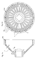
- FIG. 2 shows a rotor 33 with a flexing surface 33f shown on the to the gap space 36a facing side of the flex body 33a and with a variety of in the side view of the 2b pointing radially outwards from the axis of symmetry, in the longitudinal direction (Fig.2a) parallel to the Milled surface 33f extending near the hub 33c beginning longitudinal grooves L is provided, in which the Wolfgut in the gap space 36a continuously to the outside can flow; other, located between the longitudinal grooves L.
- Longitudinal grooves L '(Fig.2b) are somewhat shorter, so that the entire flexing surface 33f is penetrated by longitudinal grooves L, L ' is.
- the rotor 33 of FIG. 3 is included a completely smooth fulling surface 33f, and it other surface shapes can also be used; for example, it is conceivable that the fulling surface 33f is similar to one on the support body 32a on its side pointing towards the gap 36a located support surface 32d (Fig.4).
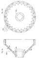
- 4,5 are examples of the Design of the support surface 32d reproduced.
- Execution 4 is with concentric, closely adjacent and groove-shaped ring grooves R on the Support surface 32d formed, which in particular in the 1 shown together with the longitudinal grooves L, L 'vigorous flexing and crushing of the wolf material cause.
- vertical longitudinal grooves L are provided be through which the wolf material from an annular groove R to radial can flow out to the next.
- the flex surface 33f can also here (Fig.5) the support surface 32d be completely smooth; it but are also others that promote whale work Surface shapes possible, such as spiral or helical grooves.
Landscapes
- Engineering & Computer Science (AREA)
- Food Science & Technology (AREA)
- Crushing And Pulverization Processes (AREA)
- Meat, Egg Or Seafood Products (AREA)
- Disintegrating Or Milling (AREA)
- Crushing And Grinding (AREA)
- Finish Polishing, Edge Sharpening, And Grinding By Specific Grinding Devices (AREA)
Description
- Fig. 1
- einen erfindungsgemäßen Wolf im Längsschnitt in der Gebrauchslage,
- Fig. 2
- in den Teilfiguren 2a,2b eine erste Ausführung eines Rotors im Längsschnitt der Gebrauchslage und in der zugehörigen Seitenansicht,
- Fig. 3
- in den Teilfiguren 3a,3b eine zweite Ausführung eines Rotors im Längsschnitt der Gebrauchslage und in der zugehörigen Seitenansicht,
- Fig. 4
- in den Teilfiguren 4a,4b eine erste Ausführung eines Stators einer gegen die Förderrichtung des Schneidgutes dargestellten Ansicht und einer der Gebrauchslage entsprechenden zugehörigen Seitenansicht und
- Fig. 5
- in den Teilfiguren 5a,5b in gleicher Darstellung eine zweite Ausführung eines Stators,
- 1
- Wolfgehäuse
- 2
- Zerkleinerungseinrichtung /Schneideinrichtung
- 21
- Lochscheibe
- 22
- Messersatz
- 3
- Emulqator
- 31
- Emulaatoraehäuse
- 32
- Stator
- 32a
- Stützkörper
- 32b
- (äußerer) Rohrstutzen
- 32c
- Auslaß
- 32d
- Stützfläche
- 33
- Rotor
- 33a
- Walkkörper
- 33b
- (innerer) Rohrstutzen
- 33c
- Nabe
- 33d
- Dichtbund
- 33e
- Durchgangsbohrung
- 33f
- Walkfläche
- 34
- Anschlußflansch
- 35
- Deckel
- 35a
- Öffnung
- 36
- Innenraum
- 36a
- Spaltraum
- 36b
- Ringraum
- 36c
- Hohlkegelraum
- 4
- Welle
- 41
- Spanneinrichtung
- 42
- Betätigung
- 5
- Haltevorrichtung
- 51
- Haltebolzen
- 52
- Spannverbindung
- 6
- Gehäuse
- a,b
- Kegelwinkel
- h
- Höhe
- s
- Wanddicke
- F
- Förderrichtung
- L,L',L"
- Längsnut
- R
- Ringnut
- S
- Strömungsrichtung
- T
- Transportrichtung
Claims (17)
- Zerkleinerungsmaschine, insbesondere Fleischwolf, mit einem Emulgator (3), einer in einem Gehäuse (1) untergebrachten Zerkleinerungseinrichtung (2) für zu zerkleinerndes Fleisch oder dergleichen Schneidgut, die vorteilhaft mit mindestens einem von einer Welle (4) angetriebenen und einer drehfesten Lochscheibe (21) zugeordneten Messersatz (22) versehen ist, einer Einrichtung zum Zuführen des Schneidgutes in die Zerkleinerungseinrichtung (2), einem Antrieb sowie einem Auslaß (32c) für das zerkleinerte Gut, die an einem mit dem Gehäuse (1) verbundenen, den Emulgator (3) umfassenden Emulgatorgehäuse (31) vorgesehen ist,
dadurch gekennzeichnet, daß
an dem Emulgatorgehäuse (31) ein rotationssymmetrischer Stator (32) mit einem Stützkörper (32a) ausgebildet ist, der mit einer nach innen weisenden Stützfläche (32d) eine an einem Walkkörper (33a) eines mit der Welle (4) drehverbundenen, dem Stator (32) angepaßten Rotors (33) befindliche, nach außen weisende Walkfläche (33f) in der Weise umhüllt, daß zwischen der Stützfläche (32d) und der Walkfläche (33f) ein keilförmig zulaufender, eine gemeinsame Achse des Rotors (33) und des Stators (32) koaxial umlaufender Spaltraum (36a) ausgebildet ist, und daß an dem Rotor (33) eine an den Walkkörper (33a) anschließende koaxiale Nabe (33c) vorgesehen ist, mit welcher der Rotor (33) auf der Welle (4) gelagert ist. - Zerkleinerungsmaschine nach Anspruch 1, dadurch gekennzeichnet, daß die Stützfläche (32d) und die Walkfläche (33f) jeweils kegelstumpfförmig ausgebildet sind.
- Zerkleinerungsmaschine nach Anspruch 1 und 2, dadurch gekennzeichnet, daß der Walkkörper (33a) hohlkegelig ausgebildet ist.
- Zerkleinerungsmaschine nach einem der Ansprüche 1 bis 3, dadurch gekennzeichnet, daß der Stützkörper (32a) und/oder der Walkkörper (33a) eine Wandung jeweils gleichmäßiger Wanddicke (s) aufweisen.
- Zerkleinerungsmaschine nach einem der Ansprüche 1 bis 3, dadurch gekennzeichnet, daß sich der Spaltraum (36a) zu den bezüglich der gemeinsamen Achse gleichseitigen, von der Schneideinrichtung (2) abgewandten Stirnflächen des Rotors (33) und des Stators (32) hin verjüngt.
- Zerkleinerungsmaschine nach einem der Ansprüche 3 bis 5, dadurch gekennzeichnet, daß die Stirnflächen jeweils die zu der Stützfläche (32d) und der Walkfläche (33f) gehörigen Grundflächen des hohlkegelförmigen Stützkörpers/Walkkörpers (32a/33a) bilden.
- Zerkleinerungsmaschine nach einem der Ansprüche 1 bis 5, dadurch gekennzeichnet, daß die Nabe (33c) mittelbar über eine auf der Welle (4) mit Hilfe der Spanneinrichtung (41) axial verschiebbare Betätigung (42) für die Messersätze (22) befestigt ist.
- Zerkleinerungsmaschine nach einem der Ansprüche 2 bis 7, dadurch gekennzeichnet, daß die Nabe (33c) an der durch den kleineren Durchmesser bestimmten Seite des Walkkörpers (33a) vorgesehen ist.
- Zerkleinerungsmaschine nach einem der Ansprüche 1 bis 8, dadurch gekennzeichnet, daß die Stützfläche (32d) des Stators (32) und/oder die Walkfläche (33f) des Rotors (33) mit mehreren einander benachbarten, vorzugsweise rillenförmigen, koaxialen Ringnuten (R) versehen sind.
- Zerkleinerungsmaschine nach Anspruch 9, dadurch gekennzeichnet, daß die gesamte Stützfläche (32d) und/oder Walkfläche (33f) von Ringnuten (R) eingenommen werden.
- Zerkleinerungsmaschine nach einem der Ansprüche 1 bis 10, dadurch gekennzeichnet, daß die Stützfläche (32d) des Stators (32) und/oder die Walkfläche (33f) des Rotors (33) zu ihnen jeweils parallele, vorzugsweise rillenförmige Längsnuten (L,L',L") aufweisen.
- Zerkleinerungsmaschine nach Anspruch 9 oder 10, dadurch gekennzeichnet, daß die Ringnuten (R) von zu ihnen quer verlaufenden, zu der Stützfläche (32d) oder der Walkfläche (33f) parallelen, vorzugsweise rillenförmigen Längsnuten (L") gekreuzt werden in der Weise, daß sie benachbarte Ringnuten (R) miteinander verbinden.
- Zerkleinerungsmaschine nach Anspruch 12, dadurch gekennzeichnet, daß die Längsnuten (L") zueinander versetzt angeordnet sind.
- Zerkleinerungsmaschine nach einem der Ansprüche 2 bis 13, dadurch gekennzeichnet, daß die Stützfläche (32d) und/oder die Walkfläche (33f) als glatte Kegelflächen ausgebildet sind.
- Zerkleinerungsmaschine nach einem der Ansprüche 1 bis 14, dadurch gekennzeichnet, daß der Spaltraum (36a) in einen zwischen je einem Rohrstutzen (32b) des Stators (32) und des Rotors (33) ausgebildeten, mit dem Auslaß (32c) verbundenen Ringraum (36b) übergeht.
- Zerkleinerungsmaschine nach Anspruch 15, dadurch gekennzeichnet, daß der Spaltraum (36a), vorzugsweise in der Nähe des Ringraumes (36b), durch mindestens eine Durchgangsbohrung (33e) in dem Walkkörper (33a) mit einer Unterdruckquelle strömungstechnisch verbunden ist.
- Zerkleinerungsmaschine nach einem der Ansprüche 1 bis 15, dadurch gekennzeichnet, daß der auf die Welle (4) wirkende Antrieb für die Schneideinrichtung (2), die Fördereinrichtung und den Emulgator (3) vorgesehen ist.
Applications Claiming Priority (3)
| Application Number | Priority Date | Filing Date | Title |
|---|---|---|---|
| DE29622298U | 1996-12-21 | ||
| DE29622298U DE29622298U1 (de) | 1996-12-21 | 1996-12-21 | Fleischwolf |
| PCT/EP1997/007020 WO1998028077A1 (de) | 1996-12-21 | 1997-12-13 | Zerkleinerungsmaschine mit einem emulgator |
Publications (2)
| Publication Number | Publication Date |
|---|---|
| EP0946303A1 EP0946303A1 (de) | 1999-10-06 |
| EP0946303B1 true EP0946303B1 (de) | 2001-04-11 |
Family
ID=8033706
Family Applications (1)
| Application Number | Title | Priority Date | Filing Date |
|---|---|---|---|
| EP97954400A Expired - Lifetime EP0946303B1 (de) | 1996-12-21 | 1997-12-13 | Zerkleinerungsmaschine mit einem emulgator |
Country Status (7)
| Country | Link |
|---|---|
| US (1) | US6402069B1 (de) |
| EP (1) | EP0946303B1 (de) |
| JP (1) | JP3258033B2 (de) |
| BR (1) | BR9713603A (de) |
| DE (2) | DE29622298U1 (de) |
| DK (1) | DK0946303T3 (de) |
| WO (4) | WO1998028078A1 (de) |
Families Citing this family (15)
| Publication number | Priority date | Publication date | Assignee | Title |
|---|---|---|---|---|
| DE29809485U1 (de) | 1998-05-28 | 1998-09-10 | Tiromat Krämer + Grebe GmbH & Co. KG, 35216 Biedenkopf | Wolf zum Zerkleinern von Gefrier- und Frischfleisch |
| DE29819180U1 (de) * | 1998-10-28 | 1999-07-08 | Tiromat Krämer + Grebe GmbH & Co. KG, 35216 Biedenkopf | Fleischverarbeitungsmaschine mit einer Evakuierungseinrichtung |
| DE29911090U1 (de) | 1999-06-25 | 1999-10-07 | Tiromat Krämer + Grebe GmbH & Co. KG, 35216 Biedenkopf | Maschine zum Zerkleinern von organischem Schnittgut |
| WO2001007165A1 (fr) * | 1999-07-26 | 2001-02-01 | Eduard Fedorovich Syrovatsky | Procede de traitement de viande, hachoir a viande, unite de coupe du hachoir a viande (2 mode de realisation), separateur de viande et paire de coupe du hachoir a viande |
| DE19960409A1 (de) * | 1999-12-15 | 2001-06-21 | Inotec Gmbh Maschinenentwicklu | Vorrichtung zum Zerkleinern eines Zerkleinerungsgutes |
| RU2220771C1 (ru) * | 2002-07-04 | 2004-01-10 | Серебряков Владимир Михайлович | Нож лопастной |
| RU2297324C2 (ru) * | 2004-11-24 | 2007-04-20 | Игорь Феликсович Шлегель | Устройство для измельчения и перемешивания пластичных материалов, преимущественно глины |
| AT503389B1 (de) * | 2006-03-24 | 2008-03-15 | Laska Maschf Gmbh | Fleischwolf |
| SE530009C2 (sv) * | 2006-06-01 | 2008-02-05 | Metso Paper Inc | Anordning för uppriktning av en malapparats maldon |
| RU2384401C1 (ru) * | 2008-11-06 | 2010-03-20 | Игорь Феликсович Шлегель | Устройство для измельчения и перемешивания пластичных материалов, преимущественно глины |
| RU2411122C1 (ru) * | 2009-11-23 | 2011-02-10 | Игорь Феликсович Шлегель | Устройство для измельчения и перемешивания пластичных материалов, преимущественно глины |
| RU2435664C1 (ru) * | 2010-03-15 | 2011-12-10 | Игорь Феликсович Шлегель | Устройство для измельчения пластичных материалов |
| DE102010044630A1 (de) * | 2010-09-06 | 2012-03-08 | Stephan Machinery Gmbh | Verfahren und Vorrichtung zur Herstellung von pürierter Nahrung |
| DE202014105123U1 (de) * | 2014-10-27 | 2016-01-28 | Mirko Winter | Vorrichtung zur Zerkleinerung von Faserverbundwerkstoffen |
| CN118122199B (zh) * | 2024-05-08 | 2024-07-26 | 山西雅美德印刷科技有限公司 | 一种印刷油墨加工用混匀调色设备 |
Family Cites Families (26)
| Publication number | Priority date | Publication date | Assignee | Title |
|---|---|---|---|---|
| US930920A (en) * | 1907-09-05 | 1909-08-10 | A J Deer Co | Meat-cutter. |
| DE484514C (de) * | 1928-09-08 | 1929-10-21 | Alexanderwerk A Von Der Nahmer | Zerkleinerungsmaschine mit Vorschubschnecke und Messerwerk |
| US2200786A (en) * | 1938-11-15 | 1940-05-14 | Ardrey Otis Roy | Meat grinder |
| CH247700A (de) * | 1944-10-25 | 1947-03-31 | Peter Jorgensen Martin Michael | Fleischwolf. |
| FR1157041A (fr) * | 1956-07-30 | 1958-05-23 | Societe D'etudes, - Construction Et Diffusion De Materiel D'alimentation | Perfectionnements aux machines à hacher |
| US2963232A (en) * | 1956-11-28 | 1960-12-06 | Eric S Smith | Grinder |
| GB869409A (en) * | 1960-03-21 | 1961-05-31 | Pavia Charles | Auxiliary comminutor |
| CH408688A (de) * | 1963-12-10 | 1966-02-28 | Carl Schnell Maschinenfabrik | Zerkleinerungsmaschine für landwirtschaftliche Erzeugnisse, insbesondere Fleisch |
| US3305183A (en) * | 1964-06-15 | 1967-02-21 | Morden Machines Company | Machine for treating pulp material |
| AT320464B (de) * | 1968-03-01 | 1975-02-10 | Vemag Verdener Masch App | Fleischzerkleinerungsmaschine mit mindestens einer Lochscheibe, vor der ein mehrarmiger Messerkopf umläuft |
| DE2152718C3 (de) * | 1970-10-23 | 1979-10-11 | Mitsubishi Petrochemical Co., Ltd., Tokio | Vorrichtung zum Verarbeiten von thermoplastischen Kunststoff enthaltendem Kunststoffabfall |
| GB1405013A (en) * | 1972-02-10 | 1975-09-03 | Winn Coales Denso Ltd | Mixing mechanisms |
| DE2310321B1 (de) * | 1973-03-01 | 1974-01-31 | Int Laboratoriums App Gmbh | Emulgier- und dispergiervorrichtung mit rotierenden konzentrischen werkzeugkraenzen |
| US4003521A (en) * | 1975-05-27 | 1977-01-18 | Speco, Inc. | Dual-phase meat grinder adapter |
| DE2827369A1 (de) * | 1978-06-22 | 1980-01-03 | Karl Schnell | Zerkleinerungsmaschine mit wenigstens einem rotierenden zerkleinerungswerkzeug |
| DE2901112A1 (de) * | 1979-01-12 | 1980-07-24 | Dueker Eisenwerk | Schneidemaschine, insbesondere fleischwolf |
| DK160123C (da) * | 1981-05-20 | 1991-07-08 | Wolfking Danmark As | Fremgangsmaade til findeling af faste, spiselige materialer og emulgering af i materialet indeholdte eller tilsatte stoffer. |
| DK158285C (da) * | 1983-05-24 | 1990-11-12 | Knud Simonsen | Maskine til finhakning af koedvarer. |
| DE3620598C2 (de) * | 1986-06-19 | 1997-08-14 | Schnell Maschfab Karl | Vorrichtung zum automatischen Verstellen des Schneidsatzes einer Fleischzerkleinerungsmaschine |
| SE459186B (sv) * | 1986-08-07 | 1989-06-12 | Sunds Defibrator | Anordning foer behandling av fibersuspensioner genom silning och mekanisk bearbetning |
| US4844372A (en) * | 1988-07-11 | 1989-07-04 | Weiler And Company, Inc | Double plate retrofit assembly for a meat grinder |
| SU1738350A1 (ru) * | 1989-08-29 | 1992-06-07 | Н.П. Мартынюк, Е.Н. Мартынюк, С.Н. Мартынюк и Л.Ф. Мартынюк | Устройство дл измельчени |
| DE4421711C2 (de) * | 1994-06-21 | 1997-12-11 | Thueringer Fleischereimaschine | Vorrichtung zum Zerkleinern von organischen Massen |
| DE4437144B4 (de) * | 1994-10-18 | 2006-04-13 | Wolfgang Greiner | Messersatz für einen Fleischwolf und Klingeneinsatz für einen solchen |
| DE29512820U1 (de) * | 1995-08-09 | 1995-10-12 | Tetra Laval Convenience Food GmbH & Co. KG, 35216 Biedenkopf | Zerkleinerungsmaschine |
| DE29601686U1 (de) * | 1996-02-01 | 1996-03-21 | Krüger, Günter, 99310 Dornheim | Vorrichtung zum Emulgieren von zerkleinerten organischen Massen, Stoffen und/oder Flüssigkeiten |
-
1996
- 1996-12-21 DE DE29622298U patent/DE29622298U1/de not_active Expired - Lifetime
-
1997
- 1997-12-13 WO PCT/EP1997/007022 patent/WO1998028078A1/de not_active Ceased
- 1997-12-13 WO PCT/EP1997/007017 patent/WO1998028076A1/de not_active Ceased
- 1997-12-13 DK DK97954400T patent/DK0946303T3/da active
- 1997-12-13 DE DE59703367T patent/DE59703367D1/de not_active Expired - Fee Related
- 1997-12-13 WO PCT/EP1997/007021 patent/WO1998028079A1/de not_active Ceased
- 1997-12-13 WO PCT/EP1997/007020 patent/WO1998028077A1/de not_active Ceased
- 1997-12-13 EP EP97954400A patent/EP0946303B1/de not_active Expired - Lifetime
- 1997-12-13 US US09/331,558 patent/US6402069B1/en not_active Expired - Fee Related
- 1997-12-13 JP JP52832998A patent/JP3258033B2/ja not_active Expired - Fee Related
- 1997-12-13 BR BR9713603-4A patent/BR9713603A/pt not_active IP Right Cessation
Also Published As
| Publication number | Publication date |
|---|---|
| US6402069B1 (en) | 2002-06-11 |
| DK0946303T3 (da) | 2001-08-13 |
| BR9713603A (pt) | 2000-04-04 |
| WO1998028079A1 (de) | 1998-07-02 |
| DE29622298U1 (de) | 1998-04-16 |
| JP3258033B2 (ja) | 2002-02-18 |
| DE59703367D1 (de) | 2001-05-17 |
| WO1998028076A1 (de) | 1998-07-02 |
| EP0946303A1 (de) | 1999-10-06 |
| WO1998028077A1 (de) | 1998-07-02 |
| WO1998028078A1 (de) | 1998-07-02 |
| JP2000513652A (ja) | 2000-10-17 |
Similar Documents
| Publication | Publication Date | Title |
|---|---|---|
| EP0946303A1 (de) | Zerkleinerungsmaschine mit einem emulgator | |
| EP1825907B1 (de) | Homogenisator ("Co-Twister") | |
| DE1300426B (de) | Vorrichtung zum Homogenisieren eines hochviskosen Gemisches | |
| EP2987557B1 (de) | Zerkleinerungsmaschine zur zerkleinerung eines produkts | |
| EP0813908B1 (de) | Schneid- und/oder Lagersysteme für Lebensmittel-Zerkleinerungsmaschinen, die nach dem Wolfprinzip arbeiten | |
| EP0376001B1 (de) | Rührwerksmühle mit Trennvorrichtung in einem rotierenden Käfig | |
| DE2931276C2 (de) | ||
| DE2517131C2 (de) | Vorrichtung zum Auflockern von feuchten, faserhaltigen Materialien | |
| DE102008049339B4 (de) | Vorrichtung zum Bearbeiten von Aufgabegut | |
| DE3844380C1 (en) | Agitator mill with separating device in a rotating cage | |
| DE3837740A1 (de) | Vorrichtung zur zerkleinerung bzw. zum mahlen von faserstoffmaterial, vorzugsweise hackschnitzeln | |
| DE19720959A1 (de) | Rotor-Stator-Maschine | |
| DE3837757C2 (de) | ||
| DE4213608C2 (de) | Vorrichtung zum Zerkleinern von Gummibrocken | |
| DE19652904A1 (de) | Messermühle zur Zerkleinerung von Kunststoffmaterial | |
| DE102005029899A1 (de) | Messerschneidmühle | |
| DE1461012C3 (de) | Vonchtung zum Zerfasern von Papierstoff | |
| DE19948493C2 (de) | Förder-, Pump- und Schneidsystem für Lebensmittelzerkleinerungsmaschinen, insbesondere für Fleischwölfe | |
| DE69931002T2 (de) | Vorrichtung zum Zerkleinern von synthetischen oder natürlichen organischen Materialien, wie z.B. Holz | |
| DE3837766C2 (de) | ||
| EP0740953B1 (de) | Vorrichtung zum Mahlen und Mischen von Massen | |
| DE1217754B (de) | Muehle | |
| DE3444912C2 (de) | Vorrichtung zum Behandeln pumpfähiger Materialien | |
| EP1606055B1 (de) | Einrichtung zum trennen und abfördern von rohstoffen | |
| DE3630742C2 (de) |
Legal Events
| Date | Code | Title | Description |
|---|---|---|---|
| PUAI | Public reference made under article 153(3) epc to a published international application that has entered the european phase |
Free format text: ORIGINAL CODE: 0009012 |
|
| 17P | Request for examination filed |
Effective date: 19990511 |
|
| AK | Designated contracting states |
Kind code of ref document: A1 Designated state(s): DE DK |
|
| 17Q | First examination report despatched |
Effective date: 19991104 |
|
| GRAG | Despatch of communication of intention to grant |
Free format text: ORIGINAL CODE: EPIDOS AGRA |
|
| GRAG | Despatch of communication of intention to grant |
Free format text: ORIGINAL CODE: EPIDOS AGRA |
|
| GRAH | Despatch of communication of intention to grant a patent |
Free format text: ORIGINAL CODE: EPIDOS IGRA |
|
| GRAH | Despatch of communication of intention to grant a patent |
Free format text: ORIGINAL CODE: EPIDOS IGRA |
|
| GRAA | (expected) grant |
Free format text: ORIGINAL CODE: 0009210 |
|
| AK | Designated contracting states |
Kind code of ref document: B1 Designated state(s): DE DK |
|
| REF | Corresponds to: |
Ref document number: 59703367 Country of ref document: DE Date of ref document: 20010517 |
|
| RAP2 | Party data changed (patent owner data changed or rights of a patent transferred) |
Owner name: CONVENIENCE FOOD SYSTEMS WALLAU GMBH & CO. KG |
|
| REG | Reference to a national code |
Ref country code: DK Ref legal event code: T3 |
|
| PLBE | No opposition filed within time limit |
Free format text: ORIGINAL CODE: 0009261 |
|
| STAA | Information on the status of an ep patent application or granted ep patent |
Free format text: STATUS: NO OPPOSITION FILED WITHIN TIME LIMIT |
|
| 26N | No opposition filed | ||
| PGFP | Annual fee paid to national office [announced via postgrant information from national office to epo] |
Ref country code: DK Payment date: 20051223 Year of fee payment: 9 |
|
| PGFP | Annual fee paid to national office [announced via postgrant information from national office to epo] |
Ref country code: DE Payment date: 20061231 Year of fee payment: 10 |
|
| REG | Reference to a national code |
Ref country code: DK Ref legal event code: EBP |
|
| PG25 | Lapsed in a contracting state [announced via postgrant information from national office to epo] |
Ref country code: DK Free format text: LAPSE BECAUSE OF NON-PAYMENT OF DUE FEES Effective date: 20070102 |
|
| PG25 | Lapsed in a contracting state [announced via postgrant information from national office to epo] |
Ref country code: DE Free format text: LAPSE BECAUSE OF NON-PAYMENT OF DUE FEES Effective date: 20080701 |