EP0945713A1 - Durchflussreguliergerät für Flüssigkeiten - Google Patents
Durchflussreguliergerät für Flüssigkeiten Download PDFInfo
- Publication number
- EP0945713A1 EP0945713A1 EP99105014A EP99105014A EP0945713A1 EP 0945713 A1 EP0945713 A1 EP 0945713A1 EP 99105014 A EP99105014 A EP 99105014A EP 99105014 A EP99105014 A EP 99105014A EP 0945713 A1 EP0945713 A1 EP 0945713A1
- Authority
- EP
- European Patent Office
- Prior art keywords
- yoke
- bypass line
- valves
- channel
- plungers
- Prior art date
- Legal status (The legal status is an assumption and is not a legal conclusion. Google has not performed a legal analysis and makes no representation as to the accuracy of the status listed.)
- Granted
Links
- 239000007788 liquid Substances 0.000 title claims description 5
- 230000001105 regulatory effect Effects 0.000 claims description 8
- 238000007789 sealing Methods 0.000 claims description 2
- 239000011521 glass Substances 0.000 description 4
- 210000003811 finger Anatomy 0.000 description 2
- 238000005259 measurement Methods 0.000 description 2
- 210000003813 thumb Anatomy 0.000 description 2
- XLYOFNOQVPJJNP-UHFFFAOYSA-N water Substances O XLYOFNOQVPJJNP-UHFFFAOYSA-N 0.000 description 2
- 230000006835 compression Effects 0.000 description 1
- 238000007906 compression Methods 0.000 description 1
- 230000002950 deficient Effects 0.000 description 1
- 238000010438 heat treatment Methods 0.000 description 1
Images
Classifications
-
- G—PHYSICS
- G01—MEASURING; TESTING
- G01F—MEASURING VOLUME, VOLUME FLOW, MASS FLOW OR LIQUID LEVEL; METERING BY VOLUME
- G01F1/00—Measuring the volume flow or mass flow of fluid or fluent solid material wherein the fluid passes through a meter in a continuous flow
- G01F1/05—Measuring the volume flow or mass flow of fluid or fluent solid material wherein the fluid passes through a meter in a continuous flow by using mechanical effects
- G01F1/20—Measuring the volume flow or mass flow of fluid or fluent solid material wherein the fluid passes through a meter in a continuous flow by using mechanical effects by detection of dynamic effects of the flow
- G01F1/28—Measuring the volume flow or mass flow of fluid or fluent solid material wherein the fluid passes through a meter in a continuous flow by using mechanical effects by detection of dynamic effects of the flow by drag-force, e.g. vane type or impact flowmeter
-
- G—PHYSICS
- G05—CONTROLLING; REGULATING
- G05D—SYSTEMS FOR CONTROLLING OR REGULATING NON-ELECTRIC VARIABLES
- G05D7/00—Control of flow
- G05D7/03—Control of flow with auxiliary non-electric power
Definitions
- the invention relates to a flow regulating device for liquids, in its through channel a flow regulating valve is located, and with a Bypass line with respect to the through channel, which Bypass line by means of two valves either from the through channel can be locked or connected to it, with a flow meter in the bypass line located.
- Such a flow regulator is through the German utility model 82 20 193 known.
- the one there existing flow meter is through DE 31 15 572 A 1 known.
- the flow regulator according to the invention is characterized in that each of the two Valves a valve closing body to be pushed open against spring force and that the two plungers of the two valves with a single manually operated yoke are connected to movement.
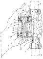
- the flow regulator has a main pipe 1 with a through channel 2, in which a flow regulating valve 3 lies.
- the liquid flows through it Main pipe 1 in the direction of an arrow 4.
- the main pipe 1 lies in a wiring harness 5.
- a measuring orifice 6 In the main pipe, in front of the Flow regulating valve 3 is a measuring orifice 6, their meaning explained in detail in DE-GM 82 20 193 is.
- a bypass line is located next to the main pipe 1 7, which is located at point 8 of the through channel 2 branches off and at point 9 back into the through channel 2 flows into.
- the bypass line 7 is by means of both valves 10 and 11 either from through channel 2 lockable or connectable to it.
- a flow meter 12 in the bypass line 7 is a flow meter 12, as he detailed in the two documents mentioned above is explained.
- the flow meter 12 has a Sight glass 13 movable piston, the front Face 14 with a scale, not shown, on the Sight glass 13 shows the respective flow rate.
- Each of the two valves 10 and 11 has one to be pushed against the force of a spring 16 or 17 Valve closing body 18 or 19.
- the valve 10 has one Tappet 20, and the valve 11 has a tappet 21.
- Die two plungers 20 and 21 are in a hand-operated Yoke 22 stored, which is in the drawing in the upper Half is in the actuated state, whereas it is in the drawing in the lower half in the non-actuated Condition.
- the two valves 10, 11 are thus through the yoke 22 against the force of their spring 16, 17 to open; when the yoke 22 is not actuated, the two Valves 10, 11 closed by the two springs 16, 17.
- the Yoke 22 essentially parallel to through-channel 2 and thus also parallel to the main pipe 1.
- the two Tappets 20 and 21 hit the valve closing bodies at one end 18, 19 and are swinging in the other end Yoke 22 stored. This ensures that the two plungers 20, 21 cannot tilt, too if the yoke 22 is not shifted exactly parallel.
- Each valve closing body 18, 19 carries a sealing washer 23, 24, which face the plungers 20, 21.
- the yoke 22 is U-shaped, the beam 25 the U-shape carries the two plungers 20, 21 and the legs 26 of the U-shape on both sides of a housing 27 of the Bypass line.
- This housing 27 has a guide rail 28, along which a pointer 29 is displaceable to display the target flow rate for the flow meter.
- the flow control device is also with Advantage mounted on the wiring harness 5 that the Yoke 22 of the operator faces so that through the ball of the hand both valves 10, 11 simultaneously are operated as well as the flow meter 12 at Sight glass 13 can be easily read.
- the simultaneous This also actuates the two valves 10, 11 guaranteed because the ball of the thumb also a kind Yoke with respect to the opposite four fingers is so that the yoke of the heel of the hand when actuated of the device is pressed against the yoke 22 of the device.
- the flow regulating valve 3 has a rotatable valve plug a spherical valve closing body with a through channel, as detailed in the two at the beginning mentioned documents is explained. So it's one continuous regulation of the flow rate possible.
- the Flow regulating valve can be operated manually (Control); the valve 3 can also in a control loop (Regulation) and by an actuator be operated.
- valves 10, 11 when the pressure in the Bypass line (by increasing the temperature) automatically to open. Should e.g. the flow meter 12 itself is leaking (e.g. defective sight glass 13) larger amount of liquid and therefore not worth mentioning Water damage because the two valves 10, 11 in the rest position the wiring harness 5 automatically to the outside cordon off.
Landscapes
- Physics & Mathematics (AREA)
- General Physics & Mathematics (AREA)
- Engineering & Computer Science (AREA)
- Fluid Mechanics (AREA)
- Power Engineering (AREA)
- Automation & Control Theory (AREA)
- Flow Control (AREA)
- Measuring Volume Flow (AREA)
- Control Of Non-Electrical Variables (AREA)
Abstract
Description
Claims (6)
- Durchflussreguliergerät für Flüssigkeiten, in dessen Durchgangskanal (2) ein Durchfluss-Regulierventil (3) liegt, und mit einer Bypass-Leitung (7) bezüglich des Durchgangskanals (2), welche Bypass-Leitung (7) mittels zweier Ventile (10, 11) entweder vom Durchgangskanal (2) abschliessbar oder mit diesem verbindbar ist, wobei sich in der Bypass-Leitung (7) ein Durchflussmesser (12) befindet, dadurch gekennzeichnet, dass jedes der beiden Ventile (10, 11) einen gegen Federkraft (16, 17) aufzustossenden Ventil-Schliesskörper (18, 19) aufweist, und dass die beiden Stössel (20, 21) der beiden Ventile (10, 11) mit einem einzigen handbetätigbaren Joch (22) bewegungsverbunden sind.
- Gerät nach Anspruch 1, dadurch gekennzeichnet, dass das Joch (22) im wesentlichen parallel zum Durchgangskanal (2) liegt, so dass der den Durchgangskanal (2) umgebende Gehäuseteil (1) und das Joch (22) dazu bestimmt sind, zusammen in der Hand einer Bedienungsperson zu liegen, zum Betätigen des Jochs (2).
- Gerät nach Anspruch 1 oder 2, dadurch gekennzeichnet, dass die beiden Stössel (20, 21) pendelnd im Joch (22) gelagert sind.
- Gerät nach einem der Ansprüche 1 bis 3, dadurch gekennzeichnet, dass die Ventilschliesskörper (18, 29) plattenförmig sind und je eine Abdichtscheibe (23 bzw. 24) tragen, die den Stösseln (20, 21) zugewandt sind.
- Gerät nach einem der Ansprüche 1 bis 4, dadurch gekennzeichnet, dass das Joch (22) U-förmig ist, wobei der Balken (25) der U-Form die beiden Stössel (20, 21) trägt und wobei die beiden Schenkel (26) der U-Form zu beiden Seiten eines Gehäuses (27) der Bypass-Leitung (7) liegen.
- Gerät nach Anspruch 5, dadurch gekennzeichnet, dass das Gehäuse (27) der Bypass-Leitung (7) eine Führungsschiene (28) mit einem längs dieser verschiebbaren Zeiger (29) aufweist, zum Anzeigen der Soll-Durchflussmenge am Durchflussmesser (12).
Applications Claiming Priority (2)
| Application Number | Priority Date | Filing Date | Title |
|---|---|---|---|
| DE29805136U | 1998-03-23 | ||
| DE29805136U DE29805136U1 (de) | 1998-03-23 | 1998-03-23 | Durchflußreguliergerät für Flüssigkeiten |
Publications (2)
| Publication Number | Publication Date |
|---|---|
| EP0945713A1 true EP0945713A1 (de) | 1999-09-29 |
| EP0945713B1 EP0945713B1 (de) | 2005-04-06 |
Family
ID=8054544
Family Applications (1)
| Application Number | Title | Priority Date | Filing Date |
|---|---|---|---|
| EP99105014A Expired - Lifetime EP0945713B1 (de) | 1998-03-23 | 1999-03-19 | Durchflussreguliergerät für Flüssigkeiten |
Country Status (4)
| Country | Link |
|---|---|
| EP (1) | EP0945713B1 (de) |
| AT (1) | ATE292788T1 (de) |
| DE (2) | DE29805136U1 (de) |
| ES (1) | ES2238787T3 (de) |
Cited By (1)
| Publication number | Priority date | Publication date | Assignee | Title |
|---|---|---|---|---|
| EP1978336A2 (de) | 2007-04-05 | 2008-10-08 | Caleffi S.p.A. | Durchflussratenstell- und Anzeigeventilvorrichtung für ein Fluid |
Citations (4)
| Publication number | Priority date | Publication date | Assignee | Title |
|---|---|---|---|---|
| DE3115572A1 (de) * | 1980-04-16 | 1982-03-25 | Taco Armaturen AG, 8048 Zürich | Durchflussreguliergeraet |
| DE8220193U1 (de) * | 1982-07-15 | 1982-10-21 | Taco Armaturen AG, 8048 Zürich | Durchflußreguliergerät |
| EP0465274A1 (de) * | 1990-07-02 | 1992-01-08 | Lamarque S.A. | Mechanische Dosiervorrichtung |
| GB2276656A (en) * | 1993-04-02 | 1994-10-05 | Sage Passant Peter | Water supply isolation system |
-
1998
- 1998-03-23 DE DE29805136U patent/DE29805136U1/de not_active Expired - Lifetime
-
1999
- 1999-03-19 EP EP99105014A patent/EP0945713B1/de not_active Expired - Lifetime
- 1999-03-19 ES ES99105014T patent/ES2238787T3/es not_active Expired - Lifetime
- 1999-03-19 AT AT99105014T patent/ATE292788T1/de active
- 1999-03-19 DE DE59911863T patent/DE59911863D1/de not_active Expired - Lifetime
Patent Citations (4)
| Publication number | Priority date | Publication date | Assignee | Title |
|---|---|---|---|---|
| DE3115572A1 (de) * | 1980-04-16 | 1982-03-25 | Taco Armaturen AG, 8048 Zürich | Durchflussreguliergeraet |
| DE8220193U1 (de) * | 1982-07-15 | 1982-10-21 | Taco Armaturen AG, 8048 Zürich | Durchflußreguliergerät |
| EP0465274A1 (de) * | 1990-07-02 | 1992-01-08 | Lamarque S.A. | Mechanische Dosiervorrichtung |
| GB2276656A (en) * | 1993-04-02 | 1994-10-05 | Sage Passant Peter | Water supply isolation system |
Cited By (2)
| Publication number | Priority date | Publication date | Assignee | Title |
|---|---|---|---|---|
| EP1978336A2 (de) | 2007-04-05 | 2008-10-08 | Caleffi S.p.A. | Durchflussratenstell- und Anzeigeventilvorrichtung für ein Fluid |
| EP1978336A3 (de) * | 2007-04-05 | 2014-08-27 | CALEFFI S.p.A. | Durchflussratenstell- und Anzeigeventilvorrichtung für ein Fluid |
Also Published As
| Publication number | Publication date |
|---|---|
| DE29805136U1 (de) | 1998-05-07 |
| ATE292788T1 (de) | 2005-04-15 |
| DE59911863D1 (de) | 2005-05-12 |
| EP0945713B1 (de) | 2005-04-06 |
| ES2238787T3 (es) | 2005-09-01 |
Similar Documents
| Publication | Publication Date | Title |
|---|---|---|
| EP0797080B1 (de) | Durchflussregulierventil mit Durchflussmesser | |
| DE3115572A1 (de) | Durchflussreguliergeraet | |
| EP0945713B1 (de) | Durchflussreguliergerät für Flüssigkeiten | |
| DE3124944A1 (de) | "hochdruckreiniger" | |
| DE3431800A1 (de) | Spritzpistole | |
| DE838098C (de) | Absperrorgan mit Rohrschiebern | |
| DE962250C (de) | Fluessigkeitssteuerung an Doppelaggregaten | |
| DE2741897A1 (de) | Mischventil | |
| DE2235876A1 (de) | Regelventil | |
| DE19701401A1 (de) | Gas-Druckregelgerät | |
| DE19802240A1 (de) | Stufenloses automatisch-mechanisches Schaum-Dosiersystem für Hoch- und Normaldruck Feuerlöschkreiselpumpen | |
| DE801871C (de) | Steuerorgan fuer die Mengen- und Druckregelung eines gasfoermigen oder fluessigen Mediums in Rohrleitungen | |
| DE3127738A1 (de) | Mengenregulierventil | |
| DE1119141B (de) | Selbsttaetig schliessende Zapfpistole | |
| DE4326352C2 (de) | Fluid-Kanalvorrichtung für Haushaltgeräte | |
| DE1116953B (de) | Mischventil | |
| DE3539757C2 (de) | ||
| DE350836C (de) | Drehschieber fuer Rohrleitungen | |
| DE32480C (de) | Gasdruckregulator | |
| DE727642C (de) | Sicherheitszuendvorrichtung fuer Gasbrenner | |
| DE10352273B4 (de) | Automatische Wechselduscharmatur | |
| DE258512C (de) | ||
| DE2639264A1 (de) | Zahnaerztliches geraet | |
| DE701982C (de) | Fernbetaetigte Absperrvorrichtung fuer Brennstoff- oder andere Fluessigkeitsleitungen in Luftfahrzeugen | |
| DE522192C (de) | Wasserhahn mit im Gehaeuse eingebautem, elektrischem Heizkoerper |
Legal Events
| Date | Code | Title | Description |
|---|---|---|---|
| PUAI | Public reference made under article 153(3) epc to a published international application that has entered the european phase |
Free format text: ORIGINAL CODE: 0009012 |
|
| AK | Designated contracting states |
Kind code of ref document: A1 Designated state(s): AT BE CH DE DK ES FI FR GB GR IE IT LI NL PT SE |
|
| AX | Request for extension of the european patent |
Free format text: AL;LT;LV;MK;RO;SI |
|
| 17P | Request for examination filed |
Effective date: 19991203 |
|
| AKX | Designation fees paid |
Free format text: AT BE CH DE DK ES FI FR GB GR IE IT LI NL PT SE |
|
| GRAP | Despatch of communication of intention to grant a patent |
Free format text: ORIGINAL CODE: EPIDOSNIGR1 |
|
| GRAS | Grant fee paid |
Free format text: ORIGINAL CODE: EPIDOSNIGR3 |
|
| GRAA | (expected) grant |
Free format text: ORIGINAL CODE: 0009210 |
|
| AK | Designated contracting states |
Kind code of ref document: B1 Designated state(s): AT BE CH DE DK ES FI FR GB GR IE IT LI NL PT SE |
|
| PG25 | Lapsed in a contracting state [announced via postgrant information from national office to epo] |
Ref country code: NL Free format text: LAPSE BECAUSE OF FAILURE TO SUBMIT A TRANSLATION OF THE DESCRIPTION OR TO PAY THE FEE WITHIN THE PRESCRIBED TIME-LIMIT Effective date: 20050406 Ref country code: IE Free format text: LAPSE BECAUSE OF FAILURE TO SUBMIT A TRANSLATION OF THE DESCRIPTION OR TO PAY THE FEE WITHIN THE PRESCRIBED TIME-LIMIT Effective date: 20050406 Ref country code: FI Free format text: LAPSE BECAUSE OF FAILURE TO SUBMIT A TRANSLATION OF THE DESCRIPTION OR TO PAY THE FEE WITHIN THE PRESCRIBED TIME-LIMIT Effective date: 20050406 |
|
| REG | Reference to a national code |
Ref country code: GB Ref legal event code: FG4D Free format text: NOT ENGLISH |
|
| REG | Reference to a national code |
Ref country code: CH Ref legal event code: NV Representative=s name: E. BLUM & CO. PATENTANWAELTE Ref country code: CH Ref legal event code: EP |
|
| REG | Reference to a national code |
Ref country code: IE Ref legal event code: FG4D Free format text: LANGUAGE OF EP DOCUMENT: GERMAN |
|
| REF | Corresponds to: |
Ref document number: 59911863 Country of ref document: DE Date of ref document: 20050512 Kind code of ref document: P |
|
| PG25 | Lapsed in a contracting state [announced via postgrant information from national office to epo] |
Ref country code: SE Free format text: LAPSE BECAUSE OF FAILURE TO SUBMIT A TRANSLATION OF THE DESCRIPTION OR TO PAY THE FEE WITHIN THE PRESCRIBED TIME-LIMIT Effective date: 20050706 Ref country code: GR Free format text: LAPSE BECAUSE OF FAILURE TO SUBMIT A TRANSLATION OF THE DESCRIPTION OR TO PAY THE FEE WITHIN THE PRESCRIBED TIME-LIMIT Effective date: 20050706 Ref country code: DK Free format text: LAPSE BECAUSE OF FAILURE TO SUBMIT A TRANSLATION OF THE DESCRIPTION OR TO PAY THE FEE WITHIN THE PRESCRIBED TIME-LIMIT Effective date: 20050706 |
|
| GBT | Gb: translation of ep patent filed (gb section 77(6)(a)/1977) |
Effective date: 20050725 |
|
| REG | Reference to a national code |
Ref country code: ES Ref legal event code: FG2A Ref document number: 2238787 Country of ref document: ES Kind code of ref document: T3 |
|
| PG25 | Lapsed in a contracting state [announced via postgrant information from national office to epo] |
Ref country code: PT Free format text: LAPSE BECAUSE OF FAILURE TO SUBMIT A TRANSLATION OF THE DESCRIPTION OR TO PAY THE FEE WITHIN THE PRESCRIBED TIME-LIMIT Effective date: 20050908 |
|
| NLV1 | Nl: lapsed or annulled due to failure to fulfill the requirements of art. 29p and 29m of the patents act | ||
| REG | Reference to a national code |
Ref country code: IE Ref legal event code: FD4D |
|
| ET | Fr: translation filed | ||
| PLBE | No opposition filed within time limit |
Free format text: ORIGINAL CODE: 0009261 |
|
| STAA | Information on the status of an ep patent application or granted ep patent |
Free format text: STATUS: NO OPPOSITION FILED WITHIN TIME LIMIT |
|
| 26N | No opposition filed |
Effective date: 20060110 |
|
| PG25 | Lapsed in a contracting state [announced via postgrant information from national office to epo] |
Ref country code: BE Free format text: LAPSE BECAUSE OF NON-PAYMENT OF DUE FEES Effective date: 20060331 |
|
| REG | Reference to a national code |
Ref country code: CH Ref legal event code: PFA Owner name: OSTACO AG Free format text: OSTACO AG#STEINACKERSTRASSE 6#8902 URDORF (CH) -TRANSFER TO- OSTACO AG#STEINACKERSTRASSE 6#8902 URDORF (CH) |
|
| BERE | Be: lapsed |
Owner name: OSTACO A.G. Effective date: 20060331 |
|
| REG | Reference to a national code |
Ref country code: FR Ref legal event code: PLFP Year of fee payment: 18 |
|
| PGFP | Annual fee paid to national office [announced via postgrant information from national office to epo] |
Ref country code: ES Payment date: 20160309 Year of fee payment: 18 |
|
| PGFP | Annual fee paid to national office [announced via postgrant information from national office to epo] |
Ref country code: FR Payment date: 20160321 Year of fee payment: 18 Ref country code: GB Payment date: 20160321 Year of fee payment: 18 |
|
| PGFP | Annual fee paid to national office [announced via postgrant information from national office to epo] |
Ref country code: IT Payment date: 20160324 Year of fee payment: 18 |
|
| REG | Reference to a national code |
Ref country code: CH Ref legal event code: PFA Owner name: TACONOVA GROUP AG, CH Free format text: FORMER OWNER: OSTACO AG, CH |
|
| REG | Reference to a national code |
Ref country code: DE Ref legal event code: R082 Ref document number: 59911863 Country of ref document: DE Representative=s name: MAMMEL UND MASER, PATENTANWAELTE, DE Ref country code: DE Ref legal event code: R081 Ref document number: 59911863 Country of ref document: DE Owner name: TACONOVA GROUP AG, CH Free format text: FORMER OWNER: OSTACO AG, URDORF, CH |
|
| REG | Reference to a national code |
Ref country code: GB Ref legal event code: 732E Free format text: REGISTERED BETWEEN 20170331 AND 20170405 |
|
| REG | Reference to a national code |
Ref country code: FR Ref legal event code: CD Owner name: OSTACO AG Effective date: 20170522 Ref country code: FR Ref legal event code: CA Effective date: 20170522 |
|
| REG | Reference to a national code |
Ref country code: AT Ref legal event code: HC Ref document number: 292788 Country of ref document: AT Kind code of ref document: T Owner name: TACONOVA GROUP AG, CH Effective date: 20170814 |
|
| GBPC | Gb: european patent ceased through non-payment of renewal fee |
Effective date: 20170319 |
|
| REG | Reference to a national code |
Ref country code: FR Ref legal event code: ST Effective date: 20171130 |
|
| PG25 | Lapsed in a contracting state [announced via postgrant information from national office to epo] |
Ref country code: FR Free format text: LAPSE BECAUSE OF NON-PAYMENT OF DUE FEES Effective date: 20170331 |
|
| PG25 | Lapsed in a contracting state [announced via postgrant information from national office to epo] |
Ref country code: GB Free format text: LAPSE BECAUSE OF NON-PAYMENT OF DUE FEES Effective date: 20170319 Ref country code: IT Free format text: LAPSE BECAUSE OF NON-PAYMENT OF DUE FEES Effective date: 20170319 |
|
| PGFP | Annual fee paid to national office [announced via postgrant information from national office to epo] |
Ref country code: CH Payment date: 20180202 Year of fee payment: 20 Ref country code: DE Payment date: 20180322 Year of fee payment: 20 |
|
| REG | Reference to a national code |
Ref country code: ES Ref legal event code: FD2A Effective date: 20180507 |
|
| PGFP | Annual fee paid to national office [announced via postgrant information from national office to epo] |
Ref country code: AT Payment date: 20180322 Year of fee payment: 20 |
|
| PG25 | Lapsed in a contracting state [announced via postgrant information from national office to epo] |
Ref country code: ES Free format text: LAPSE BECAUSE OF NON-PAYMENT OF DUE FEES Effective date: 20170320 |
|
| REG | Reference to a national code |
Ref country code: DE Ref legal event code: R071 Ref document number: 59911863 Country of ref document: DE |
|
| REG | Reference to a national code |
Ref country code: CH Ref legal event code: PL |
|
| REG | Reference to a national code |
Ref country code: AT Ref legal event code: MK07 Ref document number: 292788 Country of ref document: AT Kind code of ref document: T Effective date: 20190319 |