EP0943393A2 - Dispositif d' assemblage des éléments - Google Patents
Dispositif d' assemblage des éléments Download PDFInfo
- Publication number
- EP0943393A2 EP0943393A2 EP99102890A EP99102890A EP0943393A2 EP 0943393 A2 EP0943393 A2 EP 0943393A2 EP 99102890 A EP99102890 A EP 99102890A EP 99102890 A EP99102890 A EP 99102890A EP 0943393 A2 EP0943393 A2 EP 0943393A2
- Authority
- EP
- European Patent Office
- Prior art keywords
- rail
- receiving part
- component
- components
- receiving
- Prior art date
- Legal status (The legal status is an assumption and is not a legal conclusion. Google has not performed a legal analysis and makes no representation as to the accuracy of the status listed.)
- Granted
Links
Images
Classifications
-
- B—PERFORMING OPERATIONS; TRANSPORTING
- B25—HAND TOOLS; PORTABLE POWER-DRIVEN TOOLS; MANIPULATORS
- B25B—TOOLS OR BENCH DEVICES NOT OTHERWISE PROVIDED FOR, FOR FASTENING, CONNECTING, DISENGAGING OR HOLDING
- B25B23/00—Details of, or accessories for, spanners, wrenches, screwdrivers
- B25B23/02—Arrangements for handling screws or nuts
- B25B23/04—Arrangements for handling screws or nuts for feeding screws or nuts
-
- B—PERFORMING OPERATIONS; TRANSPORTING
- B23—MACHINE TOOLS; METAL-WORKING NOT OTHERWISE PROVIDED FOR
- B23P—METAL-WORKING NOT OTHERWISE PROVIDED FOR; COMBINED OPERATIONS; UNIVERSAL MACHINE TOOLS
- B23P19/00—Machines for simply fitting together or separating metal parts or objects, or metal and non-metal parts, whether or not involving some deformation; Tools or devices therefor so far as not provided for in other classes
- B23P19/001—Article feeders for assembling machines
- B23P19/006—Holding or positioning the article in front of the applying tool
-
- B—PERFORMING OPERATIONS; TRANSPORTING
- B25—HAND TOOLS; PORTABLE POWER-DRIVEN TOOLS; MANIPULATORS
- B25B—TOOLS OR BENCH DEVICES NOT OTHERWISE PROVIDED FOR, FOR FASTENING, CONNECTING, DISENGAGING OR HOLDING
- B25B23/00—Details of, or accessories for, spanners, wrenches, screwdrivers
- B25B23/02—Arrangements for handling screws or nuts
- B25B23/04—Arrangements for handling screws or nuts for feeding screws or nuts
- B25B23/06—Arrangements for handling screws or nuts for feeding screws or nuts using built-in magazine
Definitions
- the invention relates to a device for conveying and assembling of components to be inserted in a workpiece, which are used in a magazine serving rail are guided at one end for acceptance of a component has an opening.
- Such a device is known from US Pat. No. 2,344,127. With this Device blind rivets are processed, one after the other in a rail are suspended and in the rail by a spring tension Towards the end of the rail. At the end of the rail a mechanism is provided which closes its opening here and only one single blind rivet can be removed. This acceptance is carried out by means of an attached to a setting tool Lever, which is pivotally mounted about an axis on the setting tool is. The lever is used to remove one before opening the rail hanging blind rivets pivoted towards this opening, the lever can grasp a single blind rivet and swivel it into a position, in which the blind rivet is inserted in the setting tool.
- the rail is on Setting tool attached to the side and thus forms a uniform device together with the setting tool.
- the one for taking one Blind rivets necessary mechanism with simultaneous unlocking of the rail has a complicated structure and is free on the setting tool from the outside attached accessible, so that the removal mechanism can easily be damaged. It's also about that a relatively complicated construction.
- the invention has for its object a device for conveying and assembly of components to be inserted into a workpiece specified type to create the sturdy and compact design is equipped with few parts.
- This happens according to the invention characterized in that the opening in a joint connected to the rail and passes with this aligned receiving part for a single component and the rail with the receiving part longitudinally displaceable in one Guide is mounted in which the receiving part for receiving a component in the retracted position of the rail in alignment with the rail Holding position is held, wherein the receiving part is arranged that when the rail advances, the receiving part with the component protrudes from the guide and through the joint by about 90 ° into an ejection position kinks in which the component is assembled by a plunger arranged next to the guide can be ejected from the receiving part and can be assembled in a workpiece.
- the receiving part held in alignment with the rail acts in the retracted position of the rail as part of the Rail from which the receiving part only when the rail is pushed forward has to bend to the ejection position together with a component reach.
- the mobility of the receiving part relative to the rail is thereby ensured by the joint that the receiving part with the Rail is connected, which are simply designed components.
- the construction of the device forms a closed arrangement, only the relatively short receiving part in the ejection position is kinked, thus securing the entire device from damage is trained.
- the receiving part from the ejection position into its receiving position aligned with the rail is pivoted back by a deflection part attached to the opening, so that under the action of the stop the foremost in the rail guided component slides into the receiving part, the deflecting part at Advancing the rail, kinking the receiving part into the eject position directs.
- the deflecting part which e.g. through one at the end of the rail attached rounding can be formed is a simply designed construction part, only when pushing the rail forward and back the movement of the receiving part from the receiving position to the eject position and has to steer back.
- the components are usefully guided in lateral longitudinal grooves in the Rail into which the protrusions of the components fit.
- a locking device is expediently arranged on the guide, which detachably holds the receiving part in the eject position. If so Device with the receiving part in the ejection position somehow moved relative to a workpiece, in particular in a vertical position is guided and held therein, the locking device holds the receiving part firmly in its eject position so that it is under the influence gravity cannot swing. For the locking device you can use a magnet, although with its relatively low Force holds the receiving part in the eject position, but the receiving part when pulling back the rail releases easily, so that this can be pivoted back and transferred into its receiving position.
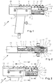
- the device for conveying and mounting of components 8 shown for the purpose of cheap handling is provided with the handle 1, into which a feed channel 2 opens, the for supplying electrical or pneumatic energy, for example serves.
- the button 3 is attached to the handle 1 when it is actuated in the usual way the housed in the housing 4 in Activity.
- the guide 5 is housed, the side of the
- the rail 7 is mounted in the guide 5, which is carried in a longitudinally displaceable manner by the guide 5 (see also Figure 9).
- the rail 7 serving as a magazine here carries eight components 8, which are plastic inserts that are in a workpiece are to be used (see Figures 5 and 6). Different types of components can of course also be processed.
- the receiving part 9 is rotatably articulated, specifically via the joint 10, of which only the axis is shown in Figure 1.
- the receiving part 9 is shown in Figures 1 and 2 in alignment with the rail 7, which is the receiving position of the receiving part 9. In this receiving position, the receiving part 9 stands for the recording of a component 8 ready.
- the rail 7 carried longitudinally displaceably by the guide 5 can be by means of the handles 11 (see FIG. 2) which move through elongated holes 12 reach through in the side walls 6 and on the rail 7 at the fastening point 13 are attached.
- the handles 11 towards the left opposite the end 14 of the side walls 6 and the Guide 5 shifted (see arrow in Fig. 3), being from the rail 7 worn components 8 are carried along until the first component 15 abuts the stop 16, which bridges the side walls 6 on the Housing 4 is attached.
- the stop 16 the component 15 and so that the components 8 arranged to the right are held so that the rail 7 below them moves to the left, due to the with the rail 7 aligned position of the receiving part 9, the foremost component 17 through the opening 33 (see FIG. 2) of the rail 7 into the receiving part 9 is pushed.
- the penultimate component 27 comes into the position of Component 17 shown in Figure 1 that, as Figure 3 shows, finally is pushed up to the end wall 18 (see FIG. 2).
- the recording part 9 is thus loaded with one component, namely component 17. This position is shown in Figure 3.
- the receiving part 9 in kept in alignment with the rail 7 position constantly, namely in that both the rail 7 and the receiving part 9 compared to the Support guide 5.
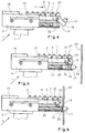
- the components 8 in the previously described Moved in the direction of the end wall 18 of the receiving part are, finally the component 17 in that shown in Figure 3
- the device is now ready in its eject position to be convicted. This is now shown in FIGS. 4 and 5 described.
- the rail 7 by moving the handles accordingly 11 moved away from the stop 16 (see arrow in Fig. 4), wherein the receiving part 9, which initially over the end 14 of the side walls 6 protrudes (see Figures 1 and 2) pushed further in front of said end 14 is, so that now the receiving part 9 relative to the rail 7 in a broken position can be transferred.
- the end region of the guide 5 facing the end 14 with a provided as a deflecting curve 19 the receiving part 9 at the advance of which is an even kinking relative to the rail 7 allows until the rail 7 finally that shown in Figure 5 Has reached position in which the receiving part 9 has passed into the ejection position is.
- the receiving part 9 is 90 ° relative to the rail 7 kinked.
- the joint contains 10 for kinking the Receiving part 9, the two prongs 20 of the receiving part 9, which between the side walls 6 and the corresponding parts of the guide 7 grip, which gives the receiving part 9 the necessary rotational mobility.
- the tines 20 provided on its side facing the rail 7 with the curvature 22.
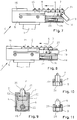
- FIG. 11 shows another mounting of the components 8, which is done by clamping means 34 is formed on component 8.
- This magnet 32 acts as an articulation device, which the receiving part 9 in the ejection position shown in Figure 5 releasably holds. After the device has assumed this position, it can be moved back and forth in all possible positions, whereby of course, gravity acts on the receiving part 9 without this can be shifted from its ejection position. Furthermore causes the magnet 32 that when moving the rail 7 (like. arrow direction from Figure 4), so when moving. Figures 4 and 5, the receiving part 9 is constantly pulled against the curve 19, that is a position favored by gravity not from the rail 7 can be pulled away.
- the receiving part 9 follows the curve 19 independent of a simultaneous movement of the device, whereby the receiving part 9 hugs the curve 19 until finally the ejection position of the receiving part 9 shown in FIG. 5 has been reached.
- the magnet other energy storage e.g. B.
- a spring any one instead of the magnet other energy storage
Landscapes
- Engineering & Computer Science (AREA)
- Mechanical Engineering (AREA)
- Automatic Assembly (AREA)
- Portable Nailing Machines And Staplers (AREA)
- Warehouses Or Storage Devices (AREA)
Applications Claiming Priority (2)
| Application Number | Priority Date | Filing Date | Title |
|---|---|---|---|
| DE19812085A DE19812085A1 (de) | 1998-03-19 | 1998-03-19 | Montiervorrichtung für Bauteile |
| DE19812085 | 1998-03-19 |
Publications (3)
| Publication Number | Publication Date |
|---|---|
| EP0943393A2 true EP0943393A2 (fr) | 1999-09-22 |
| EP0943393A3 EP0943393A3 (fr) | 2001-01-10 |
| EP0943393B1 EP0943393B1 (fr) | 2002-10-09 |
Family
ID=7861549
Family Applications (1)
| Application Number | Title | Priority Date | Filing Date |
|---|---|---|---|
| EP99102890A Expired - Lifetime EP0943393B1 (fr) | 1998-03-19 | 1999-03-04 | Dispositif d' assemblage des éléments |
Country Status (5)
| Country | Link |
|---|---|
| US (1) | US6145726A (fr) |
| EP (1) | EP0943393B1 (fr) |
| JP (1) | JP4019238B2 (fr) |
| DE (2) | DE19812085A1 (fr) |
| ES (1) | ES2182412T3 (fr) |
Cited By (1)
| Publication number | Priority date | Publication date | Assignee | Title |
|---|---|---|---|---|
| WO2001043913A1 (fr) * | 1999-12-17 | 2001-06-21 | Bas Components Limited | Presse et systeme d'alimentation pour une presse |
Families Citing this family (8)
| Publication number | Priority date | Publication date | Assignee | Title |
|---|---|---|---|---|
| JP4227640B2 (ja) * | 2005-11-11 | 2009-02-18 | キヤノン株式会社 | シート処理装置、これを備えた画像形成装置 |
| DE102015210233A1 (de) * | 2015-06-03 | 2016-12-08 | Bayerische Motoren Werke Aktiengesellschaft | Blindnietgerät mit Haltevorrichtung für Nietdorne |
| DE102015211543B4 (de) | 2015-06-23 | 2022-10-06 | Bayerische Motoren Werke Aktiengesellschaft | Handwerkzeug zum Setzen von Stopfen mit Handabzug |
| GB2569126A (en) | 2017-12-05 | 2019-06-12 | Atlas Copco Ias Uk Ltd | Fastener magazines, and related supply systems and methods |
| GB2569127A (en) | 2017-12-05 | 2019-06-12 | Atlas Copco Ias Uk Ltd | Nose arrangements for fastener setting machines, and related methods |
| GB2569122A (en) | 2017-12-05 | 2019-06-12 | Atlas Copco Ias Uk Ltd | Fastener handling devices for fastener setting machines, and related methods |
| CN110465737B (zh) | 2018-05-09 | 2023-11-21 | 杨百翰大学 | 用于摩擦钻头接合的系统和方法 |
| US11117183B1 (en) * | 2020-04-10 | 2021-09-14 | The Boeing Company | End effectors and feeders for swaging operations |
Citations (4)
| Publication number | Priority date | Publication date | Assignee | Title |
|---|---|---|---|---|
| US4528874A (en) * | 1983-01-17 | 1985-07-16 | Dunn J Malcolm | Screw fasteners and drivers |
| US5207085A (en) * | 1991-11-13 | 1993-05-04 | S.A.R.G. Research Associates, Ltd. | Automatic blind rivet setting device |
| US5351392A (en) * | 1990-12-06 | 1994-10-04 | Huck International, Inc. | Automatic rivet feed apparatus |
| DE19609456A1 (de) * | 1996-03-11 | 1997-09-18 | Emhart Inc | Einrichtung zum Anbringen von Befestigungselementen an einer Struktur und ein Verfahren zum Bestücken einer Befestigungseinrichtung |
Family Cites Families (16)
| Publication number | Priority date | Publication date | Assignee | Title |
|---|---|---|---|---|
| US2344127A (en) * | 1940-08-03 | 1944-03-14 | Carl W Cherry | Riveting apparatus |
| US2507047A (en) * | 1944-05-02 | 1950-05-09 | Douglas Aircraft Co Inc | Rivet feeding attachment |
| US2495070A (en) * | 1945-02-27 | 1950-01-17 | Glenn L Martin Co | Fastener handling device |
| US3802617A (en) * | 1971-05-11 | 1974-04-09 | Kaynar Mfg Co | Powered fastener driving tool |
| DE2737602A1 (de) * | 1977-08-20 | 1979-03-01 | Raymond A Fa | Befestigung einer pufferleiste auf einer traegerwand |
| US4339065A (en) * | 1978-07-24 | 1982-07-13 | Haytayan Harry M | Pneumatic tool |
| JPS5852795B2 (ja) * | 1979-01-22 | 1983-11-25 | 庸人 奥田 | 画鋲差付け装置 |
| US4495841A (en) * | 1982-04-21 | 1985-01-29 | Matsushita Electric Industrial Co., Ltd. | Automatic screwdriver |
| DE3444025A1 (de) * | 1984-12-03 | 1986-06-05 | Tucker Gmbh, 6300 Giessen | Vorrichtung zum beschicken eines werkzeuges mit einem bauteil |
| GB2180482B (en) * | 1985-09-19 | 1989-01-25 | Avdel Ltd | Apparatus for installing fasteners |
| US4628722A (en) * | 1986-02-14 | 1986-12-16 | Usm Corporation | Setting tool for rivet with pull-headed mandrel |
| US5239900A (en) * | 1991-10-01 | 1993-08-31 | James Macris | Power screwdriver automatic loading apparatus |
| US5144870A (en) * | 1991-10-18 | 1992-09-08 | Nick Edward V | Apparatus for selectively installing fasteners |
| DE4335668C2 (de) * | 1993-10-20 | 2002-10-17 | Hydro Control Steuerungstechni | Nietsetzgerät mit automatischer Zuführung |
| US5640758A (en) * | 1995-04-12 | 1997-06-24 | Emhart Inc. | Component feeder with reciprocal and rotatable magazine |
| DE19643656A1 (de) * | 1996-10-22 | 1998-04-23 | Emhart Inc | Befestigungsvorrichtung zum Anbringen von Befestigungselementen an einer Struktur und ein Verfahren zum Bestücken einer Befestigungseinrichtung |
-
1998
- 1998-03-19 DE DE19812085A patent/DE19812085A1/de not_active Withdrawn
-
1999
- 1999-03-04 DE DE59902992T patent/DE59902992D1/de not_active Expired - Fee Related
- 1999-03-04 EP EP99102890A patent/EP0943393B1/fr not_active Expired - Lifetime
- 1999-03-04 ES ES99102890T patent/ES2182412T3/es not_active Expired - Lifetime
- 1999-03-17 JP JP07218799A patent/JP4019238B2/ja not_active Expired - Fee Related
- 1999-03-19 US US09/272,294 patent/US6145726A/en not_active Expired - Fee Related
Patent Citations (4)
| Publication number | Priority date | Publication date | Assignee | Title |
|---|---|---|---|---|
| US4528874A (en) * | 1983-01-17 | 1985-07-16 | Dunn J Malcolm | Screw fasteners and drivers |
| US5351392A (en) * | 1990-12-06 | 1994-10-04 | Huck International, Inc. | Automatic rivet feed apparatus |
| US5207085A (en) * | 1991-11-13 | 1993-05-04 | S.A.R.G. Research Associates, Ltd. | Automatic blind rivet setting device |
| DE19609456A1 (de) * | 1996-03-11 | 1997-09-18 | Emhart Inc | Einrichtung zum Anbringen von Befestigungselementen an einer Struktur und ein Verfahren zum Bestücken einer Befestigungseinrichtung |
Cited By (2)
| Publication number | Priority date | Publication date | Assignee | Title |
|---|---|---|---|---|
| WO2001043913A1 (fr) * | 1999-12-17 | 2001-06-21 | Bas Components Limited | Presse et systeme d'alimentation pour une presse |
| US6990897B2 (en) | 1999-12-17 | 2006-01-31 | Bas Components Limited | Press and delivery system for a press |
Also Published As
| Publication number | Publication date |
|---|---|
| ES2182412T3 (es) | 2003-03-01 |
| JP4019238B2 (ja) | 2007-12-12 |
| EP0943393B1 (fr) | 2002-10-09 |
| JPH11309680A (ja) | 1999-11-09 |
| DE59902992D1 (de) | 2002-11-14 |
| DE19812085A1 (de) | 1999-09-23 |
| EP0943393A3 (fr) | 2001-01-10 |
| US6145726A (en) | 2000-11-14 |
Similar Documents
| Publication | Publication Date | Title |
|---|---|---|
| EP1921948B1 (fr) | Dispositif de poussée pouvant être bloqué | |
| DE3051048C2 (de) | Klemmenmagazin zur Verwendung mit einem chirurgischen Instrument | |
| DE102007014903B3 (de) | Auswechselbares Gesenk für Zangen, Zange mit einem solchen Gesenk und Aufbewahrungsvorrichtung | |
| DE60122091T2 (de) | Zuführvorrichtung von Nagelstreifen für Nagelmaschinen | |
| DE69218646T2 (de) | Injektionsvorrichtung | |
| DE2721210A1 (de) | Geraet zum anbringen von schildchen an geweben o.dgl. mittels anhaengern | |
| DE102020103316A1 (de) | Block zum Aufnehmen von Werkzeugelementen in einer Werkzeuganordnung | |
| DE3033539A1 (de) | Vorrichtung zur abgabe von befestigungselementen | |
| EP0943393B1 (fr) | Dispositif d' assemblage des éléments | |
| DE4201289A1 (de) | Vorrichtung zur handhabung von werkstuecken | |
| EP0707925B1 (fr) | Couteau à lame échangeable tel que couteau d'ébavurage de pièces en matière plastique ou analoques | |
| DE4312817A1 (de) | Ohrdurchstechvorrichtung für einen nicht entfernbaren Ohrring mit Kupplung | |
| DE3623495A1 (de) | Handgeraet zum anbringen von schildchen | |
| DE3301803C2 (de) | Ausziehvorrichtung für eine chirurgische Klammer | |
| DE19502526C1 (de) | Rollschubkastenregal | |
| DE3411138C2 (fr) | ||
| DE202011104824U1 (de) | Vorrichtung für die Öffnungsbewegung eines an einem Möbelkorpus eines Möbels aufgenommenen Möbelteils insbesondere Möbelteilöffnungsvorrichtung | |
| DE1608089B2 (de) | Anfahrstrang fuer stranggiessvorrichtungen | |
| AT503881B1 (de) | Entkoppelungsvorrichtung für eine schublade | |
| DE2441707A1 (de) | Automatisches blindnietgeraet | |
| DE20105767U1 (de) | Tragbare Werkzeugmaschine mit integrierter Bitschublade | |
| DE102009007292A1 (de) | Klingenschutzvorrichtung für Skalpellklinge und Skalpell | |
| DE2537318A1 (de) | Handgeraet zum absaugen von festen, fluessigen oder geschmolzenen partikeln | |
| DE10105847B4 (de) | Mitnahmevorrichtung für ausziehbaren Möbelboden | |
| DE3120247A1 (de) | "bohrvorrichtung fuer eine motorbetriebene handbohrmaschine" |
Legal Events
| Date | Code | Title | Description |
|---|---|---|---|
| PUAI | Public reference made under article 153(3) epc to a published international application that has entered the european phase |
Free format text: ORIGINAL CODE: 0009012 |
|
| AK | Designated contracting states |
Kind code of ref document: A2 Designated state(s): DE ES FR GB |
|
| AX | Request for extension of the european patent |
Free format text: AL;LT;LV;MK;RO;SI |
|
| PUAL | Search report despatched |
Free format text: ORIGINAL CODE: 0009013 |
|
| AK | Designated contracting states |
Kind code of ref document: A3 Designated state(s): AT BE CH CY DE DK ES FI FR GB GR IE IT LI LU MC NL PT SE |
|
| AX | Request for extension of the european patent |
Free format text: AL;LT;LV;MK;RO;SI |
|
| RIC1 | Information provided on ipc code assigned before grant |
Free format text: 7B 23P 19/00 A, 7B 25B 23/04 B, 7B 25B 23/06 B, 7B 21J 15/32 B |
|
| 17P | Request for examination filed |
Effective date: 20001214 |
|
| 17Q | First examination report despatched |
Effective date: 20010305 |
|
| AKX | Designation fees paid |
Free format text: DE ES FR GB |
|
| GRAG | Despatch of communication of intention to grant |
Free format text: ORIGINAL CODE: EPIDOS AGRA |
|
| GRAG | Despatch of communication of intention to grant |
Free format text: ORIGINAL CODE: EPIDOS AGRA |
|
| GRAH | Despatch of communication of intention to grant a patent |
Free format text: ORIGINAL CODE: EPIDOS IGRA |
|
| GRAH | Despatch of communication of intention to grant a patent |
Free format text: ORIGINAL CODE: EPIDOS IGRA |
|
| GRAA | (expected) grant |
Free format text: ORIGINAL CODE: 0009210 |
|
| AK | Designated contracting states |
Kind code of ref document: B1 Designated state(s): DE ES FR GB |
|
| PG25 | Lapsed in a contracting state [announced via postgrant information from national office to epo] |
Ref country code: FR Free format text: LAPSE BECAUSE OF FAILURE TO SUBMIT A TRANSLATION OF THE DESCRIPTION OR TO PAY THE FEE WITHIN THE PRESCRIBED TIME-LIMIT Effective date: 20021009 |
|
| REG | Reference to a national code |
Ref country code: GB Ref legal event code: FG4D Free format text: NOT ENGLISH |
|
| GBT | Gb: translation of ep patent filed (gb section 77(6)(a)/1977) |
Effective date: 20021009 |
|
| REF | Corresponds to: |
Ref document number: 59902992 Country of ref document: DE Date of ref document: 20021114 |
|
| REG | Reference to a national code |
Ref country code: ES Ref legal event code: FG2A Ref document number: 2182412 Country of ref document: ES Kind code of ref document: T3 |
|
| PG25 | Lapsed in a contracting state [announced via postgrant information from national office to epo] |
Ref country code: GB Free format text: LAPSE BECAUSE OF NON-PAYMENT OF DUE FEES Effective date: 20030304 |
|
| PG25 | Lapsed in a contracting state [announced via postgrant information from national office to epo] |
Ref country code: ES Free format text: LAPSE BECAUSE OF NON-PAYMENT OF DUE FEES Effective date: 20030305 |
|
| EN | Fr: translation not filed | ||
| PLBE | No opposition filed within time limit |
Free format text: ORIGINAL CODE: 0009261 |
|
| STAA | Information on the status of an ep patent application or granted ep patent |
Free format text: STATUS: NO OPPOSITION FILED WITHIN TIME LIMIT |
|
| 26N | No opposition filed |
Effective date: 20030710 |
|
| GBPC | Gb: european patent ceased through non-payment of renewal fee | ||
| REG | Reference to a national code |
Ref country code: ES Ref legal event code: FD2A Effective date: 20030305 |
|
| PGFP | Annual fee paid to national office [announced via postgrant information from national office to epo] |
Ref country code: DE Payment date: 20090313 Year of fee payment: 11 |
|
| PG25 | Lapsed in a contracting state [announced via postgrant information from national office to epo] |
Ref country code: DE Free format text: LAPSE BECAUSE OF NON-PAYMENT OF DUE FEES Effective date: 20101001 |