EP0943386A2 - Gewindeschneidwerkzeug und dessen Fertigungsmethode - Google Patents
Gewindeschneidwerkzeug und dessen Fertigungsmethode Download PDFInfo
- Publication number
- EP0943386A2 EP0943386A2 EP98630066A EP98630066A EP0943386A2 EP 0943386 A2 EP0943386 A2 EP 0943386A2 EP 98630066 A EP98630066 A EP 98630066A EP 98630066 A EP98630066 A EP 98630066A EP 0943386 A2 EP0943386 A2 EP 0943386A2
- Authority
- EP
- European Patent Office
- Prior art keywords
- coating
- teeth
- die
- thread cutting
- titanium
- Prior art date
- Legal status (The legal status is an assumption and is not a legal conclusion. Google has not performed a legal analysis and makes no representation as to the accuracy of the status listed.)
- Withdrawn
Links
Images
Classifications
-
- B—PERFORMING OPERATIONS; TRANSPORTING
- B23—MACHINE TOOLS; METAL-WORKING NOT OTHERWISE PROVIDED FOR
- B23G—THREAD CUTTING; WORKING OF SCREWS, BOLT HEADS, OR NUTS, IN CONJUNCTION THEREWITH
- B23G5/00—Thread-cutting tools; Die-heads
- B23G5/02—Thread-cutting tools; Die-heads without means for adjustment
- B23G5/04—Dies
-
- B—PERFORMING OPERATIONS; TRANSPORTING
- B23—MACHINE TOOLS; METAL-WORKING NOT OTHERWISE PROVIDED FOR
- B23G—THREAD CUTTING; WORKING OF SCREWS, BOLT HEADS, OR NUTS, IN CONJUNCTION THEREWITH
- B23G2225/00—Materials of threading tools, workpieces or other structural elements
- B23G2225/60—Titanium nitride
-
- Y—GENERAL TAGGING OF NEW TECHNOLOGICAL DEVELOPMENTS; GENERAL TAGGING OF CROSS-SECTIONAL TECHNOLOGIES SPANNING OVER SEVERAL SECTIONS OF THE IPC; TECHNICAL SUBJECTS COVERED BY FORMER USPC CROSS-REFERENCE ART COLLECTIONS [XRACs] AND DIGESTS
- Y10—TECHNICAL SUBJECTS COVERED BY FORMER USPC
- Y10T—TECHNICAL SUBJECTS COVERED BY FORMER US CLASSIFICATION
- Y10T408/00—Cutting by use of rotating axially moving tool
- Y10T408/78—Tool of specific diverse material
-
- Y—GENERAL TAGGING OF NEW TECHNOLOGICAL DEVELOPMENTS; GENERAL TAGGING OF CROSS-SECTIONAL TECHNOLOGIES SPANNING OVER SEVERAL SECTIONS OF THE IPC; TECHNICAL SUBJECTS COVERED BY FORMER USPC CROSS-REFERENCE ART COLLECTIONS [XRACs] AND DIGESTS
- Y10—TECHNICAL SUBJECTS COVERED BY FORMER USPC
- Y10T—TECHNICAL SUBJECTS COVERED BY FORMER US CLASSIFICATION
- Y10T408/00—Cutting by use of rotating axially moving tool
- Y10T408/89—Tool or Tool with support
- Y10T408/904—Tool or Tool with support with pitch-stabilizing ridge
- Y10T408/9046—Tool or Tool with support with pitch-stabilizing ridge including tapered section
- Y10T408/90473—Tool or Tool with support with pitch-stabilizing ridge including tapered section including work-embracing cutting edges
Definitions
- This invention relates to the art of thread cutting and, more particularly, to an improved thread cutting die and method of making the same.
- the die head may be manually rotated relative to the workpiece, or mounted on the tool carriage of a power driven threading machine in which the workpiece to be threaded rotates relative to the die head.
- a power-driven thread cutting machine is shown, for example, in patent 4,613,260 to Hayes, et al., the disclosure of which is hereby incorporated herein by reference for background information.
- the thread cutting dies are made from high speed steel bar stock and have thread cutting teeth on one end thereof which extend in the direction of relative rotation between the die head and workpiece.
- coated thread cutting dies heretofore available provide the foregoing advantages, it has been discovered that further improvement in connection with the quality of the threads cut is achieved by removing the coating from the faces of the teeth of the cutting die prior to using the latter. Particularly in this respect, vibration or chatter is reduced, especially in connection with dry thread cutting operations, whereby the quality of the thread is improved relative to that achieved with the coating on the tooth faces.
- the teeth are preferably formed by grinding and, after the coating is applied to extend over the entire tooth form and shank of the cutting die, the coating is removed from the teeth faces such as by a regrinding operation.
- the coating can be applied to the die so as to exclude coating of the faces of the teeth.
- the coating remains on the shank of the cutting die and thus provides the increased hardness at the leading edge of the teeth with respect to the direction of cutting to promote improved performance and tool life relative to uncoated high speed steel cutting dies.
- the improved performance is further enhanced by the removal or absence of the protective coating from the faces of the thread cutting teeth.
- Another object is the provision of an improved thread cutting die of the foregoing character wherein the faces of the thread cutting teeth are free of the coating material.
- Yet a further object is the provision of a method of making a thread cutting die of the foregoing character by applying a coating of ultra hard material such as titanium nitride to all parts of the die except the faces of the cutting teeth.
- Still another object is the provision of a method of producing a thread cutting die of the foregoing character wherein the coating material is applied to the teeth and is removed from the teeth prior to use of the thread cutting die.
- Another object is the provision of a method of the foregoing character wherein the teeth are provided on the high speed steel block by grinding and wherein the coating material is subsequently removed by regrinding the teeth.
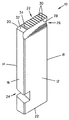
- the drawing is a perspective view of a thread cutting die in accordance with the present invention.
- the thread cutting die designated generally by the numeral 10 is formed from a bar of high speed steel which has a Rockwell C hardness of Rc 58 to 68.
- Die 10 has a pair of spaced apart parallel side walls 12 and 14 and a pair of spaced apart parallel end walls 16 and 18 and, in the orientation shown in the drawing, has an upper end 20 and a lower end 22 each extending between the pairs of side walls and end walls.
- Thread cutting teeth 22 are provided on upper end 20, preferably by grinding, and extend in the direction between side walls 12 and 14, whereby the teeth are adjacent to one another in the direction between end walls 16 and 18.
- Cutting die 10 is provided adjacent lower end 22 thereof with a cam recess 24 which, as is well known and shown in the aforementioned patent to Hayes. et al. for example, facilitates radial displacement of the cutting die relative to a die head during operation of a threading machine. More particularly, as will be seen from the foregoing patent, a cam supported on the die head for rotation relative thereto engages in the threading die cam recess, whereby the die is reciprocated in response to rotation of the cam in opposite directions relative to the die head. As is further well known in connection with such thread cutting dies, the cutting end thereof is provided with an arcuate undercut 26 which is shown in side wall 12 and extends between end wall 16 and 18.
- Undercut 26 intersects the corresponding ends of cutting teeth 22 to provide lip 28 therewith which defines the leading ends of teeth 22 with respect to the direction of thread cutting.
- adjacent ones of the cutting teeth 22 have planar teeth faces 30 diverging relative to one another in the direction outwardly of end 20 of the die.
- the tooth grinding process provides a profile which includes outer end faces 32 and 34 extending from end wall 16 toward end wall 18 of the cutting die.
- high speed steels for thread cutting dies or chasers of the foregoing character generally have a hardness of Rc 58 to 68 and are used, without more, in connection with the cutting of threads on most pipe and rod metals.
- Rc 58 to 68 a hardness of Rc 58 to 68
- improved cutting performance and extended life for the cutting dies is realized by coating the dies with an ultra hard protective coating material such as titanium nitride.
- the coating which can be of other ultra hard materials such as titanium aluminum nitride, titanium zirconium nitride and titanium vanadium nitride, for example, can be applied by any one of a number of known sputter deposition processes such as dc and rf diode sputtering, dc and rf triode sputtering, magnetron and unbalanced magnitron sputtering.
- the coating process can cover the thread cutting die in its entirety with the exception, perhaps, of bottom end 22 and, in such cases, extends over the entire chaser tooth form and shank and, accordingly, covers tooth faces 30 and end faces 32 and 34 as well as undercut 26, side walls 12 and 14 and end walls 16 and 18.
- the coating can be applied so as to exclude coating of the faces 30 of the teeth.
- Titanium nitride has a hardness of Rc 80 to 85 and, preferably, the coating has a thickness of from 3.5 to 6 microns.
- Such an ultra hard protective coating advantageously resists scratching, wearing and corrosion, thus prolonging tool life and providing improved performance over non-coated high speed steel dies.
- the coating, which heretofore was intentionally applied to faces 30 of the teeth is not removed as a result of using the cutting dies.
Landscapes
- Engineering & Computer Science (AREA)
- Mechanical Engineering (AREA)
- Cutting Tools, Boring Holders, And Turrets (AREA)
- Physical Vapour Deposition (AREA)
- Chemical Vapour Deposition (AREA)
- Gear Processing (AREA)
- Turning (AREA)
Applications Claiming Priority (2)
| Application Number | Priority Date | Filing Date | Title |
|---|---|---|---|
| US09/040,141 US5890852A (en) | 1998-03-17 | 1998-03-17 | Thread cutting die and method of manufacturing same |
| US40141 | 1998-03-17 |
Publications (2)
| Publication Number | Publication Date |
|---|---|
| EP0943386A2 true EP0943386A2 (de) | 1999-09-22 |
| EP0943386A3 EP0943386A3 (de) | 2000-07-19 |
Family
ID=21909348
Family Applications (1)
| Application Number | Title | Priority Date | Filing Date |
|---|---|---|---|
| EP98630066A Withdrawn EP0943386A3 (de) | 1998-03-17 | 1998-11-06 | Gewindeschneidwerkzeug und dessen Fertigungsmethode |
Country Status (6)
| Country | Link |
|---|---|
| US (1) | US5890852A (de) |
| EP (1) | EP0943386A3 (de) |
| JP (1) | JP3308220B2 (de) |
| CN (1) | CN1082410C (de) |
| CA (1) | CA2245302C (de) |
| TW (1) | TW417525U (de) |
Families Citing this family (29)
| Publication number | Priority date | Publication date | Assignee | Title |
|---|---|---|---|---|
| US6314778B1 (en) * | 1998-03-18 | 2001-11-13 | Mitsubishi Denki Kabushiki Kaisha | Rolling die and surface processing method for rolling die |
| JP2002166326A (ja) * | 2000-12-01 | 2002-06-11 | Kinichi Miyagawa | 管用ねじ切り工具、及び、その管用ねじ切り工具に使用されるチップ |
| EP1553968A4 (de) * | 2002-10-03 | 2009-06-24 | Northfield Lab | Verfahren zur behandlung von patienten mit massivem blutverlust |
| US7135553B2 (en) * | 2003-01-29 | 2006-11-14 | Northfield Laboratories, Inc. | Polymerized hemoglobin solutions having reduced amounts of tetramer and method for preparing |
| US6957933B2 (en) * | 2003-05-30 | 2005-10-25 | Siderca S.A.I.C. | Threading insert with cooling channels |
| US20060024140A1 (en) * | 2004-07-30 | 2006-02-02 | Wolff Edward C | Removable tap chasers and tap systems including the same |
| US7513320B2 (en) * | 2004-12-16 | 2009-04-07 | Tdy Industries, Inc. | Cemented carbide inserts for earth-boring bits |
| US7520698B2 (en) * | 2004-12-20 | 2009-04-21 | Gleason Cutting Tools Corporation | Cutting tool for gears and other toothed articles |
| US8637127B2 (en) | 2005-06-27 | 2014-01-28 | Kennametal Inc. | Composite article with coolant channels and tool fabrication method |
| US7687156B2 (en) | 2005-08-18 | 2010-03-30 | Tdy Industries, Inc. | Composite cutting inserts and methods of making the same |
| RU2432445C2 (ru) | 2006-04-27 | 2011-10-27 | Ти Ди Уай Индастриз, Инк. | Модульное буровое долото с неподвижными режущими элементами, корпус данного модульного бурового долота и способы их изготовления |
| EP2078101A2 (de) | 2006-10-25 | 2009-07-15 | TDY Industries, Inc. | Artikel mit erhöhter widerstandsfähigkeit gegenüber thermischem cracken |
| US7846551B2 (en) | 2007-03-16 | 2010-12-07 | Tdy Industries, Inc. | Composite articles |
| TW200944665A (en) * | 2008-04-18 | 2009-11-01 | Feng Yi Steel Co Ltd | Method for manufacturing screw element of titanium alloy and product thereof |
| EP2653580B1 (de) | 2008-06-02 | 2014-08-20 | Kennametal Inc. | Zementierte carbidmetallische Legierungsverbindungen |
| US8790439B2 (en) | 2008-06-02 | 2014-07-29 | Kennametal Inc. | Composite sintered powder metal articles |
| US8322465B2 (en) * | 2008-08-22 | 2012-12-04 | TDY Industries, LLC | Earth-boring bit parts including hybrid cemented carbides and methods of making the same |
| US8025112B2 (en) | 2008-08-22 | 2011-09-27 | Tdy Industries, Inc. | Earth-boring bits and other parts including cemented carbide |
| US8272816B2 (en) | 2009-05-12 | 2012-09-25 | TDY Industries, LLC | Composite cemented carbide rotary cutting tools and rotary cutting tool blanks |
| US8308096B2 (en) | 2009-07-14 | 2012-11-13 | TDY Industries, LLC | Reinforced roll and method of making same |
| US9643236B2 (en) | 2009-11-11 | 2017-05-09 | Landis Solutions Llc | Thread rolling die and method of making same |
| EP2420340B1 (de) * | 2010-08-20 | 2014-04-16 | VARGUS Ltd. | Gewindefrässchneideinsatz und Gewindefräser |
| US8800848B2 (en) | 2011-08-31 | 2014-08-12 | Kennametal Inc. | Methods of forming wear resistant layers on metallic surfaces |
| US9016406B2 (en) | 2011-09-22 | 2015-04-28 | Kennametal Inc. | Cutting inserts for earth-boring bits |
| CN103464796B (zh) * | 2013-09-06 | 2016-03-30 | 成都工具研究所有限公司 | 复杂成型梳齿刀具 |
| US12138702B2 (en) | 2019-11-01 | 2024-11-12 | Milwaukee Electric Tool Corporation | Portable pipe threader |
| US12109623B2 (en) | 2019-11-01 | 2024-10-08 | Milwaukee Electric Tool Corporation | Portable pipe threader |
| US12390870B2 (en) | 2021-03-31 | 2025-08-19 | Milwaukee Electric Tool Corporation | Lubrication system for portable pipe threader |
| USD1087188S1 (en) * | 2022-10-19 | 2025-08-05 | Milwaukee Electric Tool Corporation | Pipe threading die |
Family Cites Families (11)
| Publication number | Priority date | Publication date | Assignee | Title |
|---|---|---|---|---|
| US2004333A (en) * | 1934-03-28 | 1935-06-11 | Oster Mfg Co | Chaser holder |
| US2537818A (en) * | 1946-07-08 | 1951-01-09 | William H Evans | Reamer segment and method of producing same |
| US4266449A (en) * | 1978-04-11 | 1981-05-12 | Bielby Robert A | Method for making a cutting tool |
| JPS55150941A (en) * | 1979-05-09 | 1980-11-25 | Mitsubishi Metal Corp | Cutting tool of coated sintered hard alloy |
| JPS6044203A (ja) * | 1983-08-22 | 1985-03-09 | Sumitomo Electric Ind Ltd | 被覆超硬合金工具 |
| JPS60172403A (ja) * | 1984-02-17 | 1985-09-05 | Nippon Kokan Kk <Nkk> | 被覆超硬合金チエザ− |
| JPS60197317A (ja) * | 1984-03-15 | 1985-10-05 | Sumitomo Metal Ind Ltd | 高合金油井管のねじ切削方法 |
| US4708542A (en) * | 1985-04-19 | 1987-11-24 | Greenfield Industries, Inc. | Threading tap |
| US4813260A (en) * | 1987-04-27 | 1989-03-21 | Clevite Industries Inc. | Multipurpose tube working tool |
| JPH0639011B2 (ja) * | 1987-07-23 | 1994-05-25 | オ−エスジ−株式会社 | ねじ切りダイス |
| SE505742C2 (sv) * | 1993-09-07 | 1997-10-06 | Sandvik Ab | Gängtapp |
-
1998
- 1998-03-17 US US09/040,141 patent/US5890852A/en not_active Expired - Fee Related
- 1998-09-18 CA CA002245302A patent/CA2245302C/en not_active Expired - Fee Related
- 1998-11-02 JP JP31166298A patent/JP3308220B2/ja not_active Expired - Fee Related
- 1998-11-06 TW TW088216940U patent/TW417525U/zh not_active IP Right Cessation
- 1998-11-06 EP EP98630066A patent/EP0943386A3/de not_active Withdrawn
- 1998-11-17 CN CN98122402A patent/CN1082410C/zh not_active Expired - Fee Related
Also Published As
| Publication number | Publication date |
|---|---|
| US5890852A (en) | 1999-04-06 |
| JPH11262818A (ja) | 1999-09-28 |
| TW417525U (en) | 2001-01-01 |
| CN1229017A (zh) | 1999-09-22 |
| CA2245302C (en) | 2002-04-30 |
| EP0943386A3 (de) | 2000-07-19 |
| CN1082410C (zh) | 2002-04-10 |
| CA2245302A1 (en) | 1999-04-06 |
| JP3308220B2 (ja) | 2002-07-29 |
Similar Documents
| Publication | Publication Date | Title |
|---|---|---|
| US5890852A (en) | Thread cutting die and method of manufacturing same | |
| US6742968B1 (en) | Milling cutter | |
| JP4874911B2 (ja) | 長い有効寿命を有するコーティング工具 | |
| RU2409454C2 (ru) | Концевая фреза для орбитального фрезерования | |
| CN1089649C (zh) | 精确切削面的制造方法 | |
| CN103370158B (zh) | 用于在工件中生产螺纹的螺纹产生刀具 | |
| CN104582895B (zh) | 用于在工件中产生螺纹的方法和刀具 | |
| US6257810B1 (en) | Milling tool for thread-milling and boring of high-strength workpieces | |
| EP0767024A1 (de) | Gewindebohrer | |
| SE505742C2 (sv) | Gängtapp | |
| JPH11502775A (ja) | 切削工具 | |
| US20060121995A1 (en) | Tool and method for producing a thread in a tool | |
| EP2152459B1 (de) | Werkzeug für verbesserten chip-fluss | |
| JPS62188616A (ja) | フライス | |
| CN108080884B (zh) | 具有敲击面的开槽工具 | |
| JP2001071209A (ja) | ボールエンドミル | |
| US20060133901A1 (en) | Cutting tool for gears and other toothed articles | |
| JP2000052127A (ja) | エンドミル | |
| JPH09192930A (ja) | ねじ切りフライス | |
| JP2001239425A (ja) | ブローチ及びブローチ加工法 | |
| CN106238793A (zh) | 一种工艺凸台用立铣刀 | |
| EP4331748A1 (de) | Einsatz zum stangenschälen | |
| JP2514519Y2 (ja) | インターナルヘリカルブローチ | |
| CN206028836U (zh) | 一种工艺凸台用立铣刀 | |
| JP3005741U (ja) | 高硬度材用ハンドタップ |
Legal Events
| Date | Code | Title | Description |
|---|---|---|---|
| PUAI | Public reference made under article 153(3) epc to a published international application that has entered the european phase |
Free format text: ORIGINAL CODE: 0009012 |
|
| AK | Designated contracting states |
Kind code of ref document: A2 Designated state(s): DE ES GB IT |
|
| AX | Request for extension of the european patent |
Free format text: AL;LT;LV;MK;RO;SI |
|
| PUAL | Search report despatched |
Free format text: ORIGINAL CODE: 0009013 |
|
| AK | Designated contracting states |
Kind code of ref document: A3 Designated state(s): AT BE CH CY DE DK ES FI FR GB GR IE IT LI LU MC NL PT SE |
|
| AX | Request for extension of the european patent |
Free format text: AL;LT;LV;MK;RO;SI |
|
| 17P | Request for examination filed |
Effective date: 20000830 |
|
| AKX | Designation fees paid |
Free format text: DE ES GB IT |
|
| 17Q | First examination report despatched |
Effective date: 20020905 |
|
| GRAP | Despatch of communication of intention to grant a patent |
Free format text: ORIGINAL CODE: EPIDOSNIGR1 |
|
| STAA | Information on the status of an ep patent application or granted ep patent |
Free format text: STATUS: THE APPLICATION IS DEEMED TO BE WITHDRAWN |
|
| 18D | Application deemed to be withdrawn |
Effective date: 20040414 |