EP0942287A2 - Sensorring und Verfahren zu seiner Herstellung - Google Patents
Sensorring und Verfahren zu seiner Herstellung Download PDFInfo
- Publication number
- EP0942287A2 EP0942287A2 EP98114085A EP98114085A EP0942287A2 EP 0942287 A2 EP0942287 A2 EP 0942287A2 EP 98114085 A EP98114085 A EP 98114085A EP 98114085 A EP98114085 A EP 98114085A EP 0942287 A2 EP0942287 A2 EP 0942287A2
- Authority
- EP
- European Patent Office
- Prior art keywords
- sensor ring
- cylindrical
- rotating element
- mold
- free end
- Prior art date
- Legal status (The legal status is an assumption and is not a legal conclusion. Google has not performed a legal analysis and makes no representation as to the accuracy of the status listed.)
- Granted
Links
Images


Classifications
-
- B—PERFORMING OPERATIONS; TRANSPORTING
- B21—MECHANICAL METAL-WORKING WITHOUT ESSENTIALLY REMOVING MATERIAL; PUNCHING METAL
- B21D—WORKING OR PROCESSING OF SHEET METAL OR METAL TUBES, RODS OR PROFILES WITHOUT ESSENTIALLY REMOVING MATERIAL; PUNCHING METAL
- B21D53/00—Making other particular articles
- B21D53/16—Making other particular articles rings, e.g. barrel hoops
- B21D53/18—Making other particular articles rings, e.g. barrel hoops of hollow or C-shaped cross-section, e.g. for curtains, for eyelets
-
- G—PHYSICS
- G01—MEASURING; TESTING
- G01P—MEASURING LINEAR OR ANGULAR SPEED, ACCELERATION, DECELERATION, OR SHOCK; INDICATING PRESENCE, ABSENCE, OR DIRECTION, OF MOVEMENT
- G01P1/00—Details of instruments
-
- G—PHYSICS
- G01—MEASURING; TESTING
- G01P—MEASURING LINEAR OR ANGULAR SPEED, ACCELERATION, DECELERATION, OR SHOCK; INDICATING PRESENCE, ABSENCE, OR DIRECTION, OF MOVEMENT
- G01P3/00—Measuring linear or angular speed; Measuring differences of linear or angular speeds
- G01P3/42—Devices characterised by the use of electric or magnetic means
- G01P3/44—Devices characterised by the use of electric or magnetic means for measuring angular speed
- G01P3/48—Devices characterised by the use of electric or magnetic means for measuring angular speed by measuring frequency of generated current or voltage
- G01P3/481—Devices characterised by the use of electric or magnetic means for measuring angular speed by measuring frequency of generated current or voltage of pulse signals
- G01P3/488—Devices characterised by the use of electric or magnetic means for measuring angular speed by measuring frequency of generated current or voltage of pulse signals delivered by variable reluctance detectors
-
- Y—GENERAL TAGGING OF NEW TECHNOLOGICAL DEVELOPMENTS; GENERAL TAGGING OF CROSS-SECTIONAL TECHNOLOGIES SPANNING OVER SEVERAL SECTIONS OF THE IPC; TECHNICAL SUBJECTS COVERED BY FORMER USPC CROSS-REFERENCE ART COLLECTIONS [XRACs] AND DIGESTS
- Y10—TECHNICAL SUBJECTS COVERED BY FORMER USPC
- Y10T—TECHNICAL SUBJECTS COVERED BY FORMER US CLASSIFICATION
- Y10T29/00—Metal working
- Y10T29/49—Method of mechanical manufacture
- Y10T29/49481—Wheel making
Definitions
- the present invention relates to a sensor ring used for detection of rotation of a rotating element and a method of manufacturing such a sensor ring.
- a sensor ring is employed to detect rotation of a rotating element such as an axle of an automobile.
- the sensor ring has a cylindrical body mounted on the rotating element, an annular member extending from the cylindrical body in a radial direction of the cylindrical body and a plurality of openings formed in the annular member. These openings are spaced from each other in the circumferential direction of the annular member at constant pitches. A tooth is defined between each two adjacent openings of the annular member.
- the sensor ring is mounted on the rotating element such as an automobile axle, and a proximity sensor is provided nearby. The proximity sensor detects the teeth of the sensor ring which rotate with the rotating axle. The sensor ring and the proximity sensor in combination detect the rotational speed of the rotating element.
- the sensor ring is generally press fitted over an outer periphery of a free end of the rotating element, and the free end of the rotating element has a stepwise portion in its outer periphery to receive the sensor ring.
- the stepwise portion at the free end portion of the rotating element has an axially extending cylindrical surface to engage with an inner diameter portion of the cylindrical body of the sensor ring and a radially extending annular stop surface to support one end face of the sensor ring.
- the sensor ring is press fitted over the free end of the rotating element in the axial direction of the rotating element until it contacts the stop surface.
- the sensor ring seats on the radial stop surface of the rotating element so that the sensor ring is accurately positioned in the axial direction of the rotating element.
- the cylindrical body of the sensor ring defines a center bore having a simple cylindrical surface to be fitted over the cylindrical surface of the stepwise free end portion of the rotating element.
- the axially extending cylindrical surface and radially extending stop surface of the stepwise free end portion of the rotating element are formed by machining, and connection between these two surfaces is defined by an arcuate surface formed by a round nose of a cutting tool.
- a radius of the round nose of the cutting tool is relatively large, i.e., if the connection surface between the axially extending surface and radially extending surface of the rotating element has a relatively large radius of curvature, the end face of the sensor ring cannot abut on the stop surface of the rotating element when the sensor ring is press fitted over the rotating element.
- positioning of the senor ring in the axial direction of the rotating element and posture of the sensor ring relative to the stop surface i.e., flatness of the sensor ring
- the end face of the sensor ring may be deformed upon collision against the stop surface of the rotating element if the pressing force to press fit the sensor ring over the rotating element is excessively great or if the press fitting operation is performed in an impacting way. This results in reduction of length of the sensor ring in the axial direction of the rotating element and causes instability in the axial position and horizontal posture of the sensor ring.
- the sensor ring In order to press fit the sensor ring on the rotating element in a desired manner, it is ideal that the sensor ring is made from a one piece material having high stiffness and rigidity so that the sensor ring does not deform during the press fitting operation.
- the sensor ring is manufactured by sintering or machining. However, these manufacturing processes are complicated and troublesome.
- a press molding process is employed. A metallic plate material is press molded to a one piece product, but any conventional press molding methods provide satisfactory products.
- the present invention was conceived to eliminate the above described problems.
- One object of the present invention is to provide a novel sensor ring which can always abut on the radial stop surface formed at the free end portion of the rotating element regardless of the size of connection curvature between the radial and horizontal surfaces of the free end portion of the rotating element and a manufacturing method of such a sensor ring.
- Another object of the present invention is to provide a novel sensor ring which does not deform when it is press fitted over the free end portion of the rotating element and a manufacturing method of such a sensor ring.
- Still another object of the present invention is to provide a novel sensor ring which is a one piece product manufactured from a plate material with high rigidity and a method of making the same.
- Yet another object of the present invention is to provide a novel sensor ring which can be manufactured with a relatively small pressing force and a manufacturing method for such a sensor ring.
- Still another object of the present invention is to provide a novel sensor ring which can suppress a manufacturing error and and a manufacturing method therefor.
- the flange portion of the sensor ring extends diagonally outward in a radial direction from the periphery of the cylindrical portion of the sensor ring and has a gradually increasing diameter, the flange portion can avoid (or does not contact) a connection curvature between the axial and radial surfaces of the free end portion of the rotating element during the press fitting operation. As a result, the free end of the flange portion of the sensor ring can always abut on the radial stop surface of the rotating element. Thus, it is possible to locate the sensor ring on the rotating element at a desired position with desired flatness.
- the flange portion of the sensor ring may have a chamfered inner surface to avoid the connection curvature between the axial and radial surfaces of the free end portion of the rotating element.
- the free end of the flange portion may have a planar area which is parallel to the stop surface of the rotating element so that the flange portion of the sensor ring plane-contacts the planar radial stop surface of the rotating element.
- the sensor ring may have an annular sensing portion extending radially outward from the other end periphery of the cylindrical portion and an outer ring portion extending axially toward the flange portion from the outer periphery of the sensing portion to partly surround the cylindrical portion.
- the sensor ring is a one piece product having the cylindrical portion, the flange portion, the sensing portion and the outer ring portion.
- a plurality of rectangular or square openings may be formed in the sensing portion at constant intervals in the circumferential direction of the sensor ring.
- Each of the openings may have a radially outer side which is furthest from the center of the sensor ring, a radially inner side which is closest to the center of the sensor ring, and two other sides connecting ends of the outer side with ends of the inner sides respectively.
- a radial position of the inner side of each opening may substantially be the same as that of the outer wall of the cylindrical portion of the sensor ring.
- the radial position of the outer side of the opening may substantially be the same as that of the inner wall of the ring portion.
- a method of manufacturing a sensor ring from a blank of single plate material the sensor ring blank including a cylindrical portion, a sensing portion extending radially outward from one end periphery of the cylindrical portion and an outer ring portion extending axially toward the other end periphery of the cylindrical portion from the outer periphery of the sensing portion to partly surround the cylindrical portion, characterized in that the blank is set on a lower metallic mold of the first mold unit with the sensing portion being directed downward (i.e., toward the lower mold) and the cylindrical portion being engaged with a nest plate provided on the lower mold, a presser mold is lowered toward the lower mold until it is received in a space defined by the cylindrical portion, sensing portion and outer ring portion so that the sensing portion is clamped between the presser mold and lower mold and the blank is held in position, a plurality of pierce punches are lowered toward the lower mold with downward movement of the pierce punches being guided by the
- the pierce punches may be arranged with twice the pitch of the openings of the sensing portion so that the openings of the sensing portion are formed by first and second piercing operations. Between the first and second piercing operations, the blank may be rotated by one pitch of the sensing portion openings.
- the lower mold of the first mold unit may have a plurality of bores (punch holes) to receive the pierce punches respectively.
- a second nest pin may be provided in the lower mold between predetermined two punch holes such that it is projectable from the upper surface of the lower mold. The nest pin may be pushed back and may not project during the first piercing operation. When the first piercing operation is finished and the blank is rotated by one pitch of the openings, the nest pin may project and fit in one of the pierced openings. Thus, positioning of the blank before the second piercing operation is accurately performed.
- Such a nest pin may be provided more than one. Recesses (or pin holes) for receiving the nest pins may be formed in the lower mold.
- Each of the nest pins may have a sharp free end.
- Each of the pin holes may have an oval cross section with its major axis extending in a radial direction of the sensor ring so that the nest pin holes are larger than the punch holes in the radial direction.
- Each of the pierce punches may have a rectangular or square cross section and the presser mold may have mating rectangular or square grooves to slidably engage with and guide the pierce punches.
- the upper mold punch of the second mold unit may have a lower smaller diameter portion to push down the first nest pin when the upper mold punch is lowered, an upper larger diameter portion for bending the projecting length of the cylindrical portion of the blank in a radially outward direction, and a C (chamfered) surface formed at connection between the smaller and larger diameter portions.
- the smaller diameter portion may be in slide contact with the inner wall of the cylindrical portion of the sensor ring blank when the upper mold punch is moved downward.
- the projecting length of the cylindrical portion may be determined to have a size such that the corner defined by a horizontal end face of the projecting length and the vertical inner wall of the cylindrical portion is collapsed by the lower surface of the large diameter portion of the upper mold punch.
- the movable mold may have a vertically cylindrical surface which is exposed to and surrounds the peripheral wall of the small diameter portion of the upper mold punch when the upper mold punch is lowered, a horizontal annular surface which is exposed to the annular lower surface of the large diameter portion of the upper mold punch outside the C surface and a tapered surface which is exposed to the C surface of the upper mold punch and connects the vertical surface with the horizontal surface.
- the tapered surface of the movable mold may be steeper than the C surface.
- the length of the tapered surface may be about a half of that of the C surface in the radial direction of the sensor ring and the height of the tapered surface may be more than that of the C surface.
- a sensor ring 1 is coaxially fitted over a hub 2 of an automobile axle.
- the hub 2 (or axle) is one example of a rotating element.
- the hub 2 has a generally cylindrical shape having a center line C.
- the hub 2 has a stepwise portion on its outer surface to form a cylindrical surface 3 and a stop surface 4.
- the cylindrical surface 3 has a particular diameter and a particular length in an axial direction of the automobile axle along the center line C.
- the stop surface 4 extends radially outward at right angle relative to the cylindrical surface 3.
- the stop surface 4 defines an annular planar surface.
- the cylindrical surface 3 and stop surface 4 are formed by machining at high accuracy. These surfaces are connected with each other by a curving surface (R surface) 5 having a certain radius which is determined by a nose radius of a cutting tool used to form this curving surface 5.
- the sensor ring 1 has a generally annular shape.
- the sensor ring 1 is mounted on the hub 2 from the top of Figure 1 as indicated by the unshaded arrow.
- the sensor ring 1 is press fitted over the cylindrical surface 3 of the hub 2 until it abuts on the stop surface 4. Relative position of the sensor ring 1 to the hub 2 is determined in this manner.
- the sensor ring 1 includes a cylindrical portion 6 to be press fitted over the cylindrical surface 3 of the hub 2 and a flange portion 7 bending diagonally radially outward from the lower end of the cylindrical portion 6. The flange portion 7 abuts on the stop surface 4 when the sensor ring 1 is mounted on the hub 2.
- the sensor ring 1 also includes a sensing portion 8 extending radially outward from the upper end of the cylindrical portion 6 and an outer ring portion 9 extending downward from the outer periphery of the sensing portion 8.
- the sensor ring 1 is a one piece product made from a metallic plate material having a predetermined thickness such as SPHC by pressing and bending. The method of making the sensor ring 1 will be described later in detail.
- a proximity sensor 96 such as a magnetic sensor is provided near the sensor ring 1 to spacedly face the sensing portion 8 of the sensor ring 1.
- the proximity sensor 96 detects rotations of the sensor ring 1 (i.e., rotations of the rotating axle 2) and sends a particular signal to an indicator 98.
- the indicator 98 displays a rotational speed of the rotating axle 2.
- the sensing portion 8 is used for detection of rotations of the rotating element (hub 2).
- the sensing portion 8 has a plurality of rectangular openings 10 along its periphery at constant intervals (pitches).
- a web or tooth 11 is defined between each adjacent openings 10.
- the proximity sensor 96 ( Figure 1) detects the rotating webs 11 to determine the rotational speed of the hub 2.
- each of the rectangular openings 10 has an inner side (right side in the drawing) 12 which substantially overlaps the outer wall 13 of the cylindrical portion 6 when viewed from the above (best seen in Figure 3B) and an outer side (left side in the drawing) 14 which substantially overlaps the inner wall 15 of the outer ring portion 9.
- the width Wr of each rectangular opening 10 is substantially equal to the distance between the outer wall 13 of the cylindrical portion 6 and the inner wall 15 of the outer ring portion 9, and the radial positional difference Wr1 between the inner side 12 of the opening 10 and the outer wall 13 of the cylindrical portion 6 and the radial positional difference Wr2 between the outer side 14 of the opening 10 and the inner wall 15 of the outer ring portion 9 are both minute (less than 0.2 mm in this particular embodiment).
- P indicates a pitch of the rectangular openings 10.
- Figure 3B illustrates the vertical cross section of the outer ring portion 9, opening 10 and the cylindrical portion 6.
- the opening 10 having the width Wr which is substantially equal to the spacing between the outer wall 13 of the cylindrical portion 6 and the inner wall 15 of the outer ring portion 9 was difficult according to known methods. However, it is made possible by employing a novel and unique method which the inventors conceived (will be described later). Since there remains a solid part next to the rectangular opening 10 in both the radially outward and inward directions, rigidity is improved. In the illustrated embodiment, the rectangular opening 10 has the larger width Wr in the radial direction than the width Wh in the circumferential direction.
- the ratio of the circumferential width Ws of the web 11 to the circumferential width Wh of the rectangular opening 10 can be reduced to 0.75 or less.
- the webs or teeth 11 would project radially outward from the cylindrical portion 6 like a comb and rigidity of the sensing portion 8 would considerably be degraded.
- the sensor ring 1 has the outer ring portion 9 so that the webs or teeth 11 are connected with each other and the sensing portion 8 has sufficient rigidity.
- the sensing portion 8 defines a planar surface at high accuracy as a whole.
- the outer ring portion 9 is considerably shorter than the cylindrical portion 6 in the axial direction of the hub 2.
- the flange portion 7 extends diagonally downward at an obtuse angle from the cylindrical portion 6 (obtuse angle as measured from the outer wall of the cylindrical portion 6).
- the flange portion 7 avoids the curving surface 5 of the hub 2 and contacts the stop surface 4 at a position radially outward of the curving surface 5 of the hub 2.
- that part of the flange portion 7 which abuts on the stop surface 4 has an annular planar surface 16. This surface 16 has a small width in a radial direction of the sensor ring 1.
- the inner peripheral wall 17 of the flange portion 7 is made by pressing (press molding) (will be described later) and defines a chamfer (C surface). In cross section, the inner peripheral wall 17 extends diagonally straight in a radially outward direction. Dimensions of the inner peripheral wall 17 (C1 and C2 in Figure 12) are determined such that the inner peripheral wall 17 can avoid the curving surface 5 of the hub 2.
- the sensor ring 1 Since the above described flange portion 7 is provided, the sensor ring 1 does not contact the curving surface 5 of the rotating element 2 and can reach the stop surface 4 reliably in the sensor ring mounting operation. Consequently, it is possible to accurately position the sensor ring 1 relative to the hub 2 in the axial direction and to insure flatness (horizontal posture) of the sensing portion 8 relative to the stop surface 4 of the hub 2 or relative to the proximity sensor 96.
- the flange portion 7 also raises rigidity of the entire sensor ring 1. Therefore, the sensing portion 8 does not deform during the press fitting operation.
- the flange portion 7 Since the flange portion 7 has the planar surface 16 at its free end face, it has a relatively large contact area to the stop surface 4 as compared with the flange portion having a sharp or rounded free end.
- the planar surface 16 disperses a shock upon abutting onto the stop surface 4 and further prevents deformation of the sensor ring 1.
- the sensing portion 8 can be located in a desired position in the axial direction and can extend at right angle relative to the center line C of the hub 2 more accurately. Precise parallelism between the planar surface 16 and the sensing portion 8 or flatness of the planar surface 16 relative to the sensing portion 8 is easily realized by a pressing method which will be described later.
- the sensor ring 1 is a one piece product made from a single plate material by a manufacturing method which will be described later.
- the sensor ring 1 is lightweight but has high rigidity. Accordingly, it is feasible to prevent deformation of the sensor ring 1 during the press fitting process and during in use.
- a plate material 18 is molded to a blank 19 which has the cylindrical portion 6, the sensing portion 8 and the outer ring portion 9.
- the first piercing step (49) is carried out to form a half of (or every other) rectangular openings 10a in the sensing portion 8.
- the second piercing step (50) is carried out to form the remainder of the rectangular openings 10b between the openings 10a as illustrated in Figure 4C.
- the lower end periphery of the cylindrical portion 6 is bent radially outward diagonally to form the flange portion 7 as illustrated in Figure 4D.
- the sensor ring 1 is accordingly manufactured.
- the plate material 18 which has a round shape if viewed from the above.
- the plate material 18 has an intermediate thickness (e.g., about 1 to 4 mm in this embodiment).
- This plate material 18 undergoes a drawing process to have a flange 22, a cylindrical body 20 and a bottom 21 as shown in Figure 5B.
- the bottom 21 is punched by piercing and the flange 22 is bent over downward like an inverted rounded U (or J) as depicted in Figure 5C.
- the material 18 undergoes the burring process and the ironing process to form the cylindrical portion 6 having a linear cross section as illustrated in Figure 5D.
- the inverted rounded U flange 22 is shaped to an inverted angled U as illustrated in Figure 5E.
- the sensing portion 8 and the outer ring portion 9 are formed.
- the blank 19 is prepared.
- the sensing portion 8 and the outer ring portion 9 are molded with high precision. Particularly, their inner and outer diameters are important. Further, in order to suppress the molding load needed in forming the flange portion 7 of the sensor ring 1, the blank is molded to have a precise height.
- the blank 19 is now set on the first mold unit 23 to carry out the first and second piercing processes (49 and 50 in Figures 4B and 4C).
- the first mold unit 23 includes a lower mold 24 which is a stationary mold and an upper mold 25 which is a liftable mold.
- the lower mold 24 has a die 26 secured on an upper surface of the lower mold, and the die 26 has a nest plate 27 secured on an upper surface of the die 26.
- the upper mold 25 has a punch holder 28 on its lower surface.
- a plurality of pierce punches 29 each extending vertically downward are firmly supported from the punch holder 28.
- the pierce punches 29 are arranged in a circumferential direction at predetermined intervals so that the punches 29 can create the rectangular openings 10 in the sensing portion of the sensor ring 1 at the predetermined intervals.
- the upper mold 25 also has guide posts 30 and bolts 65 extending vertically downward therefrom.
- the guide posts 30 and bolts 65 are spacedly arranged in the circumferential direction of the upper mold 25 in a predetermined manner (e.g., alternately).
- a presser mold 31 is supported by the guide posts 30 and bolts 65 such that it can move up and down.
- the blank 19 is placed on the die 26 with the sensing portion 8 being directed downward.
- the cylindrical portion 6 fits over the nest plate 27 so that centering of the blank 19 is appropriately carried out.
- the number of the pierce punches 29 is half of the required rectangular openings 10 and the pierce punch pitch in the circumferential direction is twice the rectangular opening pitch P ( Figure 3). Accordingly, the pierce punches 29 form every other rectangular openings 10 (10a and 10b) in one operation.
- Each of the pierce punches 29 has a rectangular cross section which coincides with the shape of the rectangular opening 10.
- the die 26 has punch holes 32 of a cross section similar to the pierce punch 29 to receive the pierce punches 29 penetrating through the blank 19.
- the number of the punch holes 32 is equal to that of the pierce punches 29.
- the punch holes 32 communicate with chute holes 33 formed in the lower mold 24. A refuse generated upon punching the blank 19 falls in the holes 32 and 33 and is discharged.
- the guide posts 30 are simple pins attached to the lower surface of the upper mold 25.
- the guide bolts 65 have threaded portions 34 and are secured to the upper mold 25 by threaded engagement with the upper mold 25.
- a coil spring 35 is wound around each guide bolt 65 to bias the presser mold 31 downward.
- the presser mold 31 are clamped between heads 36 of the guide bolts 65 and the associated coil springs 35, and are generally moved together with the upper mold 25.
- the presser mold 31 collides with the blank during downward movement of the upper mold 25, the presser mold 31 cannot move downward further.
- the upper mold 25 can move further downward due to compression of the coil springs 35.
- a repulsive force generated by the compressed coil springs 35 at this point causes the sensing portion 8 to firmly contact the die 26. After punching, this repulsive force from the springs 35 also serves as a stripping force to facilitate separation of the pierce punches 29 from the sensing portion 8.
- the presser mold 31 has a plurality of finger-like extensions 37 projecting downward from the inner peripheral wall thereof. As best illustrated in Figure 7, these extensions 37 engage in a space 38 defined by the cylindrical portion 6, sensing portion 8 and outer ring portion 9 to hold the sensing portion 8 on the die 26 from the above when the presser mold 31 is lowered toward the lower mold 24.
- An lower inner wall 39 and lower outer wall 40 of each extension 37, the outer wall 13 of the cylindrical portion 6 and the inner wall 15 of the outer ring portion 9 are precisely molded such that all of them can slide relative to each other.
- the outer wall 40 of each extension 37 has a cutout portion 42 to avoid intervening with the outer ring portion 9.
- a first nest pin 43 is provided in the die 26 such that it is projectable from the upper surface of the die 26.
- the first nest pin 43 is received in a pin hole 44 formed in the die 26 and moves up and down.
- the pin hole 44 guides this movement of the first nest pin 43.
- the first nest pin 43 projects from the die 26 when the second piercing process is conducted ( Figure 4C) but retracted or pushed down in the pin hole 44 when the first piercing process is conducted ( Figure 4B).
- a spring 45 is located in the pin hole 44 to bias the first nest pin 43 upward. In a normal situation, in addition to during the second piercing process, therefore, the first nest pin 43 projects from the upper face of the die 26.
- the top of the first nest pin 43 is a sharp free end like a roof.
- the radial position of the pin hole 44 is the same as the punch holes 32.
- the pin hole 44 is located at a midway between particular two adjacent punch holes 32. In other words, the pin hole 44 is spaced from the nearest punch hole 32 by one pitch P in the circumferential direction.
- the pin hole 44 is an elongated oval hole as compared with the punch hole 32 with its major axis extending in a radial direction of the die 26 (longer than the punch hole 32 in the radial direction of the die 26), and has rounded ends at inner and outer radial ends if viewed from the above.
- first nest pin 43 and one pin hole 44 are illustrated in Figure 8, a plurality of pairs of nest pin and holes may be provided at predetermined intervals in the circumferential direction of the die 26.
- the width of the first nest pin 43 in the circumferential direction of the die 26 is slightly smaller than that of the pierce punch 29.
- each of the grooves 46 has three vertical surfaces to slidably guide the associated pierce punch 29 as understood from Figure 7.
- One surface 48 of the three vertical surfaces of each groove 46 is directed radially inward and takes the substantially same radial position as the inner wall 15 of the outer ring portion 9 so that it cooperates with the outer wall 13 of the cylindrical portion 6 to accurately guide the associated pierce punch 29.
- the first piercing process using the first mold set 23 will be performed in the following manner.
- the blank 19 is placed on the die 26 with the sensing portion 8 being directed downward.
- the first nest pins 43 are pressed downward by the sensing portion 8 so that they are completely received in the associated pin holes 44.
- the upper mold 25 is lowered together with the presser mold 31.
- the fingers 37 of the presser mold 31 engage in the space 38 between the cylindrical portion 6, sensing portion 8 and outer ring portion 9 of the blank 19, and holds the sensing portion 8 against the die 26 from the above. Consequently, the blank 19 is held in the three directions.
- the upper mold 25 is moved upward.
- the presser mold 31 is pressed downward against the die 26 by the repulsive force exerted by the coil springs 35 so that the sensing portion 8 is held on the die 26 while the pierce punches 29 are being lifted up from the rectangular openings 10.
- the fingers 37 of the presser mold 31 leave the space 38 and then the blank 19 is pushed up by the first nest pins 43.
- the first nest pins 43 project from the upper surface of the die 26 in this situation.
- the blank 19 after the first piercing process 49 "floats" from the die 26 with the cylindrical portion 6 being still fitted over the nest plate 27.
- the blank 19 (49) is rotated by one pitch P in the circumferential direction so that the projecting first nest pins 43 fit in the rectangular openings 10 just pierced and the blank 19 (49) is caused to seat on the die 26 again. In this manner, the blank 19 (49) is easily set on the die 26. Further, the blank 19 (49) is accurately positioned in the circumferential direction. Since the free end of each of the first nest pins 43 is sharp pointed, the first nest pin 43 fits in the associated opening 10 easily and reliably.
- the second piercing process 50 ( Figure 4C) is carried out.
- the upper mold 25 is moved down together with the punch pierce punches 29 to form the remaining half of the rectangular openings 10 (10b).
- the first nest pins 43 project through the blank 19 and are received in the grooves 47 of the presser mold 31.
- the upper mold 25 is lifted up and the blank 19 (50) is picked up. The entire piercing process is completed in this manner.
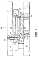
- the blank 50 is then set on the second mold unit 51 to perform the bending process to the cylindrical portion 6.
- the right side of the center line Cx illustrates when an upper mold 53 is lifted up and the left side illustrates when the upper mold 53 is moved down.
- the second mold unit 51 includes a stationary lower mold 52 and the elevatable upper mold 53.
- the lower mold 52 has a lower mold riser 54 fixed on the upper surface of the lower mold 52, and the lower mold riser 54 has a punch 55 fixed on the upper surface of the lower mold riser.
- the upper mold 53 coaxially has an upper mold punch 56 mounted on the lower face thereof, and a ring-shaped resilient member 57 is also provided on the lower face of the upper mold 53 around the punch 56.
- the lower mold 52 also has a second nest pin 58 on its upper face such that the second nest pin 58 can move up and down.
- a movable mold 59 is also provided on the upper face of the lower mold 52 such that the mold 59 can move in a radial direction.
- the lower mold riser 54 has a stepwise upper surface to define a cylindrical projecting part 60 around its center.
- the fixed punch 55 is a ring-shaped member with its outer diameter being the same diameter as the projecting part 60.
- the punch 55 is coaxially secured on the projecting part 60.
- the punch 55 has an L-shaped cross section with its shorter side being directed radially inward in order to stabilize the seating of the punch 55 on the mold riser 54.
- the blank 50 with the sensing portion 8 being directed downward is placed on the top of the longer side of "L" of the punch 55.
- the punch 55 has a radial thickness which is substantially equal to the radial length of the sensing portion 8 of the blank 50.
- the second nest pin 58 is in slidable contact with the inner wall 61 of the fixed punch 55. In the normal condition, as illustrated in the right half of Figure 10, the second nest pin 58 is maintained in a posture projecting from the fixed punch 55.
- the second nest pin 58 has a shaft 62 extending vertically downward from the lower face thereof, and the pin shaft 62 extends through a center bore 63 of the lower mold riser 54 and a coaxial center bore 63' of the lower mold riser 52.
- the pin shaft 62 is biased upward by a biasing means (not shown) but an upper positional limitation of the pin shaft 62 is regulated by a stop means (not shown) . Therefore, the second nest pin 58 is maintained at the illustrated position during the normal condition although an upward force is acting on the second nest pin 58.
- the movable mold 59 has a cylindrical shape surrounding the fixed punch 55 and is comprised of a plurality of segments divided in the circumferential direction (two semicircular segments in this particular embodiment). The segments can move radially.
- a cylinder unit (actuator unit) 64 is attached to an outer wall of each mold segment 59 to relocate the associated mold segment 59 in the radial direction.
- the mold segments 59 move horizontally on a plane outside the projecting part 60 of the lower mold riser 54.
- a slider 66 is attached to the upper surface of the lower mold riser 54 outside the projecting part 60 and a mating slider 67 is attached to the lower surface of the movable mold 59.
- the movable mold 59 has an upper extension 68 projecting radially inward from an inner upper wall thereof.
- the movable mold segments 50 are moved radially outward beforehand.
- the blank 50 is placed on the fixed punch 55 with the sensing portion 8 directed downward.
- the cylindrical portion 6 of the blank 50 fits over the second nest pin 58 so that centering of the blank 50 is appropriately performed.
- the movable mold segments 59 are moved radially inward as illustrated in Figure 10 until the radial extensions 68 of the movable mold segments 59 hold the cylindrical portion 6 from the outer lateral side.
- the radial extensions 68 have a height not to intervene with the outer ring portion 9 of the blank during this radially inward movement.
- the resilient member 57 is made from a resilient material such as urethane rubber.
- the resilient member 57 is sandwiched by the upper mold 53 and a ring plate 75 and secured to the upper mold 53 by bolts 76.
- Each of the bolts 76 has a threaded part 77 and the threaded part 77 is buried in the upper mold 53 such that the resilient member 57 can have a natural length in the normal condition as shown in the right half of the drawing.
- the upper mold punch 56 has a stepwise cylindrical shape comprised of an upper large diameter part 69 and a lower small diameter part 70.
- the small diameter part 70 has an outer diameter substantially equal to the inner diameter of the cylindrical portion 6 of the blank 50 so that the small diameter part 70 slidably contacts the inner wall 71 of the cylindrical portion 6 of the blank 50.
- the large diameter part 69 defines a step surface 72, which is a lower surface of the large diameter part 69, the small diameter part 70 defines an outer peripheral wall 73, and a C surface 74 connects the surface 72 with the surface 73.
- the punch 56 has the above described construction in order to form the C surface 17 of the sensor ring 1 ( Figures 1 and 2).
- Figure 12 illustrates the detail of the C surface 74 of the punch 56.
- the radial extension 68 of the movable mold 59 has an inclined surface 81 connecting its horizontal upper surface 80 with its vertical inner wall 79.
- the C surface 74 of the punch 56 has a radial length C1 and a height C2.
- C1 C2 so that the C surface 74 extends at 45 degrees relative to the height direction of the punch 56 as well as the radial direction.
- the taper surface 81 of the movable mold 59 extends steep as compared with the C surface 74.
- the taper surface 81 has a radial width Wdr which is approximately a half of C1 of the C surface 74 and a height Wdh which is greater than C2 of the C surface 74.
- the reason why the taper surface 81 possess these dimensions will be described later.
- the gap between the outer wall 73 of the small diameter part 70 of the punch 56 and the inner wall 79 of the radial extension 68 of the movable mold 59 is equal to the thickness T of the cylindrical portion 6 of the sensor ring 1.
- the upper mold 53 is caused to descend as illustrated in the left half of Figure 10 so that the small diameter part 70 of the upper mold punch 56 fits in the cylindrical portion 6 of the blank 50.
- the lower end face of the small diameter part 70 is chamfered along its periphery so that the small diameter part 70 is easily and reliably inserted in the cylindrical portion 6.
- the outer wall 73 of the small diameter part 70 slides along the inner wall 71 of the cylindrical portion 6.
- the small diameter part 70 collides on the second nest pin 58 and pushes the second nest pin 58 downward out of the blank 50.
- the second nest pin 58 which maintains centering of the blank 50 is disengaged from the blank 50, the small diameter part 70 now fits in the cylindrical portion 6 so that off centering of the blank 50 is prevented.
- the upper free end of the cylindrical portion 6 is clamped between the C surface 74 and planar step surface 72 of the upper mold punch 56 and the taper surface 81 and planar upper surface 80 of the movable mold 59, and is bent radially outward in a diagonally upward direction in the drawing.
- the movable die 59 therefore also serves as a die. This bending process is continued until the second nest pin 58 abuts on the lower mold riser 54 (lower dead point). Upon completion of the bending process, the flange 7 of desired shape is formed. Accordingly, the sensor ring 1 is prepared.
- the upper mold 53 is lifted up and the movable molds 59 are slid radially outward for picking up of the product 1.
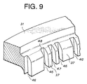
- Figures 11A, 11B and 11C illustrate different examples of bending process.
- Figure 11A depicts an example where the projecting length Hm of the cylindrical portion 6 is relatively large and the taper surface 81 has the same size and extends in the same direction as the C surface 74
- Figure 11B depicts an example where the projecting length Hm is relatively short and the same taper surface 81 as Figure 11A is employed
- Figure 11C depicts an example where the projection length Hm is relatively short and the taper surface 81 extends steeply as shown in Figure 12 (present invention).
- the illustrated embodiment therefore provides a desired sensor ring 1.
- first and second processes 49 and 50 Figure 4B and 4C
- the best inclined surface 81 is selected ( Figure 12)
- the manufacturing machine first mold unit 23, second mold unit 51 and associated components such as drive units
Landscapes
- Physics & Mathematics (AREA)
- General Physics & Mathematics (AREA)
- Engineering & Computer Science (AREA)
- Mechanical Engineering (AREA)
- Transmission And Conversion Of Sensor Element Output (AREA)
Applications Claiming Priority (2)
| Application Number | Priority Date | Filing Date | Title |
|---|---|---|---|
| JP10056771A JP2879042B1 (ja) | 1998-03-09 | 1998-03-09 | センサリング及びその製造方法 |
| JP5677198 | 1998-03-09 |
Publications (3)
| Publication Number | Publication Date |
|---|---|
| EP0942287A2 true EP0942287A2 (de) | 1999-09-15 |
| EP0942287A3 EP0942287A3 (de) | 2000-01-05 |
| EP0942287B1 EP0942287B1 (de) | 2004-05-06 |
Family
ID=13036749
Family Applications (1)
| Application Number | Title | Priority Date | Filing Date |
|---|---|---|---|
| EP98114085A Expired - Lifetime EP0942287B1 (de) | 1998-03-09 | 1998-07-28 | Sensorring und Verfahren zu seiner Herstellung |
Country Status (4)
| Country | Link |
|---|---|
| US (1) | US6392405B1 (de) |
| EP (1) | EP0942287B1 (de) |
| JP (1) | JP2879042B1 (de) |
| DE (1) | DE69823639T2 (de) |
Cited By (4)
| Publication number | Priority date | Publication date | Assignee | Title |
|---|---|---|---|---|
| EP1088751A3 (de) * | 1999-09-30 | 2003-05-02 | Honda Giken Kogyo Kabushiki Kaisha | Vorrichtung zur Erfassung der Radgeschwindigkeit für ein Fahrzeug |
| DE10205046A1 (de) * | 2002-02-07 | 2003-08-28 | Knorr Bremse Systeme | An einer Bremsscheibe oder Radnabe eines Kraftfahrzeuges einbaubares Polrad |
| WO2003098227A1 (en) * | 2002-05-14 | 2003-11-27 | The Timken Company | Speed sensor target wheel with improved retention capability |
| CN101956798A (zh) * | 2009-07-15 | 2011-01-26 | 加特可株式会社 | 带式无级变速器 |
Families Citing this family (19)
| Publication number | Priority date | Publication date | Assignee | Title |
|---|---|---|---|---|
| JP4450447B2 (ja) * | 1999-02-23 | 2010-04-14 | プレス工業株式会社 | センサリングのフランジ部加工方法 |
| US6693418B2 (en) | 2000-01-07 | 2004-02-17 | Bendix Commercial Vehicle Systems Llc | Magnetic wheel speed sensor having one-piece pole and magnetic flux concentrator |
| US6498475B2 (en) * | 2001-03-06 | 2002-12-24 | Delphi Technologies, Inc. | Performance sensor ring with reduced mass |
| KR20030020672A (ko) * | 2001-09-04 | 2003-03-10 | 한국델파이주식회사 | 스틸 파이프를 이용한 자동차 abs 브레이크용 센서링 |
| US20040140166A1 (en) * | 2003-01-21 | 2004-07-22 | Delphi Technologies Inc. | Integral rotor and tone wheel |
| BRPI0404360A (pt) * | 2004-10-07 | 2005-05-24 | Sabo Ind & Comercio Ltda | Anel sensibilizador de sensor |
| DE102004049355A1 (de) * | 2004-10-08 | 2006-04-13 | Knorr-Bremse Systeme für Nutzfahrzeuge GmbH | Verfahren zur Herstellung einer Polrad/Radnaben-Verbindung und deren Anordnung |
| JP4487851B2 (ja) * | 2005-05-20 | 2010-06-23 | 株式会社デンソー | 車両用回転検出装置の製造方法 |
| KR100750700B1 (ko) * | 2005-05-30 | 2007-08-22 | 주식회사 유성에프티 | 차량용 톤휠의 제조방법과 그 제조장치 및 그 제조방법으로 제조된 차량용 톤휠 |
| US20070176593A1 (en) * | 2006-01-31 | 2007-08-02 | Paul Fathauer | Transmission sensor with overmolding and method of manufacturing the same |
| JP4843699B2 (ja) * | 2009-07-15 | 2011-12-21 | ジヤトコ株式会社 | 自動変速機 |
| DE102017112075A1 (de) * | 2017-06-01 | 2018-12-06 | Knorr-Bremse Systeme für Nutzfahrzeuge GmbH | An einem drehbaren Bauteil eines Kraftfahrzeuges verdrehsicher gehaltenes Polrad |
| DE102017127407A1 (de) | 2017-11-21 | 2018-08-16 | Schaeffler Technologies AG & Co. KG | Nadellager mit einem Signalgeber |
| EP3856429A4 (de) * | 2018-09-27 | 2022-06-22 | Inno-Spin LLC | Mehrachsige walzformverfahren, systeme und produkte |
| KR102558323B1 (ko) | 2018-12-13 | 2023-07-20 | 다이아그노스 얼리, 인크. | 휘발성 유기 화합물 수집을 위한 디바이스, 방법 및 시스템 |
| US10829201B2 (en) * | 2019-03-20 | 2020-11-10 | Pratt & Whitney Canada Corp. | Blade angle position feedback system with extended markers |
| US11524741B2 (en) * | 2020-07-16 | 2022-12-13 | Shimano Inc. | Sensor wheel and disc brake apparatus |
| US20240060556A1 (en) * | 2021-02-22 | 2024-02-22 | Jatco Ltd | Sensor arrangement structure |
| US11725696B2 (en) * | 2021-05-17 | 2023-08-15 | Aktiebolaget Skf | Sensor bearing unit and associated assembly method |
Citations (2)
| Publication number | Priority date | Publication date | Assignee | Title |
|---|---|---|---|---|
| DE3702474A1 (de) * | 1986-02-05 | 1987-08-06 | Volkswagen Ag | Metallisches impulsrad fuer eine beruehrungslos arbeitende drehzahlmesseinrichtung |
| DE4230043A1 (de) * | 1992-09-08 | 1994-03-10 | Knorr Bremse Ag | Impulsring für ABS-überwachte Fahrzeugräder |
Family Cites Families (14)
| Publication number | Priority date | Publication date | Assignee | Title |
|---|---|---|---|---|
| US3626226A (en) | 1970-06-01 | 1971-12-07 | Bendix Corp | Wheel speed sensor for an adaptive braking system |
| US3916234A (en) | 1973-05-24 | 1975-10-28 | Wagner Electric Corp | Vehicle wheel speed sensor |
| US3890517A (en) | 1973-11-23 | 1975-06-17 | Kelsey Hayes Co | Wheel speed sensor |
| US4017756A (en) | 1975-08-18 | 1977-04-12 | Borg-Warner Corporation | Automatic sensor positioner |
| IN149928B (de) | 1977-07-22 | 1982-06-05 | Ransome Hoffmann Pollard | |
| US4171495A (en) | 1978-03-20 | 1979-10-16 | Eaton Corporation | Wheel speed sensor |
| JPS6154272A (ja) | 1984-08-24 | 1986-03-18 | 株式会社日立製作所 | 洗浄装置 |
| JPH0333012Y2 (de) | 1984-09-13 | 1991-07-12 | ||
| JPS61139472A (ja) | 1984-12-12 | 1986-06-26 | Tokyo Electric Co Ltd | プリンタ |
| JPS61163280A (ja) | 1985-01-10 | 1986-07-23 | Terumo Corp | プラズマ反応装置 |
| JPS6387514A (ja) | 1986-09-30 | 1988-04-18 | Toshiba Corp | 触媒燃焼器 |
| JPS63246677A (ja) | 1987-04-01 | 1988-10-13 | Nippon Seiko Kk | 軸受組立体 |
| US4795278B1 (en) | 1986-11-28 | 1992-11-03 | Nippon Seiko Kk | Bearing assembly |
| JPH01126419A (ja) | 1987-11-06 | 1989-05-18 | Nippon Seiko Kk | 軸受組立体 |
-
1998
- 1998-03-09 JP JP10056771A patent/JP2879042B1/ja not_active Expired - Lifetime
- 1998-04-30 US US09/070,349 patent/US6392405B1/en not_active Expired - Fee Related
- 1998-07-28 EP EP98114085A patent/EP0942287B1/de not_active Expired - Lifetime
- 1998-07-28 DE DE69823639T patent/DE69823639T2/de not_active Expired - Lifetime
Patent Citations (2)
| Publication number | Priority date | Publication date | Assignee | Title |
|---|---|---|---|---|
| DE3702474A1 (de) * | 1986-02-05 | 1987-08-06 | Volkswagen Ag | Metallisches impulsrad fuer eine beruehrungslos arbeitende drehzahlmesseinrichtung |
| DE4230043A1 (de) * | 1992-09-08 | 1994-03-10 | Knorr Bremse Ag | Impulsring für ABS-überwachte Fahrzeugräder |
Cited By (6)
| Publication number | Priority date | Publication date | Assignee | Title |
|---|---|---|---|---|
| EP1088751A3 (de) * | 1999-09-30 | 2003-05-02 | Honda Giken Kogyo Kabushiki Kaisha | Vorrichtung zur Erfassung der Radgeschwindigkeit für ein Fahrzeug |
| DE10205046A1 (de) * | 2002-02-07 | 2003-08-28 | Knorr Bremse Systeme | An einer Bremsscheibe oder Radnabe eines Kraftfahrzeuges einbaubares Polrad |
| WO2003098227A1 (en) * | 2002-05-14 | 2003-11-27 | The Timken Company | Speed sensor target wheel with improved retention capability |
| US6870363B2 (en) | 2002-05-14 | 2005-03-22 | The Timken Company | Speed sensor target wheel with improved retention capability |
| CN101956798A (zh) * | 2009-07-15 | 2011-01-26 | 加特可株式会社 | 带式无级变速器 |
| CN101956798B (zh) * | 2009-07-15 | 2016-01-20 | 加特可株式会社 | 带式无级变速器 |
Also Published As
| Publication number | Publication date |
|---|---|
| EP0942287B1 (de) | 2004-05-06 |
| DE69823639T2 (de) | 2005-04-07 |
| JP2879042B1 (ja) | 1999-04-05 |
| JPH11258255A (ja) | 1999-09-24 |
| DE69823639D1 (de) | 2004-06-09 |
| EP0942287A3 (de) | 2000-01-05 |
| US6392405B1 (en) | 2002-05-21 |
Similar Documents
| Publication | Publication Date | Title |
|---|---|---|
| EP0942287B1 (de) | Sensorring und Verfahren zu seiner Herstellung | |
| US8875555B2 (en) | Bossed disc-like member manufacturing method and bossed disc-like member manufacturing apparatus | |
| EP0049474B1 (de) | Schmiedegesenk zur Herstellung eines Werkstücks mit inneren, sich verjüngenden Nuten | |
| US8015708B2 (en) | Method and apparatus for manufacturing tonewheel for vehicles | |
| US4638538A (en) | Method of manufacturing wound bush bearing with notch-free flange and mold assembly for manufacturing the same | |
| US20080219611A1 (en) | Cage for Radial Needle Bearing, Method for Manufacturing the Same and Radial Needle Bearing | |
| EP0559178A1 (de) | Verfahren zum Verformen einer Metalldose zum Erhöhen seiner Formfestigkeit | |
| JP4814118B2 (ja) | 歯車成形方法及び装置 | |
| US20090235517A1 (en) | Progressive and transfer die stamping | |
| EP0759333A1 (de) | Verfahren zur Herstellung eines Bolzens | |
| JPH03268830A (ja) | ベアリング用締め付けナットのナット素材の製造方法 | |
| EP1462193B1 (de) | Verfahren und Vorrichtung zur Herstellung von geflanschten Gegenständen | |
| JP4450447B2 (ja) | センサリングのフランジ部加工方法 | |
| KR100872830B1 (ko) | 차량용 톤휠의 제조방법 및 장치 | |
| EP0584907A2 (de) | Vorrichtung zum Schmieden eines schrägverzahnten Zahnrades | |
| JPS6137012B2 (de) | ||
| KR100737285B1 (ko) | 차량용 톤휠의 제조방법 및 장치 | |
| JP3469275B2 (ja) | 歯車素形材の製造方法及び製造装置 | |
| EP2826571B1 (de) | Verfahren zur Herstellung einer Riemenscheibe für Kraftfahrzeuganwendungen | |
| JP3438497B2 (ja) | プレス型 | |
| CN115916427A (zh) | 工件制造装置 | |
| JPH10216893A (ja) | 管材のフランジ加工装置及びその方法 | |
| CN116323092A (zh) | 用于将辅助接合件插入到工件中的装置和方法和组件 | |
| EP1783883A1 (de) | Vorrichtung zum rasierschutz auf einem schwungrad und verfahren zum rasierschutz | |
| JPH09150234A (ja) | 歯付リングの成形方法及び成形型 |
Legal Events
| Date | Code | Title | Description |
|---|---|---|---|
| PUAI | Public reference made under article 153(3) epc to a published international application that has entered the european phase |
Free format text: ORIGINAL CODE: 0009012 |
|
| AK | Designated contracting states |
Kind code of ref document: A2 Designated state(s): DE FR SE |
|
| AX | Request for extension of the european patent |
Free format text: AL;LT;LV;MK;RO;SI |
|
| PUAL | Search report despatched |
Free format text: ORIGINAL CODE: 0009013 |
|
| AK | Designated contracting states |
Kind code of ref document: A3 Designated state(s): AT BE CH CY DE DK ES FI FR GB GR IE IT LI LU MC NL PT SE |
|
| AX | Request for extension of the european patent |
Free format text: AL;LT;LV;MK;RO;SI |
|
| 17P | Request for examination filed |
Effective date: 20000417 |
|
| AKX | Designation fees paid |
Free format text: DE FR SE |
|
| 17Q | First examination report despatched |
Effective date: 20010321 |
|
| GRAP | Despatch of communication of intention to grant a patent |
Free format text: ORIGINAL CODE: EPIDOSNIGR1 |
|
| GRAS | Grant fee paid |
Free format text: ORIGINAL CODE: EPIDOSNIGR3 |
|
| GRAA | (expected) grant |
Free format text: ORIGINAL CODE: 0009210 |
|
| AK | Designated contracting states |
Kind code of ref document: B1 Designated state(s): DE FR SE |
|
| REF | Corresponds to: |
Ref document number: 69823639 Country of ref document: DE Date of ref document: 20040609 Kind code of ref document: P |
|
| REG | Reference to a national code |
Ref country code: SE Ref legal event code: TRGR |
|
| ET | Fr: translation filed | ||
| PLBE | No opposition filed within time limit |
Free format text: ORIGINAL CODE: 0009261 |
|
| STAA | Information on the status of an ep patent application or granted ep patent |
Free format text: STATUS: NO OPPOSITION FILED WITHIN TIME LIMIT |
|
| 26N | No opposition filed |
Effective date: 20050208 |
|
| PGFP | Annual fee paid to national office [announced via postgrant information from national office to epo] |
Ref country code: DE Payment date: 20130722 Year of fee payment: 16 Ref country code: SE Payment date: 20130719 Year of fee payment: 16 |
|
| PGFP | Annual fee paid to national office [announced via postgrant information from national office to epo] |
Ref country code: FR Payment date: 20130722 Year of fee payment: 16 |
|
| REG | Reference to a national code |
Ref country code: DE Ref legal event code: R119 Ref document number: 69823639 Country of ref document: DE |
|
| REG | Reference to a national code |
Ref country code: SE Ref legal event code: EUG |
|
| REG | Reference to a national code |
Ref country code: FR Ref legal event code: ST Effective date: 20150331 |
|
| PG25 | Lapsed in a contracting state [announced via postgrant information from national office to epo] |
Ref country code: DE Free format text: LAPSE BECAUSE OF NON-PAYMENT OF DUE FEES Effective date: 20150203 |
|
| REG | Reference to a national code |
Ref country code: DE Ref legal event code: R119 Ref document number: 69823639 Country of ref document: DE Effective date: 20150203 |
|
| PG25 | Lapsed in a contracting state [announced via postgrant information from national office to epo] |
Ref country code: SE Free format text: LAPSE BECAUSE OF NON-PAYMENT OF DUE FEES Effective date: 20140729 Ref country code: FR Free format text: LAPSE BECAUSE OF NON-PAYMENT OF DUE FEES Effective date: 20140731 |