EP0939313A2 - Steuersystem eines Fahrgestelldynamometers - Google Patents
Steuersystem eines Fahrgestelldynamometers Download PDFInfo
- Publication number
- EP0939313A2 EP0939313A2 EP99103579A EP99103579A EP0939313A2 EP 0939313 A2 EP0939313 A2 EP 0939313A2 EP 99103579 A EP99103579 A EP 99103579A EP 99103579 A EP99103579 A EP 99103579A EP 0939313 A2 EP0939313 A2 EP 0939313A2
- Authority
- EP
- European Patent Office
- Prior art keywords
- vehicle speed
- target vehicle
- chassis dynamometer
- correction quantity
- deviation
- Prior art date
- Legal status (The legal status is an assumption and is not a legal conclusion. Google has not performed a legal analysis and makes no representation as to the accuracy of the status listed.)
- Granted
Links
Images


Classifications
-
- G—PHYSICS
- G01—MEASURING; TESTING
- G01M—TESTING STATIC OR DYNAMIC BALANCE OF MACHINES OR STRUCTURES; TESTING OF STRUCTURES OR APPARATUS, NOT OTHERWISE PROVIDED FOR
- G01M17/00—Testing of vehicles
- G01M17/007—Wheeled or endless-tracked vehicles
- G01M17/0072—Wheeled or endless-tracked vehicles the wheels of the vehicle co-operating with rotatable rolls
Definitions
- the present invention relates to a chassis dynamometer and more specifically to a control system or process for controlling a chassis dynamometer.
- a chassis dynamometer is used for vehicle testing such as exhaust emission testing.
- a test vehicle is operated on a chassis dynamometer so as to follow a predetermined vehicle speed pattern simulating driving situations of a given vehicle.
- the test vehicle on the chassis dynamometer may become unable to follow up the vehicle speed pattern (according to EPAUS06 mode, for example).
- a controlling system for monitoring a detected actual vehicle of a test vehicle operated on a chassis dynamometer so as to follow a target vehicle speed, for determining a command torque corresponding to a load of the test vehicle from the detected actual vehicle speed and for controlling the chassis dynamometer in accordance with the command torque to control a running resistance to the test vehicle comprises a controller (or control circuit).
- the controller detects an abnormal condition indicative of a vehicle's disability to follow up the target vehicle speed, by monitoring the detected actual vehicle speed and the target vehicle speed.
- the controller determines a correction quantity in accordance with a vehicle speed deviation between the actual vehicle speed and the target vehicle speed to ensure an ability to follow up the target vehicle speed, and adds the correction quantity to the command torque when the abnormal condition is detected.
- the controller may comprise a speed monitoring section for detecting the abnormal condition by monitoring the detected actual vehicle speed, the target vehicle speed and a condition of an accelerator system of the test vehicle, and a correcting section for modifying the command torque by adding the correction quantity when the abnormal condition is detected.
- Fig. 1 is a block diagram showing a chassis dynamometer system according to one embodiment of the present invention.
- Fig. 2 is a flowchart showing a vehicle speed follow-up correction control process performed by a control circuit shown in Fig. 1.
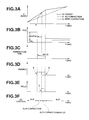
- Figs. 3A ⁇ 3F show a time chart for illustrating operations of the chassis dynamometer system of Fig. 1.
- Fig. 4 is a schematic view showing basic vehicle testing equipment, to facilitate understanding of the present invention.
- Fig. 5 is a block diagram showing a basic control circuit for controlling a running resistance of a dynamometer shown in Fig. 4.
- Fig. 4 shows a basic configuration of a chassis dynamometer 1 used for testing exhaust emissions and other vehicle performance.
- a test vehicle W is mounted and operated on the chassis dynamometer 1, as shown in Fig. 4.
- a dynamometer unit 3 performs a running resistance control, and a driver operates the vehicle attempting to follow a vehicle speed pattern (or driving cycle) shown on a monitor of a driver aid 20.
- the speed pattern is predetermined according to standards or regulations.
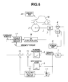
- Fig. 5 shows a basic control circuit for the running resistance control of the dynamometer unit 3.
- a pulse pickup 4 and a frequency-to-voltage converter 7 are configured to detect a vehicle speed Vd of the test vehicle.
- a torque sensor 5 and a strain amplifier 6 detect a torque ⁇ s of the dynamometer unit 3.
- a function generator 8 receives a vehicle speed signal representing the detected actual vehicle speed Vd from the frequency-to-voltage converter 7, and produces an output signal representing a running resistance in accordance with the vehicle speed signal.
- a function generator 9 produces an output signal representing a mechanical loss in response to the vehicle speed signal Vd from the frequency-to-voltage converter 7.
- a differentiating circuit 11 receives the vehicle speed signal Vd from the frequency-to-voltage converter 7 and produces an acceleration signal representing an acceleration by differentiating the detected actual vehicle speed Vd.
- An electric inertia circuit 12 receives the acceleration signal from the differentiating circuit 11 and produces an inertia signal representing an electric inertia by converting the acceleration into the electric inertia.
- Adders 10 and 13 cooperate to determine a load by algebraically adding the running resistance, the mechanical loss and the electric inertia with the positive and negative polarities as shown in Fig. 5, and thereby to produce a command torque signal representing a command torque ⁇ s representing the load.
- a torque control circuit 17 receives the command torque signal ⁇ S from the adder 13 and the actual torque signal ⁇ d from the strain amplifier 6, determines a torque deviation between the command torque ⁇ s and the detected actual torque ⁇ d, produces a control signal in dependence on the torque deviation according to a PI control.
- a dynamometer controller 18 receives the control signal as current command, and controls the dynamometer unit 3 in response to the control signal.
- a vehicle speed pattern for emission testing is generally prepared by using a given vehicle.
- the test vehicle tends to lag behind the target vehicle speed pattern and to become unable to follow up the target vehicle speed pattern (such as a drive cycle of EPAUS6 mode) because of its deficiency in the output.
- Fig. 1 shows a chassis dynamometer system according to one embodiment of the present invention aimed to prevent a test vehicle on a chassis dynamometer from becoming unable to follow up a target.
- the chassis dynamometer system is in the form of a control system including the chassis dynamometer 1 as a controlled system, and a controlling system which, in this example, in the form of a control circuit.
- the chassis dynamometer controlling system of Fig. 1 comprises a monitoring section 14 for monitoring a vehicle speed deviation, and a correcting section 15 for modifying the command torque ⁇ S supplied to the torque control circuit 17 in dependence on a result of a monitoring operation of the monitoring section 14.
- a drive system 40 of this example is in the form of a driver aid as in the basic system of Fig. 5.
- the monitoring section 14 receives a target vehicle speed signal representing the target vehicle speed Vd from the driver aid 40, an actual vehicle speed signal representing the detected actual vehicle speed Vd from the frequency-to-voltage converter 7 and an accelerator opening signal representing an accelerator opening (degree) of the test vehicle W from an accelerator position sensor 42 installed in the test vehicle. By monitoring these input parameters, the monitoring section 14 controls a correcting operation of the correcting section 15 according to a correction control process shown in Fig. 2.
- the correcting section 15 receives the target vehicle speed Vt and the detected actual vehicle speed Vd, and produces a correction signal representing a correction quantity under the control of flags (or condition signals) produced by the monitoring section 14.
- An adder 16 determines a modified command target ⁇ S' by adding the correction quantity determined by the correcting section 15 to the command target ⁇ S outputted from the adder 13.
- control circuit of Fig. 1 is substantially identical to the control circuit of Fig. 5.
- a driver operates the test vehicle, following a target vehicle speed displayed on the driver aid 40.
- the dynamometer unit 3 is controlled to control the running resistance normally in accordance with the command torque ⁇ S outputted from the adder 13.
- the monitoring section 14 compares the detected actual vehicle speed Vd with the target vehicle speed Vt, and determines, at a step 101, whether the vehicle speed deviation ⁇ V of the actual vehicle speed Vd from the target vehicle speed Vt is equal to or greater than a predetermined deviation value. If the speed deviation ⁇ V is equal to or greater than the predetermined deviation value, then the monitoring section 14 further checks whether the accelerator of the test vehicle is in a fully open condition or not, at a step 102. In this example, the answer of the step 102 is affirmative if the accelerator opening A remains equal to 100 % for a time duration equal to or longer than 5 sec. If the vehicle speed deviation ⁇ V is not large or if the accelerator is not in the fully open condition, the monitoring section 14 considers the test vehicle to be in a condition capable of follow up the target vehicle speed Vt, and hence holds the correction section 15 inoperative.
- the monitoring section 14 sets a correction control enable flag at a step 103 as shown at "a" in Fig. 3D.
- the correcting section 15 In response to the correction control enable flag, the correcting section 15 produces the correction signal representing the correction quantity so as to reduce the vehicle speed deviation ⁇ V.
- the adder 16 receives the correction signal, determines a modified command torque ⁇ s' by adding the correction quantity to the command torque ⁇ s determined by the adder 13, and supplies the modified command torque ⁇ s' to the torque control circuit 17.
- the monitoring section 14 checks whether the throttle is in the fully open state at a step 104 following the step 103. When the throttle opening degree decreases from the full throttle condition, the monitoring section 14 sets a hold flag at a step 105 as shown at "c" in Fig. 3E, expecting the driver to control the vehicle speed with the accelerator.
- the correcting section 15 holds the correction quantity constant at a then-existing value as shown in Fig. 3C.
- the monitoring section 14 checks, at a step 106, whether the rate of variation of the target vehicle speed Vt (i.e. the acceleration or deceleration of the target vehicle speed) is gradual. When the rate of variation of the target vehicle speed Vt becomes smaller than a predetermined rate, the monitoring section 14 resets the hold flag at a step 107 as shown at "b" in Fig. 3D, and thereby terminates the correcting operation. Therefore, the chassis dynamometer 1 is restored to the normal control mode for controlling the running resistance without the vehicle speed correcting control on the dynamometer's side.
- Vt rate of variation of the target vehicle speed Vt
- the control system ensures the vehicle's capability of following up the target speed. If, during a driver's operation for following up the target vehicle speed Vt displayed on the driver aid 20, the acceleration of the target vehicle speed Vt increases and the vehicle speed V becomes unable to follow up the target vehicle speed Vt, the control system determines the correction quantity in accordance with the vehicle speed deviation ⁇ V so as to reduce the vehicle speed deviation ⁇ V to zero, adds the correction quantity to the command torque ⁇ s corresponding to the load, and thereby decreases the load so that the vehicle speed can follow up the target speed.
- the control system can maintain the follow-up capability not only when the acceleration increases as in the illustrated example, but also when the deceleration of the target vehicle speed increases. In the case of an increase of the deceleration, the control system maintain the vehicle's capability of following up the target speed by increasing the load.
- the drive system 40 is the drive aid for assisting a human driver in operating the test vehicle W.
- the drive system 40 may be an automatic apparatus for receiving the target vehicle speed Vt and controlling the accelerator of the test vehicle W automatically so as to reduce the vehicle speed deviation.
- the controlling system comprises a correction controller.
- the correction controller of this example comprises the monitoring section 14 and the correcting section 15.
Landscapes
- Physics & Mathematics (AREA)
- General Physics & Mathematics (AREA)
- Testing Of Engines (AREA)
Applications Claiming Priority (2)
| Application Number | Priority Date | Filing Date | Title |
|---|---|---|---|
| JP4303698 | 1998-02-25 | ||
| JP04303698A JP3800792B2 (ja) | 1998-02-25 | 1998-02-25 | シャシーダイナモメータの制御回路 |
Publications (3)
| Publication Number | Publication Date |
|---|---|
| EP0939313A2 true EP0939313A2 (de) | 1999-09-01 |
| EP0939313A3 EP0939313A3 (de) | 1999-12-22 |
| EP0939313B1 EP0939313B1 (de) | 2005-05-11 |
Family
ID=12652700
Family Applications (1)
| Application Number | Title | Priority Date | Filing Date |
|---|---|---|---|
| EP99103579A Expired - Lifetime EP0939313B1 (de) | 1998-02-25 | 1999-02-24 | Steuersystem eines Fahrgestelldynamometers |
Country Status (4)
| Country | Link |
|---|---|
| US (1) | US6157878A (de) |
| EP (1) | EP0939313B1 (de) |
| JP (1) | JP3800792B2 (de) |
| DE (1) | DE69925181T2 (de) |
Cited By (3)
| Publication number | Priority date | Publication date | Assignee | Title |
|---|---|---|---|---|
| US8664007B2 (en) | 2004-10-30 | 2014-03-04 | Roche Diagnostics Operations, Inc. | Immune complex-specific antibodies for increased sensitivity in immunoassay array tests |
| CN103983460A (zh) * | 2014-04-29 | 2014-08-13 | 重庆长安汽车股份有限公司 | 一种车辆内阻测试方法 |
| AT522635A1 (de) * | 2019-06-13 | 2020-12-15 | Avl List Gmbh | Verfahren und Kontrollvorrichtung zum Betreiben eines Prüfstands |
Families Citing this family (9)
| Publication number | Priority date | Publication date | Assignee | Title |
|---|---|---|---|---|
| US6671607B2 (en) * | 2000-05-16 | 2003-12-30 | Nissan Motor Co., Ltd. | Vehicle speed control system |
| JP2003098045A (ja) * | 2001-09-26 | 2003-04-03 | Horiba Ltd | 自動車自動運転システム |
| WO2006055289A2 (en) * | 2004-11-05 | 2006-05-26 | Environmental Systems Products Holdings, Inc. | Universal automotive maintenance component controller apparatus |
| JP4606246B2 (ja) * | 2005-05-16 | 2011-01-05 | 株式会社小野測器 | シャシーダイナモメータ |
| JP4311476B2 (ja) * | 2007-05-11 | 2009-08-12 | トヨタ自動車株式会社 | 回転駆動力源制御装置 |
| JP5252005B2 (ja) * | 2011-03-04 | 2013-07-31 | 株式会社明電舎 | シャシーダイナモメータシステムの暖機運転表示装置 |
| US9020659B2 (en) | 2012-06-15 | 2015-04-28 | Ford Global Technologies, Llc | Dynamometer vehicle operating mode control |
| US11113902B2 (en) * | 2019-04-23 | 2021-09-07 | Innova Electronics Corporation | On board diagnostics drive cycle advisor |
| JP7305492B2 (ja) * | 2019-09-11 | 2023-07-10 | 株式会社Subaru | 車両用モード運転補助システム |
Family Cites Families (7)
| Publication number | Priority date | Publication date | Assignee | Title |
|---|---|---|---|---|
| US4327578A (en) * | 1979-12-19 | 1982-05-04 | Horiba Instruments Incorporated | Dynamometer |
| JPS61110026A (ja) * | 1984-11-02 | 1986-05-28 | Mitsubishi Electric Corp | エンジン試験装置の制御方法 |
| JP2727229B2 (ja) * | 1989-06-07 | 1998-03-11 | 株式会社小野測器 | エンジン試験装置における自動運転時のスロットル予測制御装置 |
| US5447060A (en) * | 1993-11-26 | 1995-09-05 | Schenck Pegasus Corporation | Chasis dynamometer with improved torque measurement |
| US5531107A (en) * | 1995-02-15 | 1996-07-02 | Ganzcorp Investments, Inc. | Method and apparatus for establishing virtual inertia in a chassis dynamometer |
| US5844145A (en) * | 1996-03-01 | 1998-12-01 | Snap-On Technologies, Inc. | Chassis dynamometer employing laterally moving roller assemblies during alignment of vehicle |
| US6009740A (en) * | 1997-02-21 | 2000-01-04 | Horiba Instruments, Inc. | System and method for deadweight calibrating a dynamometer |
-
1998
- 1998-02-25 JP JP04303698A patent/JP3800792B2/ja not_active Expired - Fee Related
-
1999
- 1999-02-19 US US09/253,052 patent/US6157878A/en not_active Expired - Lifetime
- 1999-02-24 EP EP99103579A patent/EP0939313B1/de not_active Expired - Lifetime
- 1999-02-24 DE DE69925181T patent/DE69925181T2/de not_active Expired - Lifetime
Cited By (5)
| Publication number | Priority date | Publication date | Assignee | Title |
|---|---|---|---|---|
| US8664007B2 (en) | 2004-10-30 | 2014-03-04 | Roche Diagnostics Operations, Inc. | Immune complex-specific antibodies for increased sensitivity in immunoassay array tests |
| CN103983460A (zh) * | 2014-04-29 | 2014-08-13 | 重庆长安汽车股份有限公司 | 一种车辆内阻测试方法 |
| CN103983460B (zh) * | 2014-04-29 | 2016-08-31 | 重庆长安汽车股份有限公司 | 一种车辆内阻测试方法 |
| AT522635A1 (de) * | 2019-06-13 | 2020-12-15 | Avl List Gmbh | Verfahren und Kontrollvorrichtung zum Betreiben eines Prüfstands |
| AT522635B1 (de) * | 2019-06-13 | 2022-02-15 | Avl List Gmbh | Verfahren und Kontrollvorrichtung zum Betreiben eines Prüfstands |
Also Published As
| Publication number | Publication date |
|---|---|
| EP0939313B1 (de) | 2005-05-11 |
| DE69925181T2 (de) | 2006-02-23 |
| DE69925181D1 (de) | 2005-06-16 |
| EP0939313A3 (de) | 1999-12-22 |
| JPH11241976A (ja) | 1999-09-07 |
| JP3800792B2 (ja) | 2006-07-26 |
| US6157878A (en) | 2000-12-05 |
Similar Documents
| Publication | Publication Date | Title |
|---|---|---|
| US6157878A (en) | Chassis dynamometer control system | |
| US8151915B2 (en) | Electric drive vehicle | |
| US9818241B2 (en) | Malfunction diagnosing apparatus for vehicle | |
| US5823164A (en) | Throttle control device | |
| CN108357481B (zh) | 防止制动钳损坏的电子驻车控制方法、装置及系统 | |
| JP4595933B2 (ja) | 車両用バッテリ電流検出装置 | |
| US5749063A (en) | Automatic vehicle speed controlling apparatus | |
| EP2318230B1 (de) | Steuergerät für den beschleuniger eines elektrofahrzeugs mit vierradantrieb und verfahren dafür | |
| KR20000053500A (ko) | 자동차 속도 자동 제어 방법 | |
| KR101714212B1 (ko) | 하이브리드 차량의 벨트 연결 전기동력원 제어 방법 및 장치 | |
| JPH10164704A (ja) | 電気自動車のモーター駆動制御装置 | |
| KR100273580B1 (ko) | 스로틀 밸브 위치의 최소값 학습방법 | |
| JPWO2016143762A1 (ja) | 車両の油圧制御装置及び方法 | |
| JPH0599058A (ja) | 車載用制御装置 | |
| JPH0568308A (ja) | 電気自動車の速度制御装置 | |
| JPH07103008A (ja) | 車両用振動低減装置 | |
| JP2819891B2 (ja) | 車両用走行制御装置 | |
| JPH05201228A (ja) | サスペンション制御装置 | |
| JP2006271037A (ja) | 車両速度演算方法及び車両加減速度演算方法 | |
| JP2002323411A (ja) | 車両用エアコンの試験システム | |
| KR100579924B1 (ko) | 전기 자동차의 정속 주행장치 및 그것의 제어방법 | |
| KR100354040B1 (ko) | 차량 자동변속기의 파워 온/오프 판단 제어방법 | |
| KR20040043801A (ko) | 클러스터 모듈의 게이지 제어장치 | |
| JPH03273936A (ja) | 車両用定速走行制御装置 | |
| JPH066069U (ja) | 車速自動制御装置 |
Legal Events
| Date | Code | Title | Description |
|---|---|---|---|
| PUAI | Public reference made under article 153(3) epc to a published international application that has entered the european phase |
Free format text: ORIGINAL CODE: 0009012 |
|
| 17P | Request for examination filed |
Effective date: 19990224 |
|
| AK | Designated contracting states |
Kind code of ref document: A2 Designated state(s): DE GB |
|
| AX | Request for extension of the european patent |
Free format text: AL;LT;LV;MK;RO;SI |
|
| PUAL | Search report despatched |
Free format text: ORIGINAL CODE: 0009013 |
|
| AK | Designated contracting states |
Kind code of ref document: A3 Designated state(s): AT BE CH CY DE DK ES FI FR GB GR IE IT LI LU MC NL PT SE |
|
| AX | Request for extension of the european patent |
Free format text: AL;LT;LV;MK;RO;SI |
|
| AKX | Designation fees paid |
Free format text: DE GB |
|
| 17Q | First examination report despatched |
Effective date: 20040324 |
|
| GRAP | Despatch of communication of intention to grant a patent |
Free format text: ORIGINAL CODE: EPIDOSNIGR1 |
|
| GRAS | Grant fee paid |
Free format text: ORIGINAL CODE: EPIDOSNIGR3 |
|
| GRAA | (expected) grant |
Free format text: ORIGINAL CODE: 0009210 |
|
| AK | Designated contracting states |
Kind code of ref document: B1 Designated state(s): DE GB |
|
| REG | Reference to a national code |
Ref country code: GB Ref legal event code: FG4D |
|
| REF | Corresponds to: |
Ref document number: 69925181 Country of ref document: DE Date of ref document: 20050616 Kind code of ref document: P |
|
| PLBE | No opposition filed within time limit |
Free format text: ORIGINAL CODE: 0009261 |
|
| STAA | Information on the status of an ep patent application or granted ep patent |
Free format text: STATUS: NO OPPOSITION FILED WITHIN TIME LIMIT |
|
| 26N | No opposition filed |
Effective date: 20060214 |
|
| PGFP | Annual fee paid to national office [announced via postgrant information from national office to epo] |
Ref country code: DE Payment date: 20170217 Year of fee payment: 19 |
|
| PGFP | Annual fee paid to national office [announced via postgrant information from national office to epo] |
Ref country code: GB Payment date: 20170216 Year of fee payment: 19 |
|
| REG | Reference to a national code |
Ref country code: DE Ref legal event code: R119 Ref document number: 69925181 Country of ref document: DE |
|
| GBPC | Gb: european patent ceased through non-payment of renewal fee |
Effective date: 20180224 |
|
| PG25 | Lapsed in a contracting state [announced via postgrant information from national office to epo] |
Ref country code: DE Free format text: LAPSE BECAUSE OF NON-PAYMENT OF DUE FEES Effective date: 20180901 |
|
| PG25 | Lapsed in a contracting state [announced via postgrant information from national office to epo] |
Ref country code: GB Free format text: LAPSE BECAUSE OF NON-PAYMENT OF DUE FEES Effective date: 20180224 |