EP0938105B1 - Powder for permanent magnet, method for its production and anisotropic permanent magnet made using said powder - Google Patents
Powder for permanent magnet, method for its production and anisotropic permanent magnet made using said powder Download PDFInfo
- Publication number
- EP0938105B1 EP0938105B1 EP97909739A EP97909739A EP0938105B1 EP 0938105 B1 EP0938105 B1 EP 0938105B1 EP 97909739 A EP97909739 A EP 97909739A EP 97909739 A EP97909739 A EP 97909739A EP 0938105 B1 EP0938105 B1 EP 0938105B1
- Authority
- EP
- European Patent Office
- Prior art keywords
- fine particles
- needle
- powder
- permanent magnet
- coating
- Prior art date
- Legal status (The legal status is an assumption and is not a legal conclusion. Google has not performed a legal analysis and makes no representation as to the accuracy of the status listed.)
- Expired - Lifetime
Links
Images
Classifications
-
- H—ELECTRICITY
- H01—ELECTRIC ELEMENTS
- H01F—MAGNETS; INDUCTANCES; TRANSFORMERS; SELECTION OF MATERIALS FOR THEIR MAGNETIC PROPERTIES
- H01F1/00—Magnets or magnetic bodies characterised by the magnetic materials therefor; Selection of materials for their magnetic properties
- H01F1/01—Magnets or magnetic bodies characterised by the magnetic materials therefor; Selection of materials for their magnetic properties of inorganic materials
- H01F1/03—Magnets or magnetic bodies characterised by the magnetic materials therefor; Selection of materials for their magnetic properties of inorganic materials characterised by their coercivity
- H01F1/032—Magnets or magnetic bodies characterised by the magnetic materials therefor; Selection of materials for their magnetic properties of inorganic materials characterised by their coercivity of hard-magnetic materials
- H01F1/04—Magnets or magnetic bodies characterised by the magnetic materials therefor; Selection of materials for their magnetic properties of inorganic materials characterised by their coercivity of hard-magnetic materials metals or alloys
- H01F1/047—Alloys characterised by their composition
- H01F1/053—Alloys characterised by their composition containing rare earth metals
- H01F1/055—Alloys characterised by their composition containing rare earth metals and magnetic transition metals, e.g. SmCo5
- H01F1/059—Alloys characterised by their composition containing rare earth metals and magnetic transition metals, e.g. SmCo5 and Va elements, e.g. Sm2Fe17N2
-
- H—ELECTRICITY
- H01—ELECTRIC ELEMENTS
- H01F—MAGNETS; INDUCTANCES; TRANSFORMERS; SELECTION OF MATERIALS FOR THEIR MAGNETIC PROPERTIES
- H01F1/00—Magnets or magnetic bodies characterised by the magnetic materials therefor; Selection of materials for their magnetic properties
- H01F1/01—Magnets or magnetic bodies characterised by the magnetic materials therefor; Selection of materials for their magnetic properties of inorganic materials
- H01F1/03—Magnets or magnetic bodies characterised by the magnetic materials therefor; Selection of materials for their magnetic properties of inorganic materials characterised by their coercivity
- H01F1/0302—Magnets or magnetic bodies characterised by the magnetic materials therefor; Selection of materials for their magnetic properties of inorganic materials characterised by their coercivity characterised by unspecified or heterogeneous hardness or specially adapted for magnetic hardness transitions
- H01F1/0306—Metals or alloys, e.g. LAVES phase alloys of the MgCu2-type
Definitions
- the present invention relates to a bonded permanent magnet material for use in a motor, a speaker, an actuator or the like and is directed especially to an exchange spring magnet having a composite structure of a hard magnetic phase represented by Sm 2 Be 17 N x and a soft magnetic phase of Fe or Fe-Co alloy in the same texture. It also relates to a powder for a permanent magnet with well-balanced high magnetization and high coercive force, and to a method for producing the powder and an anisotropic permanent magnet made from the powder.
- An exchange spring magnet behaves as a single hard magnetic material because of the strong exchange bonding force between the two phases described above and, at the same time, it exhibits such specific behavior that magnetization reversibly springs back upon a change of external magnetic field in the second quadrant of the demagnetization curve. Recently, the use of this effect has attracted special interest.
- the first method causes the soft magnetic phase separation as a result of precipitation from a molten alloy with a controlled composition on solidification during cooling or subsequent heat treatment after cooling, and includes various methods, for example, the method described in Unexamined Patent Publicatio No. Hei 5-135928 wherein a Nd-Fe-B alloy containing excess Fe is melted solidified and heat- treated to obtain a micro-crystal aggregate of a Fe 3 B phase (soft magnetic phase) and a Nd 2 Fe 14 B phase (hard magnetic layer), and the method described in Unexamined Patent Publication No.
- the second method uses needle- like iron powder as a base material and changes the surface portion into a hard magnetic phase by using a chemical treatment and a heat treatment.
- Unexamined Patent Publication No. Hei 7-272913 describes a raw material for a permanent magnet, comprising needle-like iron powder, an aluminum phosphate coating layer, a rare earth diffusion layer or a rare earth-iron-boron diffusion layer or a rare earth- boron- nitrogen diffusion layer, and an aluminum phosphate coating layer, in sequence on the surface of the needle-like iron powder, and also describes a method for producing the raw material, which comprises the steps of heating FeOOH (Goethite) needle- like grains coated with aluminum phosphate in a hydrogen atmosphere to 300-500°C, thereby reducing FeOOH to Fe (needle-like iron powder); heating to 650-1000°C in an argon atmosphere in the presence of rare earth or rare earth and boron, thereby diffusing rare earth, or rare earth and boron into the surface of the aluminum phosphat
- magnetic characteristics are improved by the oxidizing inhibition effect due to the double coating of aluminum phosphate and the action as a magnetic domain wall thereof, but stable excellent magnetic characteristics can not be obtained.
- the reason for this is that during the evaporation and diffusion of Sm, aluminum phosphate is decomposed and reduced by a strong reducing force of Sm and Al is incorporated into the iron powder, whereas Sm is oxidized and the hard magnetic phase of the Sm-Fe-N alloy is not easily formed, resulting in deterioration of magnetic characteristics.
- the present invention is directed to an improvement in the manufacture of exchange spring magnets using a modification of the second method and seeks to provide a powder for permanent magnets having stable magnetic characteristics, by homogeneously diffusing and forming a hard magnetic layer on the surface of needle- like Fe fine particles a method for producing such a powder, and an anisotropic permanent magnet made from the powder.
- the powder for a permanent magnet according to the present invention comprises needle-like fine particles of Fe or Fe-Co alloy as a base material, a hard magnetic layer containing Fe, Sm and N on the surface of the needle-like fine particles, and a separation layer of an oxide of rare earth element (R) provided outside the hard magnetic layer.
- R rare earth element
- the powder for a permanent magnet of the present invention preferably comprises a sintered body powder having a particle diameter of 10 to 100 ⁇ m.
- a sintered body powder having a particle diameter of 10 to 100 ⁇ m.
- the separation layer is coated with one or more of Zn, Sn and Pb, whereby an intermetallic compound is formed between Sm and these low- melting point metals, thereby markedly improving coercive force.
- rare earth elements one or more of Nd, La, Ce, Pr, Sm and Y can be used.
- the invention provides also a method which comprises coating the surface of needle-like fine particles of Fe or Fe-Co alloy having a major axis of 0.1 to 3 ⁇ m and a minor axis of 0.03 to 0.4 ⁇ m, with a hydroxide of rare earth element (R) using wet deposition method; subjecting the fine particles to filtration and drying; heat-treating the dried fine particles in an atmosphere of hydrogen gas or an inert gas, or a mixture thereof; coating the resultant needle- like fine particles of Fe or Fe-Co alloy coated with an oxide of rare earth element (R) with Sm in a vacuum at a temperature of 500 to 1000°C; further heat- treating the fine particles to form a compound layer containing Fe and Sm on the surface of the needle- like fine particles; and subjecting the heat- treated fine particles to a nitriding treatment in a nitrogen-containing gas.
- a hydroxide of rare earth element (R) using wet deposition method
- the invention provides a method which comprises coating the surface of needle-like fine particles of ⁇ -FeOOH or Co-doped ⁇ -FeOOH having having a major axis of 0.1 to 3 ⁇ m and a minor axis of 0.03 to 0.4 ⁇ m, with a hydroxide of rare earth element (R) using a wet deposition method; subjecting the fine particles to filtration and drying; heat-treating the dried fine particles in an atmosphere of a hydrogen-containing gas; coating the resultant oxide of R-coated fine particles of Fe or Fe-Co alloy with Sm in a vacuum at a temperature of 500 to 1000°C; further heat- treating the fine particles to form a compound layer containing Fe and Sm on the surface of the needle-like fine particles; and subjecting the heat-treated fine particles to a nitriding treatment in a nitrogen-containing gas.
- R rare earth element
- both of the methods described above include between the further heat treatment and the nitriding treatment the further step of compressing the fine particles in a magnetic field; sintering the compressed body at a temperature of 700 to 1000°C ; and grinding the sintered one into particles having a particle diameter of 10 to 100 ⁇ m.
- the invention provides an anisotropic permanent magnet obtained by kneading a powder as described above with a resin, and hot- pressing the mixture in a magnetic field.
- the invention provides an anisotropic permanent magnet which is obtained by hot-pressing a powder. as described above whereby the Zn, Sn or Pb binds the powder particles.
- the major axis and the minor axis of the needle- like fine particles of Fe or Fe-Co alloy are adjusted to 0.1-3 ⁇ m and 0. 03-0.4 ⁇ m, respectively, and the aspect ratio is preferably adjusted to not less than 2 so as to exert shape anisotropy.
- the aspect ratio exceeds 15, twin is produced and the fluidity of the fine particles is poor, resulting in difficult handling.
- the minor axis is smaller than 0.03 ⁇ m, it is difficult to control the thickness of the Sm diffusion layer in the formation of the following Fe-Sm compound layer and, therefore, stable magnetic characteristics cannot be obtained.
- the method for producing the needle- like Fe fine particles includes, for example, reducing FeOOH as a raw material, and electro-deposition method.
- the element constituting the separation layer a rare earth element or CaO is preferable.
- the rare earth element Pr or Nd can be preferably used in view of the adhesion they promotes.
- the purpose of forming the separation layer lies in separating the needle-like fine particles as described above, resulting in inhibition of reduction of the aspect ratio.
- the element constituting the separation layer has larger affinity for oxygen than that of the element constituting the hard magnetic layer.
- the separation layer has high adhesion.
- the method for forming the separation layer includes, for example, adding a salt of rare earth element to a suspension of FeOOH needle-like fine particles, needle-like Fe fine particles or Fe-Co alloy needle-like fine particles, adding NH 4 OH or the like to alkalify the solution, and depositing a hydroxide of rare earth element on the surface of the above needle-like fine particles, thereby coating the surface with the separation layer of an oxide of rare earth element.
- the known methods such as normal addition, reverse addition, simultaneous addition, gas precipitation, water-heat treatment and coprecipitation can be used.
- the thickness of the Fe-Sm compound to be formed on the surface of the needle-like Fe fine particles or Fe-Co needle-like fine particles is suitably from 0.01 to 0.1 ⁇ m, preferably from 0.02 to 0.08 ⁇ m, and more preferably from 0. 02 to 0.05 ⁇ m, in terms of the total thickness of both sides.
- the thickness of the iron fine particles exceeds 0.2 ⁇ m in the direction of short axis, the magnetic domain wall is present in a stable state and the coercive force is drastically lowered.
- the nitriding treatment involves formation of a hard magnetic layer represented by Sm 2 Fe 17 N x (X is about 3) by the introduction of N into the Fe-Sm compound layer, and is conducted by a heat treatment at a temperature of 400 ⁇ 600 °C in nitrogen, ammonia or a nitrogen-containing gas prepared by adding hydrogen to the gas.
- the powder for the permanent magnet comprising the sintered body powder is obtained by the method described above and when the sintering temperature is lower than 700°C, the density is not increased. On the other hand, when the sintering temperature exceeds 1000°C, coarsening of the particles occurs, resulting in deterioration of magnetic characteristics.
- a sintered body powder is obtained by grinding sintered needle-like fine particles, it is preferable that the sintered needle- like fine particles are ground into pieces having a particle diameter of 10 to 100 ⁇ m. When the particle diameter is smaller than 10 ⁇ m, high orientation is not easily obtained. On the other hand, when the particle diameter is larger than 100 ⁇ m, the pressurized powder density is lowered.
- ⁇ -FeOOH needle- like fine particles as a starting material.
- 75 g of the ⁇ -FeOOH needle-like fine particles were fed into 1500 mililiter of pure water and the mixture was sufficiently stirred to obtain a suspension.
- a predetermined amount of a nitrate aqueous solution (concentration: 0.25 mol/liter) of a raw material for misch metal (Mm) (oxide mixture of La, Ce, Pr and Nd) or a Nd(NO 3 ) 3 aqueous solution (concentration: 0.25 mol/liter) was fed into the suspension and the mixture was further stirred for 1 hour until homogeneously mixed.
- Mm misch metal
- Nd(NO 3 ) 3 aqueous solution concentration: 0.25 mol/liter
- the ⁇ -FeOOH needle- like fine particles coated with R(OH) 3 obtained as described above were filtered and dried, and the resultant dried cake was ground to obtain a raw material for reducing treatment.
- the raw material was fed into a vacuum rotary heat- treating reactor and subjected to a reducing treatment at a temperature of 500°C for 1 hour with passing hydrogen gas through the reactor at a rate of 3 liters per minute to obtain needle-like Fe fine particles coated with fine particles of R 2 0 3 .
- the fine particle raw material may also be heat-treated in an atmosphere before subjecting to the reducing treatment in order to coat with R 2 O 3 more uniformly.
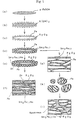
- a schematic diagram of the needle-like Fe fine particles coated with fine particles of R 2 O 3 is shown in Fig. 1(c).
- a hydrogen-containing gas must be used as the atmosphere on heat treatment in order to obtain needle- like Fe fine particles coated with an oxide of a rare earth element.
- a hydrogen-containing gas is not necessarily required, and an inert gas such as nitrogen, Ar or the like can also be used.
- nitriding treatment was conducted at a temperature of 500°C for 3 hours while passing ammonia gas through the reactor under an atmosphere while rotating the vacuum rotary heat- treating reactor.
- a Sm 2 Fe 17 N x layer was formed on the surface of the needle- like Fe fine particles.
- 10% by weight of Zn powder was fed into the reactor while passing an Ar gas through the reactor and, after the pressure of the reactor was decreased to 10 -3 .
- Torr heat treatment was conducted at a temperature of 400°C for 1 hour while rotating the reactor. As a result, the reactor was filled with vapor of Zn. Subsequently, fine particles of R 2 O 3 constituting the separation layer were coated with Zn by slowly cooling.
- FIG. 1(e) A schematic diagram of the needle- like Fe fine particles is shown in Fig. 1(e).
- a zinc coating treatment for example, coating by photo- decomposition of zinc (zinc coating method by adding needle- like Fe particles to a diethylzinc/normal hexane solution and exposing to ultraviolet radiation, thereby decomposing diethylzinc to form metallic zinc) can be used, in addition to the above method.
- a low-melting point metal other than zinc e. g. tin, lead
- tin, lead can also be used in combination.
- the nitrided Zn-coated needle-like Fe fine particles made by the above steps A (1) to A(5) were pressed under a pressure of 2 t/cm 2 with orienting in a magnetic field of 15 kOe to form a pellet- like body. Then, this pellet-like body was hot-pressed in an Ar gas atmosphere at a temperature of 420°C under a pressure of 7 t/cm 2 for 2 hours by using a hot press to obtain an article as shown in Fig. 1(f).
- the above pellet-like body was hot-rolled at a temperature of 300°C using a rolling mill so that the thickness was 2 cm, and the resultant body was cut and ground to obtain an article as shown in Fig. 1(f).
- the above pellet-like body was hot- extruded at a temperature of 300°C using an extruder, and the resultant body was cut to obtain an article as shown in Fig. 1(f).
- the nitrided zinc- coated needle-like Fe fine particles made by the above steps A(1) to A(5) were mixed and kneaded with an epoxy resin (an amount of about 3% by weight to the fine particles raw material) and the mixture was pressed under a pressure of 2 t/cm 2 while orienting in a magnetic field of 15 kOe, and then cured at a temperature of 120°C for 1 hour to obtain a resin bonded permanent magnet.
- the needle-like Fe fine particles, wherein a layer of Sm 2 Fe 17 is formed on the surface, made by the above steps A(1) to A(4) were pressed under a pressure of 2 t/cm 2 while orienting in a magnetic field of 15 kOe, and then the pressed body was fed into an electric furnace and sintered in an Ar gas atmosphere at a temperature of 950°C for 1 hour to obtain a sintered body as shown in Fig. 1 (g).
- This sintered body was ground into particles having a size of 50 to 100 a m and then nitrided at a temperature of 500°C for 3 hours while passing a nitrogen gas (ammonia gas or a mixed gas of hydrogen and ammonia can also be used) through the furnace.
- a nitrogen gas ammonia gas or a mixed gas of hydrogen and ammonia can also be used
- a Sm 2 Fe 17 N x layer was formed on the surface of the needle- like Fe fine particles (Fig. 1(h)).
- the nitrided needle- like Fe fine particles sintered body powder was mixed and kneaded with an epoxy resin (an amount of about 2% by weight to the sintered body powder) and the mixture was pressed under a pressure of 2 t/cm 2 while orienting in a magnetic field of 15 kOe, and then cured at a temperature of 120°C for 1 hour to obtain a resin bonded permanent magnet as shown in Fig. 1(i).
- the above fine needle-like ⁇ - FeOOH fine particles manufactured by Titanium Industries Co., Ltd. as the starting raw material were directly reduced in hydrogen at a temperature of 500°C without forming a separation layer and, after reducing, Sm-Fe compound layer was formed under the same conditions as described above. Then, the resultant compound was subjected to a nitriding treatment and Zn-coating treatment in the same manner as in Example 4 to make a resin bonded magnet.
- a 10% aluminum phosphate- ethanol solution was added to the above fine needle-like ⁇ -FeOOH fine particles manufactured by Titanium Industries Co., Ltd. as the starting raw material and ethanol was evaporated by heating, thereby to coat the fine particles with aluminum phosphate in an amount of 5 mol % relative to ⁇ -FeOOH.
- Sm-Fe compound layer was formed under the same conditions as described above and then a resin bonded magnet was made in the same manner as in Example 5.
- the magnets were made in the manner as described above from six starting materials as shown in Table 1 below.
- the results of elemental analysis after formation of Sm-Fe compound layer are shown by atomic ratio in Table 1. All of the resultant magnets were cut into pieces having a section of 10 mm x 10 mm, and then performances of the respective magnets were determined by using a direct current BH tracer (manufactured by Toshiba Industries Co., Ltd.). The results are shown in Table 2 below.
- the magnet of Comparative Example 1 hardly exhibits magnetic performance because intragranular bonding and grain growth occurred on reducing treatment and heat treatment for forming the Sm-Fe compound layer and the aspect ratio was reduced to 1-3.
Landscapes
- Engineering & Computer Science (AREA)
- Power Engineering (AREA)
- Chemical & Material Sciences (AREA)
- Crystallography & Structural Chemistry (AREA)
- Inorganic Chemistry (AREA)
- Hard Magnetic Materials (AREA)
- Powder Metallurgy (AREA)
- Manufacturing Cores, Coils, And Magnets (AREA)
Applications Claiming Priority (3)
| Application Number | Priority Date | Filing Date | Title |
|---|---|---|---|
| JP29404996 | 1996-11-06 | ||
| JP29404996A JP3647995B2 (ja) | 1996-11-06 | 1996-11-06 | 永久磁石用粉末並びにその製造方法および該粉末を用いた異方性永久磁石 |
| PCT/JP1997/004012 WO1998020507A1 (fr) | 1996-11-06 | 1997-11-04 | Poudre pour aimant permanent, procede de production associe et aimant permanent anisotrope fabrique avec ladite poudre |
Publications (3)
| Publication Number | Publication Date |
|---|---|
| EP0938105A1 EP0938105A1 (en) | 1999-08-25 |
| EP0938105A4 EP0938105A4 (enExample) | 1999-09-15 |
| EP0938105B1 true EP0938105B1 (en) | 2003-10-22 |
Family
ID=17802626
Family Applications (1)
| Application Number | Title | Priority Date | Filing Date |
|---|---|---|---|
| EP97909739A Expired - Lifetime EP0938105B1 (en) | 1996-11-06 | 1997-11-04 | Powder for permanent magnet, method for its production and anisotropic permanent magnet made using said powder |
Country Status (6)
| Country | Link |
|---|---|
| US (1) | US6328817B1 (enExample) |
| EP (1) | EP0938105B1 (enExample) |
| JP (1) | JP3647995B2 (enExample) |
| AT (1) | ATE252764T1 (enExample) |
| DE (1) | DE69725750T2 (enExample) |
| WO (1) | WO1998020507A1 (enExample) |
Families Citing this family (12)
| Publication number | Priority date | Publication date | Assignee | Title |
|---|---|---|---|---|
| US6710693B2 (en) * | 2001-03-23 | 2004-03-23 | Nec Tokin Corporation | Inductor component containing permanent magnet for magnetic bias and method of manufacturing the same |
| JP2002359126A (ja) * | 2001-05-30 | 2002-12-13 | Nec Tokin Corp | インダクタンス部品 |
| DE10155898A1 (de) * | 2001-11-14 | 2003-05-28 | Vacuumschmelze Gmbh & Co Kg | Induktives Bauelement und Verfahren zu seiner Herstellung |
| WO2006004998A2 (en) * | 2004-06-30 | 2006-01-12 | University Of Dayton | Anisotropic nanocomposite rare earth permanent magnets and method of making |
| JP4834869B2 (ja) * | 2007-04-06 | 2011-12-14 | Necトーキン株式会社 | 永久磁石材料とそれを用いた永久磁石およびその製造方法 |
| US8339227B2 (en) * | 2007-12-12 | 2012-12-25 | Panasonic Corporation | Inductance part and method for manufacturing the same |
| DE102012204083A1 (de) * | 2012-03-15 | 2013-09-19 | Siemens Aktiengesellschaft | Nanopartikel, Permanentmagnet, Motor und Generator |
| US9607760B2 (en) | 2012-12-07 | 2017-03-28 | Samsung Electronics Co., Ltd. | Apparatus for rapidly solidifying liquid in magnetic field and anisotropic rare earth permanent magnet |
| JP7636005B2 (ja) * | 2020-07-28 | 2025-02-26 | 国立研究開発法人産業技術総合研究所 | 異方性磁石微粒子およびその製造方法 |
| CN115472373A (zh) | 2021-06-10 | 2022-12-13 | 日亚化学工业株式会社 | SmFeN系各向异性磁性粉末的制造方法和SmFeN系各向异性磁性粉末 |
| CN115472409A (zh) | 2021-06-10 | 2022-12-13 | 日亚化学工业株式会社 | SmFeN系稀土磁体的制造方法 |
| CN115881415A (zh) | 2021-09-27 | 2023-03-31 | 日亚化学工业株式会社 | SmFeN系稀土类磁体的制造方法 |
Family Cites Families (7)
| Publication number | Priority date | Publication date | Assignee | Title |
|---|---|---|---|---|
| US4165232A (en) * | 1978-09-15 | 1979-08-21 | Basf Aktiengesellschaft | Manufacture of ferromagnetic metal particles essentially consisting of iron |
| US5466308A (en) * | 1982-08-21 | 1995-11-14 | Sumitomo Special Metals Co. Ltd. | Magnetic precursor materials for making permanent magnets |
| US5183515A (en) * | 1989-11-07 | 1993-02-02 | Unitika Ltd. | Fibrous anisotropic permanent magnet and production process thereof |
| JP3109637B2 (ja) * | 1993-12-10 | 2000-11-20 | 日亜化学工業株式会社 | 異方性針状磁性粉末およびそれを用いたボンド磁石 |
| JPH07272913A (ja) * | 1994-03-30 | 1995-10-20 | Kawasaki Teitoku Kk | 永久磁石原料、その製造法及び永久磁石 |
| JPH08203715A (ja) * | 1995-01-30 | 1996-08-09 | Takahashi Yoshiaki | 永久磁石原料及びその製造法 |
| US5840375A (en) * | 1995-06-22 | 1998-11-24 | Shin-Etsu Chemical Co., Ltd. | Method for the preparation of a highly corrosion resistant rare earth based permanent magnet |
-
1996
- 1996-11-06 JP JP29404996A patent/JP3647995B2/ja not_active Expired - Fee Related
-
1997
- 1997-11-04 DE DE69725750T patent/DE69725750T2/de not_active Expired - Lifetime
- 1997-11-04 EP EP97909739A patent/EP0938105B1/en not_active Expired - Lifetime
- 1997-11-04 AT AT97909739T patent/ATE252764T1/de not_active IP Right Cessation
- 1997-11-04 US US09/284,446 patent/US6328817B1/en not_active Expired - Fee Related
- 1997-11-04 WO PCT/JP1997/004012 patent/WO1998020507A1/ja not_active Ceased
Also Published As
| Publication number | Publication date |
|---|---|
| DE69725750T2 (de) | 2004-08-19 |
| ATE252764T1 (de) | 2003-11-15 |
| JPH10144509A (ja) | 1998-05-29 |
| EP0938105A1 (en) | 1999-08-25 |
| DE69725750D1 (de) | 2003-11-27 |
| US6328817B1 (en) | 2001-12-11 |
| WO1998020507A1 (fr) | 1998-05-14 |
| EP0938105A4 (enExample) | 1999-09-15 |
| JP3647995B2 (ja) | 2005-05-18 |
Similar Documents
| Publication | Publication Date | Title |
|---|---|---|
| US5454998A (en) | Method for producing permanent magnet | |
| US5282904A (en) | Permanent magnet having improved corrosion resistance and method for producing the same | |
| US5716462A (en) | Magnetic material and bonded magnet | |
| US7618497B2 (en) | R-T-B based rare earth permanent magnet and method for production thereof | |
| EP0938105B1 (en) | Powder for permanent magnet, method for its production and anisotropic permanent magnet made using said powder | |
| EP0553527B1 (en) | Powder material for rare earth-iron-boron based permanent magnets | |
| CA2571401A1 (en) | Anisotropic nanocomposite rare earth permanent magnets and method of making | |
| EP0311049B1 (en) | Corrosion resistant rare earth metal magnet | |
| EP0249973B1 (en) | Permanent magnetic material and method for producing the same | |
| CN108417334A (zh) | R-t-b系烧结磁铁 | |
| WO1988006797A1 (fr) | Aimant a base de fer-elements de terres rares et procede de production | |
| EP0255939B1 (en) | Rare earth magnet and rare earth magnet alloy powder having high corrosion resistance | |
| JPH08162312A (ja) | 永久磁石材料、永久磁石及び永久磁石の製造方法 | |
| JP2705985B2 (ja) | 磁性材料、それから成る磁石及びそれらの製造方法 | |
| EP3633696B1 (en) | Rare earth sintered magnet | |
| EP0323125B1 (en) | Rare earth permanent magnet | |
| JPH1053844A (ja) | 希土類−鉄−ボロン系磁石合金及びその製造法並びに該希土類−鉄−ボロン系磁石合金を用いたボンド磁石 | |
| US5447578A (en) | Corrosion-resistant rare earth metal-transition metal series magnets and method of producing the same | |
| US5167914A (en) | Rare earth magnet having excellent corrosion resistance | |
| DE2121596A1 (de) | Hartmagnetische legierung | |
| JPH0422010B2 (enExample) | ||
| JPH0881741A (ja) | 磁石材料およびそれを用いた永久磁石 | |
| JPH05234729A (ja) | 希土類−鉄−窒素系磁石粉末及びその製造方法 | |
| JP3488354B2 (ja) | 微細結晶永久磁石合金及び等方性永久磁石粉末の製造方法 | |
| JPH11340020A (ja) | 磁石材料とその製造方法、およびそれを用いたボンド磁石 |
Legal Events
| Date | Code | Title | Description |
|---|---|---|---|
| PUAI | Public reference made under article 153(3) epc to a published international application that has entered the european phase |
Free format text: ORIGINAL CODE: 0009012 |
|
| 17P | Request for examination filed |
Effective date: 19990602 |
|
| AK | Designated contracting states |
Kind code of ref document: A1 Designated state(s): AT DE FR GB NL SE |
|
| A4 | Supplementary search report drawn up and despatched |
Effective date: 19990730 |
|
| AK | Designated contracting states |
Kind code of ref document: A4 Designated state(s): AT DE FR GB NL SE |
|
| RIC1 | Information provided on ipc code assigned before grant |
Free format text: 6H 01F 1/06 A, 6H 01F 1/08 B, 6H 01F 1/059 B |
|
| 17Q | First examination report despatched |
Effective date: 20010427 |
|
| GRAH | Despatch of communication of intention to grant a patent |
Free format text: ORIGINAL CODE: EPIDOS IGRA |
|
| GRAS | Grant fee paid |
Free format text: ORIGINAL CODE: EPIDOSNIGR3 |
|
| GRAA | (expected) grant |
Free format text: ORIGINAL CODE: 0009210 |
|
| RAP1 | Party data changed (applicant data changed or rights of an application transferred) |
Owner name: SANTOKU CORPORATION |
|
| AK | Designated contracting states |
Kind code of ref document: B1 Designated state(s): AT DE FR GB NL SE |
|
| REG | Reference to a national code |
Ref country code: GB Ref legal event code: FG4D |
|
| REF | Corresponds to: |
Ref document number: 69725750 Country of ref document: DE Date of ref document: 20031127 Kind code of ref document: P |
|
| REG | Reference to a national code |
Ref country code: SE Ref legal event code: TRGR |
|
| ET | Fr: translation filed | ||
| PLBE | No opposition filed within time limit |
Free format text: ORIGINAL CODE: 0009261 |
|
| STAA | Information on the status of an ep patent application or granted ep patent |
Free format text: STATUS: NO OPPOSITION FILED WITHIN TIME LIMIT |
|
| 26N | No opposition filed |
Effective date: 20040723 |
|
| PGFP | Annual fee paid to national office [announced via postgrant information from national office to epo] |
Ref country code: GB Payment date: 20051024 Year of fee payment: 9 |
|
| PGFP | Annual fee paid to national office [announced via postgrant information from national office to epo] |
Ref country code: FR Payment date: 20051110 Year of fee payment: 9 |
|
| PGFP | Annual fee paid to national office [announced via postgrant information from national office to epo] |
Ref country code: SE Payment date: 20051114 Year of fee payment: 9 Ref country code: NL Payment date: 20051114 Year of fee payment: 9 |
|
| PGFP | Annual fee paid to national office [announced via postgrant information from national office to epo] |
Ref country code: AT Payment date: 20051115 Year of fee payment: 9 |
|
| PG25 | Lapsed in a contracting state [announced via postgrant information from national office to epo] |
Ref country code: AT Free format text: LAPSE BECAUSE OF NON-PAYMENT OF DUE FEES Effective date: 20061104 |
|
| PG25 | Lapsed in a contracting state [announced via postgrant information from national office to epo] |
Ref country code: SE Free format text: LAPSE BECAUSE OF NON-PAYMENT OF DUE FEES Effective date: 20061105 |
|
| PG25 | Lapsed in a contracting state [announced via postgrant information from national office to epo] |
Ref country code: NL Free format text: LAPSE BECAUSE OF NON-PAYMENT OF DUE FEES Effective date: 20070601 |
|
| EUG | Se: european patent has lapsed | ||
| GBPC | Gb: european patent ceased through non-payment of renewal fee |
Effective date: 20061104 |
|
| NLV4 | Nl: lapsed or anulled due to non-payment of the annual fee |
Effective date: 20070601 |
|
| REG | Reference to a national code |
Ref country code: FR Ref legal event code: ST Effective date: 20070731 |
|
| PG25 | Lapsed in a contracting state [announced via postgrant information from national office to epo] |
Ref country code: GB Free format text: LAPSE BECAUSE OF NON-PAYMENT OF DUE FEES Effective date: 20061104 |
|
| PG25 | Lapsed in a contracting state [announced via postgrant information from national office to epo] |
Ref country code: FR Free format text: LAPSE BECAUSE OF NON-PAYMENT OF DUE FEES Effective date: 20061130 |
|
| PGFP | Annual fee paid to national office [announced via postgrant information from national office to epo] |
Ref country code: DE Payment date: 20101119 Year of fee payment: 14 |
|
| REG | Reference to a national code |
Ref country code: DE Ref legal event code: R119 Ref document number: 69725750 Country of ref document: DE Effective date: 20130601 |
|
| PG25 | Lapsed in a contracting state [announced via postgrant information from national office to epo] |
Ref country code: DE Free format text: LAPSE BECAUSE OF NON-PAYMENT OF DUE FEES Effective date: 20130601 |