EP0938105B1 - Powder for permanent magnet, method for its production and anisotropic permanent magnet made using said powder - Google Patents
Powder for permanent magnet, method for its production and anisotropic permanent magnet made using said powder Download PDFInfo
- Publication number
- EP0938105B1 EP0938105B1 EP97909739A EP97909739A EP0938105B1 EP 0938105 B1 EP0938105 B1 EP 0938105B1 EP 97909739 A EP97909739 A EP 97909739A EP 97909739 A EP97909739 A EP 97909739A EP 0938105 B1 EP0938105 B1 EP 0938105B1
- Authority
- EP
- European Patent Office
- Prior art keywords
- fine particles
- needle
- powder
- permanent magnet
- coating
- Prior art date
- Legal status (The legal status is an assumption and is not a legal conclusion. Google has not performed a legal analysis and makes no representation as to the accuracy of the status listed.)
- Expired - Lifetime
Links
- 239000000843 powder Substances 0.000 title claims abstract description 35
- 238000000034 method Methods 0.000 title claims description 22
- 238000004519 manufacturing process Methods 0.000 title claims description 11
- 239000010419 fine particle Substances 0.000 claims abstract description 93
- 229910052742 iron Inorganic materials 0.000 claims abstract description 22
- 238000000926 separation method Methods 0.000 claims abstract description 21
- 229910045601 alloy Inorganic materials 0.000 claims abstract description 20
- 239000000956 alloy Substances 0.000 claims abstract description 20
- 229910017061 Fe Co Inorganic materials 0.000 claims abstract description 16
- 239000000463 material Substances 0.000 claims abstract description 7
- 229910052757 nitrogen Inorganic materials 0.000 claims abstract description 6
- 238000000576 coating method Methods 0.000 claims description 24
- 239000011248 coating agent Substances 0.000 claims description 23
- 238000010438 heat treatment Methods 0.000 claims description 19
- 239000007789 gas Substances 0.000 claims description 17
- 239000002245 particle Substances 0.000 claims description 16
- 150000001875 compounds Chemical class 0.000 claims description 14
- 229910052725 zinc Inorganic materials 0.000 claims description 14
- 229910006540 α-FeOOH Inorganic materials 0.000 claims description 14
- 238000005121 nitriding Methods 0.000 claims description 12
- UFHFLCQGNIYNRP-UHFFFAOYSA-N Hydrogen Chemical compound [H][H] UFHFLCQGNIYNRP-UHFFFAOYSA-N 0.000 claims description 11
- 229910052772 Samarium Inorganic materials 0.000 claims description 10
- 239000012298 atmosphere Substances 0.000 claims description 10
- 239000000203 mixture Substances 0.000 claims description 10
- 229910052718 tin Inorganic materials 0.000 claims description 9
- 239000001257 hydrogen Substances 0.000 claims description 8
- 229910052739 hydrogen Inorganic materials 0.000 claims description 8
- 229920005989 resin Polymers 0.000 claims description 8
- 239000011347 resin Substances 0.000 claims description 8
- 238000000151 deposition Methods 0.000 claims description 7
- 229910052745 lead Inorganic materials 0.000 claims description 7
- 238000005245 sintering Methods 0.000 claims description 7
- 229910052779 Neodymium Inorganic materials 0.000 claims description 6
- 229910052777 Praseodymium Inorganic materials 0.000 claims description 6
- XLYOFNOQVPJJNP-UHFFFAOYSA-M hydroxide Chemical compound [OH-] XLYOFNOQVPJJNP-UHFFFAOYSA-M 0.000 claims description 6
- 229910052684 Cerium Inorganic materials 0.000 claims description 5
- 238000001035 drying Methods 0.000 claims description 5
- 238000001914 filtration Methods 0.000 claims description 5
- 238000007731 hot pressing Methods 0.000 claims description 5
- 229910052746 lanthanum Inorganic materials 0.000 claims description 5
- QJGQUHMNIGDVPM-UHFFFAOYSA-N nitrogen group Chemical group [N] QJGQUHMNIGDVPM-UHFFFAOYSA-N 0.000 claims description 5
- 229910052727 yttrium Inorganic materials 0.000 claims description 4
- 238000000227 grinding Methods 0.000 claims description 3
- 239000011261 inert gas Substances 0.000 claims description 3
- 238000004898 kneading Methods 0.000 claims description 2
- 229910052761 rare earth metal Inorganic materials 0.000 abstract description 21
- XEEYBQQBJWHFJM-UHFFFAOYSA-N iron Substances [Fe] XEEYBQQBJWHFJM-UHFFFAOYSA-N 0.000 description 76
- 239000010410 layer Substances 0.000 description 47
- 239000002994 raw material Substances 0.000 description 17
- 239000011701 zinc Substances 0.000 description 16
- 239000012071 phase Substances 0.000 description 14
- ILRRQNADMUWWFW-UHFFFAOYSA-K aluminium phosphate Chemical compound O1[Al]2OP1(=O)O2 ILRRQNADMUWWFW-UHFFFAOYSA-K 0.000 description 9
- IJGRMHOSHXDMSA-UHFFFAOYSA-N Atomic nitrogen Chemical compound N#N IJGRMHOSHXDMSA-UHFFFAOYSA-N 0.000 description 7
- 230000000052 comparative effect Effects 0.000 description 7
- 238000002844 melting Methods 0.000 description 7
- 229910052751 metal Inorganic materials 0.000 description 7
- 239000002184 metal Substances 0.000 description 7
- 150000002910 rare earth metals Chemical class 0.000 description 7
- 239000007858 starting material Substances 0.000 description 7
- QGZKDVFQNNGYKY-UHFFFAOYSA-N Ammonia Chemical compound N QGZKDVFQNNGYKY-UHFFFAOYSA-N 0.000 description 6
- HCHKCACWOHOZIP-UHFFFAOYSA-N Zinc Chemical compound [Zn] HCHKCACWOHOZIP-UHFFFAOYSA-N 0.000 description 6
- 230000015572 biosynthetic process Effects 0.000 description 6
- 238000010586 diagram Methods 0.000 description 6
- 238000009792 diffusion process Methods 0.000 description 6
- 229910002588 FeOOH Inorganic materials 0.000 description 5
- 238000004070 electrodeposition Methods 0.000 description 5
- 230000008018 melting Effects 0.000 description 5
- 239000000243 solution Substances 0.000 description 5
- 238000001816 cooling Methods 0.000 description 4
- 230000002829 reductive effect Effects 0.000 description 4
- 239000000725 suspension Substances 0.000 description 4
- HEMHJVSKTPXQMS-UHFFFAOYSA-M Sodium hydroxide Chemical compound [OH-].[Na+] HEMHJVSKTPXQMS-UHFFFAOYSA-M 0.000 description 3
- RTAQQCXQSZGOHL-UHFFFAOYSA-N Titanium Chemical compound [Ti] RTAQQCXQSZGOHL-UHFFFAOYSA-N 0.000 description 3
- 239000007864 aqueous solution Substances 0.000 description 3
- 229910052796 boron Inorganic materials 0.000 description 3
- 230000006866 deterioration Effects 0.000 description 3
- 230000005415 magnetization Effects 0.000 description 3
- 239000010936 titanium Substances 0.000 description 3
- 229910052719 titanium Inorganic materials 0.000 description 3
- VHUUQVKOLVNVRT-UHFFFAOYSA-N Ammonium hydroxide Chemical compound [NH4+].[OH-] VHUUQVKOLVNVRT-UHFFFAOYSA-N 0.000 description 2
- ZOXJGFHDIHLPTG-UHFFFAOYSA-N Boron Chemical compound [B] ZOXJGFHDIHLPTG-UHFFFAOYSA-N 0.000 description 2
- LFQSCWFLJHTTHZ-UHFFFAOYSA-N Ethanol Chemical compound CCO LFQSCWFLJHTTHZ-UHFFFAOYSA-N 0.000 description 2
- 229910002546 FeCo Inorganic materials 0.000 description 2
- 229910001199 N alloy Inorganic materials 0.000 description 2
- 229910021529 ammonia Inorganic materials 0.000 description 2
- 235000011114 ammonium hydroxide Nutrition 0.000 description 2
- 239000012300 argon atmosphere Substances 0.000 description 2
- 230000008859 change Effects 0.000 description 2
- 239000011247 coating layer Substances 0.000 description 2
- HQWPLXHWEZZGKY-UHFFFAOYSA-N diethylzinc Chemical compound CC[Zn]CC HQWPLXHWEZZGKY-UHFFFAOYSA-N 0.000 description 2
- 230000000694 effects Effects 0.000 description 2
- 239000003822 epoxy resin Substances 0.000 description 2
- 230000004907 flux Effects 0.000 description 2
- 230000006872 improvement Effects 0.000 description 2
- 230000005764 inhibitory process Effects 0.000 description 2
- 229910000765 intermetallic Inorganic materials 0.000 description 2
- 150000002500 ions Chemical class 0.000 description 2
- 230000005381 magnetic domain Effects 0.000 description 2
- 230000004048 modification Effects 0.000 description 2
- 238000012986 modification Methods 0.000 description 2
- 230000001590 oxidative effect Effects 0.000 description 2
- 229920000647 polyepoxide Polymers 0.000 description 2
- 238000001556 precipitation Methods 0.000 description 2
- 230000009467 reduction Effects 0.000 description 2
- 150000003839 salts Chemical class 0.000 description 2
- 238000007711 solidification Methods 0.000 description 2
- 230000008023 solidification Effects 0.000 description 2
- 238000003756 stirring Methods 0.000 description 2
- 229910000531 Co alloy Inorganic materials 0.000 description 1
- 229910001122 Mischmetal Inorganic materials 0.000 description 1
- 229910002651 NO3 Inorganic materials 0.000 description 1
- NHNBFGGVMKEFGY-UHFFFAOYSA-N Nitrate Chemical compound [O-][N+]([O-])=O NHNBFGGVMKEFGY-UHFFFAOYSA-N 0.000 description 1
- ATJFFYVFTNAWJD-UHFFFAOYSA-N Tin Chemical compound [Sn] ATJFFYVFTNAWJD-UHFFFAOYSA-N 0.000 description 1
- 230000009471 action Effects 0.000 description 1
- 229910052782 aluminium Inorganic materials 0.000 description 1
- UAFZHYKLPWYVAW-UHFFFAOYSA-K aluminum;ethanol;phosphate Chemical compound [Al+3].CCO.[O-]P([O-])([O-])=O UAFZHYKLPWYVAW-UHFFFAOYSA-K 0.000 description 1
- QVGXLLKOCUKJST-UHFFFAOYSA-N atomic oxygen Chemical compound [O] QVGXLLKOCUKJST-UHFFFAOYSA-N 0.000 description 1
- 238000000975 co-precipitation Methods 0.000 description 1
- 229940044175 cobalt sulfate Drugs 0.000 description 1
- 229910000361 cobalt sulfate Inorganic materials 0.000 description 1
- KTVIXTQDYHMGHF-UHFFFAOYSA-L cobalt(2+) sulfate Chemical compound [Co+2].[O-]S([O-])(=O)=O KTVIXTQDYHMGHF-UHFFFAOYSA-L 0.000 description 1
- 239000002131 composite material Substances 0.000 description 1
- 230000007797 corrosion Effects 0.000 description 1
- 238000005260 corrosion Methods 0.000 description 1
- 239000013078 crystal Substances 0.000 description 1
- 230000003247 decreasing effect Effects 0.000 description 1
- 230000032798 delamination Effects 0.000 description 1
- 230000005347 demagnetization Effects 0.000 description 1
- 230000008021 deposition Effects 0.000 description 1
- 229910001873 dinitrogen Inorganic materials 0.000 description 1
- 238000000921 elemental analysis Methods 0.000 description 1
- 238000001704 evaporation Methods 0.000 description 1
- 230000008020 evaporation Effects 0.000 description 1
- 239000011790 ferrous sulphate Substances 0.000 description 1
- 235000003891 ferrous sulphate Nutrition 0.000 description 1
- 229910052598 goethite Inorganic materials 0.000 description 1
- 238000001192 hot extrusion Methods 0.000 description 1
- 238000005098 hot rolling Methods 0.000 description 1
- AEIXRCIKZIZYPM-UHFFFAOYSA-M hydroxy(oxo)iron Chemical compound [O][Fe]O AEIXRCIKZIZYPM-UHFFFAOYSA-M 0.000 description 1
- 230000002401 inhibitory effect Effects 0.000 description 1
- 150000002505 iron Chemical class 0.000 description 1
- BAUYGSIQEAFULO-UHFFFAOYSA-L iron(2+) sulfate (anhydrous) Chemical compound [Fe+2].[O-]S([O-])(=O)=O BAUYGSIQEAFULO-UHFFFAOYSA-L 0.000 description 1
- 229910000359 iron(II) sulfate Inorganic materials 0.000 description 1
- YOBAEOGBNPPUQV-UHFFFAOYSA-N iron;trihydrate Chemical compound O.O.O.[Fe].[Fe] YOBAEOGBNPPUQV-UHFFFAOYSA-N 0.000 description 1
- 239000000696 magnetic material Substances 0.000 description 1
- QSHDDOUJBYECFT-UHFFFAOYSA-N mercury Chemical compound [Hg] QSHDDOUJBYECFT-UHFFFAOYSA-N 0.000 description 1
- 229910052753 mercury Inorganic materials 0.000 description 1
- 150000002739 metals Chemical class 0.000 description 1
- 239000013081 microcrystal Substances 0.000 description 1
- VLKZOEOYAKHREP-UHFFFAOYSA-N n-Hexane Chemical compound CCCCCC VLKZOEOYAKHREP-UHFFFAOYSA-N 0.000 description 1
- 229910001172 neodymium magnet Inorganic materials 0.000 description 1
- 239000012299 nitrogen atmosphere Substances 0.000 description 1
- 239000001301 oxygen Substances 0.000 description 1
- 229910052760 oxygen Inorganic materials 0.000 description 1
- 238000005191 phase separation Methods 0.000 description 1
- 238000006303 photolysis reaction Methods 0.000 description 1
- 238000002360 preparation method Methods 0.000 description 1
- 230000008569 process Effects 0.000 description 1
- 238000010791 quenching Methods 0.000 description 1
- 230000000171 quenching effect Effects 0.000 description 1
- 230000005855 radiation Effects 0.000 description 1
- 239000000700 radioactive tracer Substances 0.000 description 1
- 230000002441 reversible effect Effects 0.000 description 1
- 238000005096 rolling process Methods 0.000 description 1
- 239000012266 salt solution Substances 0.000 description 1
- 238000003746 solid phase reaction Methods 0.000 description 1
- 239000000126 substance Substances 0.000 description 1
- 239000002344 surface layer Substances 0.000 description 1
- 235000013759 synthetic iron oxide Nutrition 0.000 description 1
- XLYOFNOQVPJJNP-UHFFFAOYSA-N water Substances O XLYOFNOQVPJJNP-UHFFFAOYSA-N 0.000 description 1
Images
Classifications
-
- H—ELECTRICITY
- H01—ELECTRIC ELEMENTS
- H01F—MAGNETS; INDUCTANCES; TRANSFORMERS; SELECTION OF MATERIALS FOR THEIR MAGNETIC PROPERTIES
- H01F1/00—Magnets or magnetic bodies characterised by the magnetic materials therefor; Selection of materials for their magnetic properties
- H01F1/01—Magnets or magnetic bodies characterised by the magnetic materials therefor; Selection of materials for their magnetic properties of inorganic materials
- H01F1/03—Magnets or magnetic bodies characterised by the magnetic materials therefor; Selection of materials for their magnetic properties of inorganic materials characterised by their coercivity
- H01F1/032—Magnets or magnetic bodies characterised by the magnetic materials therefor; Selection of materials for their magnetic properties of inorganic materials characterised by their coercivity of hard-magnetic materials
- H01F1/04—Magnets or magnetic bodies characterised by the magnetic materials therefor; Selection of materials for their magnetic properties of inorganic materials characterised by their coercivity of hard-magnetic materials metals or alloys
- H01F1/047—Alloys characterised by their composition
- H01F1/053—Alloys characterised by their composition containing rare earth metals
- H01F1/055—Alloys characterised by their composition containing rare earth metals and magnetic transition metals, e.g. SmCo5
- H01F1/059—Alloys characterised by their composition containing rare earth metals and magnetic transition metals, e.g. SmCo5 and Va elements, e.g. Sm2Fe17N2
-
- H—ELECTRICITY
- H01—ELECTRIC ELEMENTS
- H01F—MAGNETS; INDUCTANCES; TRANSFORMERS; SELECTION OF MATERIALS FOR THEIR MAGNETIC PROPERTIES
- H01F1/00—Magnets or magnetic bodies characterised by the magnetic materials therefor; Selection of materials for their magnetic properties
- H01F1/01—Magnets or magnetic bodies characterised by the magnetic materials therefor; Selection of materials for their magnetic properties of inorganic materials
- H01F1/03—Magnets or magnetic bodies characterised by the magnetic materials therefor; Selection of materials for their magnetic properties of inorganic materials characterised by their coercivity
- H01F1/0302—Magnets or magnetic bodies characterised by the magnetic materials therefor; Selection of materials for their magnetic properties of inorganic materials characterised by their coercivity characterised by unspecified or heterogeneous hardness or specially adapted for magnetic hardness transitions
- H01F1/0306—Metals or alloys, e.g. LAVES phase alloys of the MgCu2-type
Abstract
Description
| Raw material No. | Starting material | Metal atom ratio after formation of Sm-Fe compound layer | ||||||
| Fe | Co | Sm | La* | Ce* | Pr* | Nd* | ||
| 1 | α-FeOOH | 97.5 | 2.0 | 0.11 | 0.19 | 0.05 | 0.15 | |
| 2 | (FeCo)OOH | 65.5 | 28.0 | 3.9 | - | - | - | 2.6 |
| 3 | (FeCo)OOH | 62.0 | 27.0 | 6.1 | - | - | - | 4.9 |
| 4 | Iron obtained by electrodeposition | 97.5 | - | 1.9 | 0.13 | 0.22 | 0.07 | 0.18 |
| 5 | Iron obtained by electrodeposition | 95.5 | - | 2.0 | - | - | - | 2.5 |
| 6 | Iron obtained by electrodeposition | 93.0 | - | 2.0 | - | - | - | 5.0 |
| Remarks | Element with mark* is derived from separation layer |
| Example No.. | Raw material No. | Residual magnetic flux density (kG) | Coercive force (kOe) | BHmax (MGOe) |
| 1 | 1 | 16.8 | 9.2 | 56.0 |
| (Hot pressing) | 2 | 15.9 | 14.0 | 63.2 |
| 3 | 13.5 | 12.8 | 42.2 | |
| 4 | 15.6 | 8.6 | 53.2 | |
| 5 | 15.5 | 14.4 | 62.6 | |
| 6 | 12.2 | 11.6 | 36.3 | |
| 2 | 1 | 13.5 | 8.2 | 42.0 |
| (Hot rolling) | 2 | 10.6 | 9.6 | 30.5 |
| 3 | 8.7 | 5.5 | 10.6 | |
| 4 | 12.8 | 8.4 | 40.6 | |
| 5 | 9.8 | 9.4 | 25.5 | |
| 6 | 7.5 | 4.2 | 8.6 | |
| 3 | 1 | 14.2 | 9.2 | 52.0 |
| (Hot extrusion) | 2 | 13.8 | 10.6 | 55.0 |
| 3 | 12.5 | 8.5 | 46.0 | |
| 4 | 13.5 | 8.8 | 51.8 | |
| 5 | 12.7 | 12.0 | 48.2 | |
| 6 | 10.9 | 9.6 | 40.4 | |
| 4 | 1 | 12.3 | 7.2 | 20.6 |
| (Resin bonding) | 2 | 11.4 | 10.8 | 16.8 |
| 3 | 9.7 | 9.6 | 11.2 | |
| 4 | 11.7 | 7.5 | 19.3 | |
| 5 | 10.6 | 9.6 | 13.9 | |
| 6 | 8.3 | 8.1 | 8.0 | |
| 5 | 1 | 13.7 | 6.8 | 22.6 |
| (Resin bonding after sintering) | 2 | 12.7 | 9.6 | 25.3 |
| 3 | 10.8 | 10.6 | 9.6 | |
| 4 | 12.9 | 6.9 | 11.2 | |
| 5 | 11.2 | 10.2 | 13.6 | |
| 6 | 9.6 | 9.3 | 8.9 | |
| Comparative Example 1 | 11.8 | 0.2 | <1 | |
| Comparative Example 2 | 10.5 | 0.8 | <1 |
Claims (9)
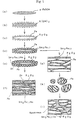
- A powder for a permanent magnet, comprising needle-like fine particles of Fe or Fe-Co alloy as a base material, a hard magnetic layer containing Fe, Sm and N on the surface of the needle-like fine particles, and a separation layer of an oxide of R outside the hard magnetic layer, R representing one or more of Nd, La, Ce, Pr, Sm and Y.
- A powder according to claim 1, in the form of a sintered body powder having a particle diameter of 10 to 100 µm.
- A powder according to claim 1 or claim 2, wherein the particles have a further separation layer of one or more of Zn, Sn and Pb on the oxide of R separation layer.
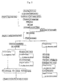
- A method for producing a powder for a permanent magnet, which comprises the steps of:coating the surface of needle-like fine particles of Fe or Fe-Co alloy having a major axis of 0.1 to 3 µm and a minor axis of 0.03 to 0.4 µm, with a hydroxide of R using a wet deposition method, R representing one or more of Nd, La, Ce, Pr, Sm and Y;subjecting the fine particles to filtration and drying;heat-treating the dried fine particles in an atmosphere of a hydrogen gas, an inert gas or a mixture thereof;coating the oxide of R-coated fine particles of Fe or Fe-Co alloy with Sm in a vacuum at a temperature of 500 to 1000°C;further heat-treating the fine particles to form a compound layer containing Fe and Sm on the surface of the needle-like fine particles; andsubjecting the heat-treated fine particles to a nitriding treatment in a nitrogen-containing gas.
- A method for producing a powder for a permanent magnet, which comprises the steps of:coating the surface of needle-like fine particles of α-FeOOH or Co-doped α-FeOOH having a major axis of 0.1 to 3 µm and a minor axis of 0.03 to 0.4 µm, with a hydroxide of R using a wet deposition method, R representing one or more of Nd, La, Ce, Pr, Sm and Y;subjecting the fine particles to filtration and drying;heat-treating the dried fine particles in an atmosphere of a hydrogen-containing gas;coating the resultant oxide of R-coated fine particles of Fe or Fe-Co alloy with Sm in a vacuum at a temperature of 500 to 1000°C;further heat-treating the fine particles to form a compound layer containing Fe and Sm on the surface of the needle-like fine particles; andsubjecting the heat-treated fine particles to a nitriding treatment in a nitrogen-containing gas.
- A method according to claim 4 or claim 5 which includes between the further heat treatment and the nitriding treatment the further steps of:compressing the fine particles in a magnetic field;sintering the compressed body at a temperature of 700 to 1000°C; andgrinding the sintered body into particles having a diameter of 10 to 100 µm.
- A method according to any one of claims 4 to 6, which includes after the nitriding treatment the further step of coating the surface of the particles with one or more of Zn, Sn and Pb.
- An anisotropic permanent magnet obtained by kneading a powder according to any one of claims 1 to 3 with a resin and hot-pressing the mixture in a magnetic field.
- An anisotropic permanent magnet obtained by hot-pressing a powder according to claim 3 whereby the Zn, Sn or Pb binds the powder particles.
Applications Claiming Priority (3)
| Application Number | Priority Date | Filing Date | Title |
|---|---|---|---|
| JP29404996 | 1996-11-06 | ||
| JP29404996A JP3647995B2 (en) | 1996-11-06 | 1996-11-06 | Powder for permanent magnet, method for producing the same and anisotropic permanent magnet using the powder |
| PCT/JP1997/004012 WO1998020507A1 (en) | 1996-11-06 | 1997-11-04 | Powder for permanent magnet, method for its production and anisotropic permanent magnet made using said powder |
Publications (3)
| Publication Number | Publication Date |
|---|---|
| EP0938105A1 EP0938105A1 (en) | 1999-08-25 |
| EP0938105A4 EP0938105A4 (en) | 1999-09-15 |
| EP0938105B1 true EP0938105B1 (en) | 2003-10-22 |
Family
ID=17802626
Family Applications (1)
| Application Number | Title | Priority Date | Filing Date |
|---|---|---|---|
| EP97909739A Expired - Lifetime EP0938105B1 (en) | 1996-11-06 | 1997-11-04 | Powder for permanent magnet, method for its production and anisotropic permanent magnet made using said powder |
Country Status (6)
| Country | Link |
|---|---|
| US (1) | US6328817B1 (en) |
| EP (1) | EP0938105B1 (en) |
| JP (1) | JP3647995B2 (en) |
| AT (1) | ATE252764T1 (en) |
| DE (1) | DE69725750T2 (en) |
| WO (1) | WO1998020507A1 (en) |
Families Citing this family (9)
| Publication number | Priority date | Publication date | Assignee | Title |
|---|---|---|---|---|
| US6710693B2 (en) * | 2001-03-23 | 2004-03-23 | Nec Tokin Corporation | Inductor component containing permanent magnet for magnetic bias and method of manufacturing the same |
| JP2002359126A (en) * | 2001-05-30 | 2002-12-13 | Nec Tokin Corp | Inductance component |
| DE10155898A1 (en) * | 2001-11-14 | 2003-05-28 | Vacuumschmelze Gmbh & Co Kg | Inductive component and method for its production |
| WO2006004998A2 (en) * | 2004-06-30 | 2006-01-12 | University Of Dayton | Anisotropic nanocomposite rare earth permanent magnets and method of making |
| JP4834869B2 (en) * | 2007-04-06 | 2011-12-14 | Necトーキン株式会社 | Permanent magnet material, permanent magnet using the same, and manufacturing method thereof |
| US8339227B2 (en) * | 2007-12-12 | 2012-12-25 | Panasonic Corporation | Inductance part and method for manufacturing the same |
| DE102012204083A1 (en) * | 2012-03-15 | 2013-09-19 | Siemens Aktiengesellschaft | Nanoparticles, permanent magnet, motor and generator |
| US9607760B2 (en) | 2012-12-07 | 2017-03-28 | Samsung Electronics Co., Ltd. | Apparatus for rapidly solidifying liquid in magnetic field and anisotropic rare earth permanent magnet |
| WO2022024920A1 (en) * | 2020-07-28 | 2022-02-03 | 国立研究開発法人産業技術総合研究所 | Anisotropic magnet microparticles and production method therefor |
Family Cites Families (7)
| Publication number | Priority date | Publication date | Assignee | Title |
|---|---|---|---|---|
| US4165232A (en) * | 1978-09-15 | 1979-08-21 | Basf Aktiengesellschaft | Manufacture of ferromagnetic metal particles essentially consisting of iron |
| US5466308A (en) * | 1982-08-21 | 1995-11-14 | Sumitomo Special Metals Co. Ltd. | Magnetic precursor materials for making permanent magnets |
| US5183515A (en) * | 1989-11-07 | 1993-02-02 | Unitika Ltd. | Fibrous anisotropic permanent magnet and production process thereof |
| JP3109637B2 (en) * | 1993-12-10 | 2000-11-20 | 日亜化学工業株式会社 | Anisotropic needle-like magnetic powder and bonded magnet using the same |
| JPH07272913A (en) * | 1994-03-30 | 1995-10-20 | Kawasaki Teitoku Kk | Permanent magnet material, and its manufacture and permanent magnet |
| JPH08203715A (en) * | 1995-01-30 | 1996-08-09 | Takahashi Yoshiaki | Raw material for permanent magnet and manufacture thereof |
| US5840375A (en) * | 1995-06-22 | 1998-11-24 | Shin-Etsu Chemical Co., Ltd. | Method for the preparation of a highly corrosion resistant rare earth based permanent magnet |
-
1996
- 1996-11-06 JP JP29404996A patent/JP3647995B2/en not_active Expired - Fee Related
-
1997
- 1997-11-04 AT AT97909739T patent/ATE252764T1/en not_active IP Right Cessation
- 1997-11-04 DE DE69725750T patent/DE69725750T2/en not_active Expired - Lifetime
- 1997-11-04 US US09/284,446 patent/US6328817B1/en not_active Expired - Fee Related
- 1997-11-04 EP EP97909739A patent/EP0938105B1/en not_active Expired - Lifetime
- 1997-11-04 WO PCT/JP1997/004012 patent/WO1998020507A1/en active IP Right Grant
Also Published As
| Publication number | Publication date |
|---|---|
| JP3647995B2 (en) | 2005-05-18 |
| US6328817B1 (en) | 2001-12-11 |
| EP0938105A1 (en) | 1999-08-25 |
| DE69725750T2 (en) | 2004-08-19 |
| WO1998020507A1 (en) | 1998-05-14 |
| EP0938105A4 (en) | 1999-09-15 |
| DE69725750D1 (en) | 2003-11-27 |
| ATE252764T1 (en) | 2003-11-15 |
| JPH10144509A (en) | 1998-05-29 |
Similar Documents
| Publication | Publication Date | Title |
|---|---|---|
| US5282904A (en) | Permanent magnet having improved corrosion resistance and method for producing the same | |
| US5454998A (en) | Method for producing permanent magnet | |
| US5716462A (en) | Magnetic material and bonded magnet | |
| US7618497B2 (en) | R-T-B based rare earth permanent magnet and method for production thereof | |
| CA2571401A1 (en) | Anisotropic nanocomposite rare earth permanent magnets and method of making | |
| EP0311049B1 (en) | Corrosion resistant rare earth metal magnet | |
| EP0249973B1 (en) | Permanent magnetic material and method for producing the same | |
| EP0553527B1 (en) | Powder material for rare earth-iron-boron based permanent magnets | |
| CN108417334A (en) | R-T-B systems sintered magnet | |
| EP0255939B1 (en) | Rare earth magnet and rare earth magnet alloy powder having high corrosion resistance | |
| EP0938105B1 (en) | Powder for permanent magnet, method for its production and anisotropic permanent magnet made using said powder | |
| JP2705985B2 (en) | MAGNETIC MATERIAL, MAGNET COMPRISING THE SAME, AND PROCESS FOR PRODUCING THEM | |
| EP0323125B1 (en) | Rare earth permanent magnet | |
| WO1988006797A1 (en) | Rare earth element-iron base permanent magnet and process for its production | |
| JPH1053844A (en) | (rare earth)-iron-boron magnetic alloy and its production and bond magnet using the (rare earth)-iron-boron magnetic alloy | |
| US5447578A (en) | Corrosion-resistant rare earth metal-transition metal series magnets and method of producing the same | |
| JPH0422010B2 (en) | ||
| EP3633696B1 (en) | Rare earth sintered magnet | |
| CN110942880B (en) | Rare earth magnet and method for producing same | |
| DE2121596A1 (en) | Hard-magnetic alloy - with high coercive force and magnetic energy and possessing one non-cubic crystalline structure | |
| CN1061163C (en) | Double-phase rare-earth-iron-boron magnetic powder and its prepn. method | |
| JPH0881741A (en) | Magnetic material and permanent magnet using the same | |
| JPH05234729A (en) | Manufacture of rare earth-iron-nitrogen magnet powder and manufacture thereof | |
| JP3469496B2 (en) | Manufacturing method of magnet material | |
| JP3488354B2 (en) | Method for producing microcrystalline permanent magnet alloy and isotropic permanent magnet powder |
Legal Events
| Date | Code | Title | Description |
|---|---|---|---|
| PUAI | Public reference made under article 153(3) epc to a published international application that has entered the european phase |
Free format text: ORIGINAL CODE: 0009012 |
|
| 17P | Request for examination filed |
Effective date: 19990602 |
|
| AK | Designated contracting states |
Kind code of ref document: A1 Designated state(s): AT DE FR GB NL SE |
|
| A4 | Supplementary search report drawn up and despatched |
Effective date: 19990730 |
|
| AK | Designated contracting states |
Kind code of ref document: A4 Designated state(s): AT DE FR GB NL SE |
|
| RIC1 | Information provided on ipc code assigned before grant |
Free format text: 6H 01F 1/06 A, 6H 01F 1/08 B, 6H 01F 1/059 B |
|
| 17Q | First examination report despatched |
Effective date: 20010427 |
|
| GRAH | Despatch of communication of intention to grant a patent |
Free format text: ORIGINAL CODE: EPIDOS IGRA |
|
| GRAS | Grant fee paid |
Free format text: ORIGINAL CODE: EPIDOSNIGR3 |
|
| GRAA | (expected) grant |
Free format text: ORIGINAL CODE: 0009210 |
|
| RAP1 | Party data changed (applicant data changed or rights of an application transferred) |
Owner name: SANTOKU CORPORATION |
|
| AK | Designated contracting states |
Kind code of ref document: B1 Designated state(s): AT DE FR GB NL SE |
|
| REG | Reference to a national code |
Ref country code: GB Ref legal event code: FG4D |
|
| REF | Corresponds to: |
Ref document number: 69725750 Country of ref document: DE Date of ref document: 20031127 Kind code of ref document: P |
|
| REG | Reference to a national code |
Ref country code: SE Ref legal event code: TRGR |
|
| ET | Fr: translation filed | ||
| PLBE | No opposition filed within time limit |
Free format text: ORIGINAL CODE: 0009261 |
|
| STAA | Information on the status of an ep patent application or granted ep patent |
Free format text: STATUS: NO OPPOSITION FILED WITHIN TIME LIMIT |
|
| 26N | No opposition filed |
Effective date: 20040723 |
|
| PGFP | Annual fee paid to national office [announced via postgrant information from national office to epo] |
Ref country code: GB Payment date: 20051024 Year of fee payment: 9 |
|
| PGFP | Annual fee paid to national office [announced via postgrant information from national office to epo] |
Ref country code: FR Payment date: 20051110 Year of fee payment: 9 |
|
| PGFP | Annual fee paid to national office [announced via postgrant information from national office to epo] |
Ref country code: SE Payment date: 20051114 Year of fee payment: 9 Ref country code: NL Payment date: 20051114 Year of fee payment: 9 |
|
| PGFP | Annual fee paid to national office [announced via postgrant information from national office to epo] |
Ref country code: AT Payment date: 20051115 Year of fee payment: 9 |
|
| PG25 | Lapsed in a contracting state [announced via postgrant information from national office to epo] |
Ref country code: AT Free format text: LAPSE BECAUSE OF NON-PAYMENT OF DUE FEES Effective date: 20061104 |
|
| PG25 | Lapsed in a contracting state [announced via postgrant information from national office to epo] |
Ref country code: SE Free format text: LAPSE BECAUSE OF NON-PAYMENT OF DUE FEES Effective date: 20061105 |
|
| PG25 | Lapsed in a contracting state [announced via postgrant information from national office to epo] |
Ref country code: NL Free format text: LAPSE BECAUSE OF NON-PAYMENT OF DUE FEES Effective date: 20070601 |
|
| EUG | Se: european patent has lapsed | ||
| GBPC | Gb: european patent ceased through non-payment of renewal fee |
Effective date: 20061104 |
|
| NLV4 | Nl: lapsed or anulled due to non-payment of the annual fee |
Effective date: 20070601 |
|
| REG | Reference to a national code |
Ref country code: FR Ref legal event code: ST Effective date: 20070731 |
|
| PG25 | Lapsed in a contracting state [announced via postgrant information from national office to epo] |
Ref country code: GB Free format text: LAPSE BECAUSE OF NON-PAYMENT OF DUE FEES Effective date: 20061104 |
|
| PG25 | Lapsed in a contracting state [announced via postgrant information from national office to epo] |
Ref country code: FR Free format text: LAPSE BECAUSE OF NON-PAYMENT OF DUE FEES Effective date: 20061130 |
|
| PGFP | Annual fee paid to national office [announced via postgrant information from national office to epo] |
Ref country code: DE Payment date: 20101119 Year of fee payment: 14 |
|
| REG | Reference to a national code |
Ref country code: DE Ref legal event code: R119 Ref document number: 69725750 Country of ref document: DE Effective date: 20130601 |
|
| PG25 | Lapsed in a contracting state [announced via postgrant information from national office to epo] |
Ref country code: DE Free format text: LAPSE BECAUSE OF NON-PAYMENT OF DUE FEES Effective date: 20130601 |