EP0937199B1 - Verfahren zum betrieb einer antriebseinheit für kraftfahrzeuge - Google Patents
Verfahren zum betrieb einer antriebseinheit für kraftfahrzeuge Download PDFInfo
- Publication number
- EP0937199B1 EP0937199B1 EP97950071A EP97950071A EP0937199B1 EP 0937199 B1 EP0937199 B1 EP 0937199B1 EP 97950071 A EP97950071 A EP 97950071A EP 97950071 A EP97950071 A EP 97950071A EP 0937199 B1 EP0937199 B1 EP 0937199B1
- Authority
- EP
- European Patent Office
- Prior art keywords
- torque
- transmission
- drive motor
- control unit
- steering gear
- Prior art date
- Legal status (The legal status is an assumption and is not a legal conclusion. Google has not performed a legal analysis and makes no representation as to the accuracy of the status listed.)
- Expired - Lifetime
Links
- 238000011017 operating method Methods 0.000 title 1
- 238000000034 method Methods 0.000 claims abstract description 25
- 230000005540 biological transmission Effects 0.000 claims description 64
- 238000004378 air conditioning Methods 0.000 claims description 5
- 230000002596 correlated effect Effects 0.000 claims 1
- 230000000875 corresponding effect Effects 0.000 claims 1
- 238000005086 pumping Methods 0.000 claims 1
- 238000011144 upstream manufacturing Methods 0.000 claims 1
- 230000007246 mechanism Effects 0.000 abstract 1
- 238000002347 injection Methods 0.000 description 8
- 239000007924 injection Substances 0.000 description 8
- 238000010586 diagram Methods 0.000 description 5
- 230000002441 reversible effect Effects 0.000 description 3
- 238000010521 absorption reaction Methods 0.000 description 2
- 230000001133 acceleration Effects 0.000 description 2
- 230000000694 effects Effects 0.000 description 2
- 239000000446 fuel Substances 0.000 description 2
- 206010000210 abortion Diseases 0.000 description 1
- 231100000176 abortion Toxicity 0.000 description 1
- 230000004913 activation Effects 0.000 description 1
- 238000002485 combustion reaction Methods 0.000 description 1
- 238000010276 construction Methods 0.000 description 1
- 230000003111 delayed effect Effects 0.000 description 1
- 230000000881 depressing effect Effects 0.000 description 1
- 230000003292 diminished effect Effects 0.000 description 1
- 230000007613 environmental effect Effects 0.000 description 1
- XDDAORKBJWWYJS-UHFFFAOYSA-N glyphosate Chemical compound OC(=O)CNCP(O)(O)=O XDDAORKBJWWYJS-UHFFFAOYSA-N 0.000 description 1
- 230000001771 impaired effect Effects 0.000 description 1
- 230000001105 regulatory effect Effects 0.000 description 1
- 230000007704 transition Effects 0.000 description 1
Images

Classifications
-
- F—MECHANICAL ENGINEERING; LIGHTING; HEATING; WEAPONS; BLASTING
- F02—COMBUSTION ENGINES; HOT-GAS OR COMBUSTION-PRODUCT ENGINE PLANTS
- F02D—CONTROLLING COMBUSTION ENGINES
- F02D45/00—Electrical control not provided for in groups F02D41/00 - F02D43/00
-
- F—MECHANICAL ENGINEERING; LIGHTING; HEATING; WEAPONS; BLASTING
- F02—COMBUSTION ENGINES; HOT-GAS OR COMBUSTION-PRODUCT ENGINE PLANTS
- F02D—CONTROLLING COMBUSTION ENGINES
- F02D41/00—Electrical control of supply of combustible mixture or its constituents
- F02D41/02—Circuit arrangements for generating control signals
- F02D41/14—Introducing closed-loop corrections
-
- F—MECHANICAL ENGINEERING; LIGHTING; HEATING; WEAPONS; BLASTING
- F02—COMBUSTION ENGINES; HOT-GAS OR COMBUSTION-PRODUCT ENGINE PLANTS
- F02D—CONTROLLING COMBUSTION ENGINES
- F02D2200/00—Input parameters for engine control
- F02D2200/02—Input parameters for engine control the parameters being related to the engine
- F02D2200/10—Parameters related to the engine output, e.g. engine torque or engine speed
- F02D2200/1006—Engine torque losses, e.g. friction or pumping losses or losses caused by external loads of accessories
Definitions
- the invention relates to a method for operating a Drive unit for motor vehicles, in particular tracked vehicles with a preferably electronic control unit torque-influencing drive motor, one Load transmitter, a transmission, and at least one other Consumers, as defined in claim 1, part 1 is.
- DE 43 04 779 A1 describes a control method a drive unit in which the drive motor torque depending on the torque flow to another Consumers in the sense of a compensation to the further Torque flow reaching consumers affected becomes.
- Such a process can be used anywhere where consumers are present, their moment of absorption is not determined solely by the engine speed. In addition to the transmission, there will be at least one other Consumers involved in the process.
- the invention is therefore based on the object Specify method for operating a drive unit with the mileage increases can be achieved without the Need to increase the transmission capacity of the transmission.
- Prerequisites are that the consumer has his torque the drive train in front of the transmission takes and the permissible input torque on Travel gear is smaller than a potentially maximum drive motor torque.
- the drive motor torque is variably capped by a value that is the sum from a permissible input torque on the transmission and corresponds to the current torque flow to the consumer.
- the meaning of "driving in front of the transmission” includes a case where a consumer (e.g. Power take-off) driven by the transmission input shaft, however, before the actual transmission part lies.
- the permissible input torque on the travel gear must not necessarily be a fixed value. If, for example the transmission capacity of a clutch that permissible input torque determined on the transmission, can it makes sense to set the permissible input torque as Function or characteristic curve depending on engine speed, hydraulic Pressure, temperatures or - with a step transmission To store the gear in the control.
- the current torque flow to the further consumers from vehicle data and / or from measured Vehicle status and / or environmental data generated Signals can be determined particularly easily. Under vehicle data in this sense are also parameters of individual Understand vehicle components. Is just as obvious also that the computer in a combined engine transmission control unit is integrated, or that individual Vehicle components (consumers) themselves with a corresponding Electronics are equipped, and their respective Recording torque as a signal, preferably on a data bus provide.
- the transmission control unit receives the for determination of the torque flow to the other consumer used Signals and a load signal from the load generator from this a signal "torque request" and transmitted this signal to the engine control unit. This controls the Drive motor so that the actual drive motor torque the current "torque request" largely corresponds.
- an appropriate actuator system such as a Injection pump used.
- the transmission control unit receives the Calculation of the torque flow to the other consumer used signals and generates a current one Signal "maximum permissible drive motor torque".
- the Engine control unit receives this generated signal from the transmission control unit and a load signal directly from Load generator and controls the drive motor in such a way that actual drive motor torque is the "maximum allowable Drive motor torque ".
- the engine control unit depends on the signal "Maximum permissible drive motor torque" an assignment load signal and actual motor control (e.g. Injection quantity).
- the area of automatic compensation depends on the load position, above which due to a Torque flow to the other consumer the actual Motor control is affected. Is this load position the full load position, must in the partial load range manually compensated by the driver. Should be an elevated Motor torque with existing torque flow to the further Consumers are not constantly available automatically it may make sense to add another Introduce condition, such as the operation a kick-down switch.
- the torque flow can be to the steering gear part advantageously by using at least one of the sizes drive gear ratio, steering gear ratio, Turning resistance coefficient, curve radius or preferably determine the steering wheel angle by calculation.
- a hydraulic fan drive with a hydraulic pump and A hydraulic motor is the use of the drive motor speed quantities or a pump power of the hydraulic pump advantageous.
- the use of a torque measuring device is also obvious at a suitable location, preferably at the point where the torque flow to the steering gear branches off, or at the transmission input.
- the automatic transmission part a powershift stage transmission, preferably in Planetary construction is.
- the use is obvious of continuously variable transmissions for the driving and / or steering gear.
- These continuously variable transmissions can, for example as a hydrodynamic transmission, hydrodynamically power split Gear or designed as a belt gear his.
- a turbocharged multi-fuel engine has the advantage that he operated in overload by increasing the boost pressure can be.
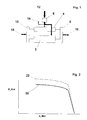
- the torque at the transmission input 12 acts on the input shaft of the input group 6, a first fixed gear ratio at the transmission input.
- the torque flow is divided into two according to the input group the paths to the transmission 2, to the steering gear 4 and in a path 14 to the auxiliary units (e.g. fan drive).
- the output torques of the travel gear and the steering gear are added up in the summation gears 8, 10. Each there are different torque flows depending on the driving condition 16, 18 to the two (left and right side) Outputs that are not shown in Fig. 1.
- the steering gear turns on considerable portion of the supplied torque 12 is branched off, whereby initially less torque is reached to the transmission 2.
- the method according to the invention now provides, depending on Torque flow to the steering gear 4 and to the auxiliary units 14 more torque at the transmission input by influencing engine torque 12 to generate.
- the second full-load characteristic curve 22 schematically shows two full-load torque characteristics a drive motor plotted against the engine speed (n_Mot).
- the first full-load characteristic curve 20 applies to straight-ahead driving or without another consumer and fulfills the condition that the allowable input torque of the transmission is not exceeded.
- the second shown in dashed lines The full load characteristic applies when there are additional consumers at least the moment difference of the represented Branch off lines in front of the transmission. May the second Full load characteristic curve 22 can be kept permanently by the engine this means that the engine is constantly moving straight ahead is operated throttled. Overload operation of the engine is available if only the first full-load characteristic 20 can be held permanently by the motor, but the motor can realize the full load characteristic curve 22 at short notice.
- FIGS. 3 and 4 schematically show two options, such as an inventive Method with a transmission control unit 24 and an engine control unit 26 can be configured.
- the Transmission control unit 3 receives the Transmission control unit 24 a load signal (accelerator pedal position 32) and a signal "steering wheel angle" 30.
- the transmission control unit determines the torque flow from these signals to the steering gear and adds this to one of the accelerator pedal positions corresponding torque request.
- the total value is converted to a torque request signal 34 and transmitted to the engine control unit.
- the engine control unit generates this torque request 34 the signal injection time 36, which from a fuel injection pump 28 is received.
- This configuration is particularly suitable for one automatic compensation of the torque flow to the steering gear in the entire load range.
- the second embodiment according to FIG. 4 differs differ from the first in that the load signal (Accelerator pedal position 32) directly from the engine control unit is received, and the transmission control unit from the signal “Steering wheel angle" 30 a signal “maximum permissible drive motor torque” 38 generated. This will also received by the engine control unit.
- This embodiment of the method is particularly suitable good if the compensation only in the high load range should be done automatically.
- the driver must be in the partial load range the torque absorbed by the steering gear manually compensate if the vehicle does not slow down should.
Landscapes
- Engineering & Computer Science (AREA)
- Chemical & Material Sciences (AREA)
- Combustion & Propulsion (AREA)
- Mechanical Engineering (AREA)
- General Engineering & Computer Science (AREA)
- Control Of Transmission Device (AREA)
- Control Of Driving Devices And Active Controlling Of Vehicle (AREA)
- Non-Deflectable Wheels, Steering Of Trailers, Or Other Steering (AREA)
Abstract
Description
Die Aufnahmeleistung einer Klimaanlage ist im Verhältnis zur benötigten Motorleistung beispielsweise bei einem PKW bei Konstantfahrt in der Ebene nicht unerheblich. In der Regel macht sich das Zuschalten des Klimakompressors durch einen unerwünschten kleinen Geschwindigkeitsverlust bemerkbar, der vom Fahrer durch weiteres Niedertreten des Fahrpedals ausgeglichen werden muß. Eine erfindungsgemäße automatische Kompensation führt hier zu einer Fahrerentlastung. Auch die Möglichkeit, bei eingeschaltetem Klimakompressor ein höheres maximales Antriebsmotordrehmoment zuzulassen ist bei einem Fahrzeug vorteilhaft, bei dem der Antriebsmotor grundsätzlich ein höheres Moment abgeben könnte, als vom Getriebe übertragen werden kann.
- Fig. 1:
- ein Drehmomentenfluß - Schema eines Kettenfahrzeuggetriebes
- Fig. 2:
- zwei Vollastkennlinien in einem Motormomentendiagramm
- Fig. 3:
- ein erstes Blockdiagramm
- Fig. 4:
- ein weiteres Blockdiagramm
- 2
- Fahrgetriebe
- 4
- Lenkgetriebe
- 6
- Eintriebsgruppe
- 8
- Summierungsgetriebe außen
- 10
- Summierungsgetriebe innen
- 12
- Moment am Getriebeeingang
- 14
- Moment zu den Nebenaggregaten (Lüfterantrieb)
- 16
- Moment am äußeren Abtrieb
- 18
- Moment am inneren Abtrieb
- 20
- Vollastlinie ohne Drehmomentenfluß zu dem weiteren Verbraucher
- 22
- Vollastlinie mit Drehmomentenfluß zu dem weiteren Verbraucher
- 24
- Getriebesteuereinheit
- 26
- Motorsteuereinheit
- 28
- Einspritzpumpe
- 30
- Lenkradwinkel
- 32
- Fahrpedalstellung
- 34
- Signal "Drehmomentanforderung"
- 36
- Signal "Einspritzzeit"
- 38
- Signal "maximal zulässiges Antriebsmotordrehmoment
Claims (11)
- Verfahren zum Betrieb einer Antriebseinheit für Kraftfahrzeuge insbesondere Kettenfahrzeuge mit einem durch eine vorzugsweise elektronische Steuereinheit (26) drehmomentbeeinflußbaren Antriebsmotor, einem Lastgeber, einem Fahrgetriebe (2), und mindestens einem weiteren Verbraucher (4), wobei abhängig vom aktuellen Drehmomentenfluß zu dem weiteren Verbraucher das Antriebsmotordrehmoment oberhalb einer bestimmten Stellung des Lastgebers durch die Steuereinheit (26) im Sinne einer mindestens teilweisen Kompensation des zu dem weiteren Verbraucher gelangenden Drehmomentenfluß beeinflußt wird, dadurch gekennzeichnet, daß der Drehmomentenfluß zu dem weiteren Verbraucher trieblich vor dem Fahrgetriebe abzweigt, daß das zulässige Eingangsdrehmoment am Fahrgetriebe kleiner ist, als ein potentiell maximales Antriebsmotordrehmoment, und daß das Antriebsmotordrehmoment variabel nach oben begrenzt wird durch einen Wert, der der Summe aus einem zulässigem Eingangsdrehmoment am Fahrgetriebe und dem aktuellen Drehmomentenfluß zu dem Verbraucher entspricht, um bei geringem Drehmomentenfluß zu dem weiteren Verbraucher eine Überlastung des Fahrgetriebes zu vermeiden.
- Verfahren nach Anspruch 1, dadurch gekennzeichnet, daß der aktuelle Drehmomentenfluß zu dem weiteren Verbraucher mittels eines vorzugsweise in einer elektronischen Motor- (26) oder Getriebesteuereinheit (24) integrierten Rechners aus Fahrzeugdaten und/oder aus gemessenen Fahrzeugzustands- und/oder Umgebungsdaten erzeugten Signalen (30) ermittelt wird.
- Verfahren nach Anspruch 2, dadurch gekennzeichnet, daß die Getriebesteuereinheit (24) die zur Ermittlung des Drehmomentenfluß zu dem weiteren Verbraucher verwendeten Signale (30) und ein Lastsignal (32) des Lastgebers empfängt, hieraus ein Signal "Drehmomentanforderung" (34) generiert, dieses Signal an die Motorsteuereinheit (26) übermittelt, und die Motorsteuereinheit (26) den Antriebsmotor derart ansteuert, daß das tatsächliche Antriebsmotordrehmoment der aktuellen "Drehmomentanforderung" (34) weitgehend entspricht.
- Verfahren nach Anspruch 2, dadurch gekennzeichnet, daß die Getriebesteuereinheit (24) die zur Berechnung des Drehmomentenfluß zu dem weiteren Verbraucher verwendeten Signale (30) empfängt, hieraus ein aktuelles Signal "maximal zulässiges Antriebsmotordrehmoment" (38) generiert, die Motorsteuereinheit (26) dieses generierte Signal von der Getriebesteuereinheit (24) und ein Lastsignal (32) direkt vom Lastgeber empfängt und den Antriebsmotor derart ansteuert, daß das tatsächliche Antriebsmotordrehmoment das "maximal zulässige Antriebsmotordrehmoment" (38) nicht übersteigt.
- Verfahren nach einem der Ansprüche 1 bis 4, dadurch gekennzeichnet, daß der Antriebsmotor kurzzeitig im Sinne eine Überlastbetriebs betrieben wird, insbesondere bei vorhandenem Drehmomentenfluß zu dem weiteren Verbraucher.
- Verfahren nach einem der Ansprüche 1 bis 5, dadurch gekennzeichnet, daß das Kraftfahrzeug ein Kettenfahrzeug, das Fahrgetriebe der automatische Fahrgetriebeteil (2) eines Überlagerungs-Lenkgetriebes, der Lastgeber ein Fahrpedal, und ein weiterer Verbraucher ein Lenkgetriebeteil (4) des Überlagerungs-Lenkgetriebes oder ein hydraulischer Lüfterantrieb ist.
- Verfahren nach Anspruch 6, dadurch gekennzeichnet, daß zur Ermittlung des Drehmomentenfluß zum Lenkgetriebeteil mindestens eine der Größen:oder mindestens eine mit den genannten Größen in mathematisch oder physikalischen Zusammenhang bringbare Größe verwendet wird.Fahrgetriebeübersetzung,Lenkgetriebeübersetzung,Wendewiderstandsbeiwert,Kurvenradius,Lenkradwinkel (30),Antriebsmotordrehzahl,Pumpenleistung,
- Verfahren nach Anspruch 6 oder 7, dadurch gekennzeichnet, daß der automatische Fahrgetriebeteil (2) ein lastschaltbares Stufengetriebe ist.
- Verfahren nach einem der Ansprüche 6 bis 8 dadurch gekennzeichnet, daß der Lenkgetriebeteil (4) ein lastschaltbares Stufengetriebe (Mehrradien-Lenkgetriebe) ist.
- Verfahren nach einem der Ansprüche 1 bis 9, dadurch gekennzeichnet, daß als Antriebsmotor ein vorzugsweise turboaufgeladener Mehrstoffmotor vorgesehen ist.
- Verfahren nach einem der Ansprüche 1 bis 10, dadurch gekennzeichnet, daß als weiterer Verbraucher eine Klimaanlage und/oder ein Nebenabtrieb vorgesehen ist.
Applications Claiming Priority (3)
| Application Number | Priority Date | Filing Date | Title |
|---|---|---|---|
| DE19646069 | 1996-11-08 | ||
| DE19646069A DE19646069A1 (de) | 1996-11-08 | 1996-11-08 | Verfahren zum Betrieb einer Antriebseinheit für Kraftfahrzeuge |
| PCT/EP1997/006047 WO1998021464A1 (de) | 1996-11-08 | 1997-11-03 | Verfahren zum betrieb einer antriebseinheit für kraftfahrzeuge |
Publications (2)
| Publication Number | Publication Date |
|---|---|
| EP0937199A1 EP0937199A1 (de) | 1999-08-25 |
| EP0937199B1 true EP0937199B1 (de) | 2001-04-18 |
Family
ID=7811014
Family Applications (1)
| Application Number | Title | Priority Date | Filing Date |
|---|---|---|---|
| EP97950071A Expired - Lifetime EP0937199B1 (de) | 1996-11-08 | 1997-11-03 | Verfahren zum betrieb einer antriebseinheit für kraftfahrzeuge |
Country Status (5)
| Country | Link |
|---|---|
| US (1) | US6155955A (de) |
| EP (1) | EP0937199B1 (de) |
| KR (1) | KR100462310B1 (de) |
| DE (2) | DE19646069A1 (de) |
| WO (1) | WO1998021464A1 (de) |
Families Citing this family (9)
| Publication number | Priority date | Publication date | Assignee | Title |
|---|---|---|---|---|
| US6511399B2 (en) * | 2001-04-25 | 2003-01-28 | General Motors Corporation | Torque and power control in a powertrain |
| DE10242230A1 (de) * | 2002-09-12 | 2003-10-30 | Daimler Chrysler Ag | Verfahren zum Betreiben eines Fahrzeugs mit mehreren Aggregaten |
| JP4099653B2 (ja) * | 2002-11-08 | 2008-06-11 | 三菱ふそうトラック・バス株式会社 | 機械式変速機の変速制御装置 |
| DE10344711A1 (de) * | 2003-09-26 | 2005-04-14 | Zf Friedrichshafen Ag | Elektrisches Antriebssystem für ein Fahrzeug mit Rutschlenkung |
| DE102004027063A1 (de) * | 2004-06-03 | 2005-12-22 | Zf Friedrichshafen Ag | Verfahren zur optimierten Erfassung des Getriebeeingangsmomentes in Fahrzeugen, die mit motorseitigen Nebenaggregaten ausgestattet sind |
| DE102004027062A1 (de) * | 2004-06-03 | 2005-12-22 | Zf Friedrichshafen Ag | Verfahren zum Verhindern des Schaltpendelns in Grenzsteigungssituationen für ein Kraftfahrzeug mit einem Automatgetriebe |
| US8414449B2 (en) * | 2007-11-04 | 2013-04-09 | GM Global Technology Operations LLC | Method and apparatus to perform asynchronous shifts with oncoming slipping clutch torque for a hybrid powertrain system |
| DE102010029373A1 (de) * | 2010-05-27 | 2011-12-01 | Zf Friedrichshafen Ag | Verfahren zum Verhindern von Pendelschaltungen bei einem Fahrzeug umfassend ein Stufenautomatgetriebe |
| DE102017221977B4 (de) * | 2017-12-06 | 2022-09-29 | Zf Friedrichshafen Ag | Leistungslimitierung der Getriebeleistung über externe Schnittstelle |
Family Cites Families (22)
| Publication number | Priority date | Publication date | Assignee | Title |
|---|---|---|---|---|
| FI54018C (fi) * | 1976-11-19 | 1978-09-11 | Rauma Repola Oy | Belastningskompenserad hydrostatisk effekttransmissionsanordning |
| DE3242299A1 (de) * | 1982-11-16 | 1984-05-17 | Thyssen Industrie Ag, 4300 Essen | Arbeitsverfahren und zusatzvorrichtung fuer lenkgetriebe von gleiskettenfahrzeugen |
| JPS61129332A (ja) * | 1984-11-28 | 1986-06-17 | Honda Motor Co Ltd | エンジンで駆動される車両用補機類の制御装置 |
| WO1988003097A1 (fr) * | 1986-10-31 | 1988-05-05 | Zahnradfabrik Friedrichshafen Ag | Systeme de transmission pour vehicules a moteur |
| US4724810A (en) * | 1987-02-13 | 1988-02-16 | General Motors Corporation | Engine idle speed control with feedforward power adjustment |
| DD261298A1 (de) * | 1987-05-26 | 1988-10-26 | Fortschritt Veb K | Anordnung und verfahren zur motorregelung bei selbstfahrenden arbeitsmaschinen |
| EP0389500B1 (de) * | 1987-10-09 | 1991-12-27 | ZF FRIEDRICHSHAFEN Aktiengesellschaft | Überlagerungslenkgetriebe für gleiskettenfahrzeuge |
| DE3739389A1 (de) * | 1987-11-20 | 1989-06-01 | Rexroth Mannesmann Gmbh | Antriebssystem |
| JPH0663463B2 (ja) * | 1989-09-27 | 1994-08-22 | マツダ株式会社 | エンジンの燃料制御装置 |
| US5000277A (en) * | 1989-11-30 | 1991-03-19 | General Motors Corporation | Hydrostatic steering control for a tracked vehicle |
| DE4112982C2 (de) * | 1991-04-20 | 1998-03-19 | Renk Ag | Antriebs- und Bremsanlage für ein Vollkettenfahrzeug |
| DE4141947C2 (de) * | 1991-12-19 | 2002-02-07 | Bosch Gmbh Robert | Steuersystem für eine Antriebseinheit in einem Flugzeug |
| DE4200806C1 (en) * | 1992-01-15 | 1993-01-28 | Mercedes-Benz Aktiengesellschaft, 7000 Stuttgart, De | Speed control for IC engine auxiliary - determines power requirement and raises idling rpm if necessary |
| DE4304779B4 (de) * | 1992-06-20 | 2005-11-24 | Robert Bosch Gmbh | Vorrichtung zur Steuerung des von einer Antriebseinheit eines Fahrzeugs abzugebenden Drehmoments |
| DE4239711B4 (de) * | 1992-11-26 | 2005-03-31 | Robert Bosch Gmbh | Verfahren und Vorrichtung zur Steuerung eines Fahrzeugs |
| US5457633A (en) * | 1994-02-24 | 1995-10-10 | Caterpillar Inc. | Apparatus for limiting horsepower output of an engine and method of operating same |
| DE19512637A1 (de) * | 1995-04-05 | 1996-10-10 | Claas Ohg | Antriebseinheit, Verfahren zu deren Steuerung und Verwendung derselben |
| US5666917A (en) * | 1995-06-06 | 1997-09-16 | Ford Global Technologies, Inc. | System and method for idle speed control |
| DE19536038B4 (de) * | 1995-09-28 | 2007-08-16 | Robert Bosch Gmbh | Verfahren und Vorrichtung zur Steuerung der Antriebseinheit eines Kraftfahrzeugs |
| US5577474A (en) * | 1995-11-29 | 1996-11-26 | General Motors Corporation | Torque estimation for engine speed control |
| SE9600454L (sv) * | 1996-02-07 | 1997-04-14 | Scania Cv Ab | Förfarande för korrigering av motormomentet vid växling |
| US5947084A (en) * | 1998-03-04 | 1999-09-07 | Ford Global Technologies, Inc. | Method for controlling engine idle speed |
-
1996
- 1996-11-08 DE DE19646069A patent/DE19646069A1/de not_active Withdrawn
-
1997
- 1997-11-03 US US09/269,374 patent/US6155955A/en not_active Expired - Fee Related
- 1997-11-03 DE DE59703400T patent/DE59703400D1/de not_active Expired - Lifetime
- 1997-11-03 EP EP97950071A patent/EP0937199B1/de not_active Expired - Lifetime
- 1997-11-03 KR KR10-1999-7004091A patent/KR100462310B1/ko not_active Expired - Fee Related
- 1997-11-03 WO PCT/EP1997/006047 patent/WO1998021464A1/de not_active Ceased
Also Published As
| Publication number | Publication date |
|---|---|
| KR100462310B1 (ko) | 2004-12-16 |
| KR20000053156A (ko) | 2000-08-25 |
| WO1998021464A1 (de) | 1998-05-22 |
| DE19646069A1 (de) | 1998-05-14 |
| US6155955A (en) | 2000-12-05 |
| EP0937199A1 (de) | 1999-08-25 |
| DE59703400D1 (de) | 2001-05-23 |
Similar Documents
| Publication | Publication Date | Title |
|---|---|---|
| DE19922740B4 (de) | System zum Steuern des Motorbremsmoments im Schubbetrieb | |
| DE69929845T2 (de) | Unabhängige Steuerung von Dauerbremsen auf Getriebeseite und Motorseite während des Gangschaltens | |
| DE68924962T2 (de) | Elektronisch geregeltes, anpassbares selbsttätig schaltendes getriebesystem. | |
| EP0588828B1 (de) | Verfahren zum steuern eines stufenlosen getriebes | |
| EP0956468B1 (de) | Einrichtung zum auswerten von fahrzeug-, antriebs- und betriebsparametern um eine übersetzung eines getriebes zu steuern | |
| EP0907524B1 (de) | Verfahren und vorrichtung zur steuerung des antriebsstrangs eines kraftfahrzeugs | |
| EP1448403A1 (de) | System und verfahren zur vorgabe eines motordrehmomentes und einer getriebeübersetzung bei einem fahrzeug mit kontinuierlich verstellbarem getriebe | |
| DE112008002603B4 (de) | Automatikgetriebesteuereinrichtung eines Automatikgetriebes und Verfahren für das beschleunigte Aufwärmen einer Verbrennungskraftmaschine | |
| DE102006013326A1 (de) | Gangwechsel-Steuervorrichtung für ein Hybridfahrzeug | |
| DE3321948C2 (de) | ||
| EP1248021A1 (de) | Elektronische Getriebeeinheit zur Gangwechselsteuerung in einem Kraftfahrzeug | |
| EP1855021B1 (de) | Verfahren zum Anfahren bei Brennkraftmaschinen mit Doppelkupplungsgetriebe | |
| DE69425201T2 (de) | Schaltsteuerung für ein automatisches Getriebe | |
| DE112009004356B4 (de) | Steuervorrichtung und Steuerverfahren für Fahrzeuge | |
| DE4020201C2 (de) | Einrichtung zur Steuerung der Gangschaltung eines automatischen Getriebes | |
| DE3735246A1 (de) | Antriebseinrichtung fuer ein kraftfahrzeug | |
| DE19714946A1 (de) | Verfahren und Vorrichtung zum Steuern der Bergabfahrt eines Fahrzeugs | |
| DE102010030495B3 (de) | Verfahren zum Betreiben einer Getriebeeinrichtung | |
| EP0937199A1 (de) | Verfahren zum betrieb einer antriebseinheit für kraftfahrzeuge | |
| EP0911206A2 (de) | Verfahren zum Schalten eines Automatikgetriebes in einem Fahrzeug | |
| DE60210902T2 (de) | Steuereinrichtung einer automatischen Kupplung | |
| DE102005037032A1 (de) | Die Bremsen betätigendes Getriebesteuersystem | |
| DE60316785T2 (de) | Antriebsstrang für kraftfahrzeug | |
| EP1836416A1 (de) | Verfahren zum anpassen einer betriebsweise eines automatischen wechselgetriebes | |
| DE102012216229A1 (de) | Antriebsstrang und Verfahren zum Betreiben eines Antriebsstrangs eines Fahrzeugs mit zwei entgegengesetzten Fahrtrichtungen |
Legal Events
| Date | Code | Title | Description |
|---|---|---|---|
| PUAI | Public reference made under article 153(3) epc to a published international application that has entered the european phase |
Free format text: ORIGINAL CODE: 0009012 |
|
| 17P | Request for examination filed |
Effective date: 19990305 |
|
| AK | Designated contracting states |
Kind code of ref document: A1 Designated state(s): DE FR GB IT |
|
| 17Q | First examination report despatched |
Effective date: 20000331 |
|
| GRAG | Despatch of communication of intention to grant |
Free format text: ORIGINAL CODE: EPIDOS AGRA |
|
| GRAG | Despatch of communication of intention to grant |
Free format text: ORIGINAL CODE: EPIDOS AGRA |
|
| GRAH | Despatch of communication of intention to grant a patent |
Free format text: ORIGINAL CODE: EPIDOS IGRA |
|
| GRAH | Despatch of communication of intention to grant a patent |
Free format text: ORIGINAL CODE: EPIDOS IGRA |
|
| ITF | It: translation for a ep patent filed | ||
| GRAA | (expected) grant |
Free format text: ORIGINAL CODE: 0009210 |
|
| AK | Designated contracting states |
Kind code of ref document: B1 Designated state(s): DE FR GB IT |
|
| GBT | Gb: translation of ep patent filed (gb section 77(6)(a)/1977) |
Effective date: 20010501 |
|
| REF | Corresponds to: |
Ref document number: 59703400 Country of ref document: DE Date of ref document: 20010523 |
|
| ET | Fr: translation filed | ||
| REG | Reference to a national code |
Ref country code: GB Ref legal event code: IF02 |
|
| PLBE | No opposition filed within time limit |
Free format text: ORIGINAL CODE: 0009261 |
|
| STAA | Information on the status of an ep patent application or granted ep patent |
Free format text: STATUS: NO OPPOSITION FILED WITHIN TIME LIMIT |
|
| 26N | No opposition filed | ||
| PGFP | Annual fee paid to national office [announced via postgrant information from national office to epo] |
Ref country code: GB Payment date: 20051102 Year of fee payment: 9 |
|
| PGFP | Annual fee paid to national office [announced via postgrant information from national office to epo] |
Ref country code: FR Payment date: 20051108 Year of fee payment: 9 |
|
| PGFP | Annual fee paid to national office [announced via postgrant information from national office to epo] |
Ref country code: IT Payment date: 20061130 Year of fee payment: 10 |
|
| GBPC | Gb: european patent ceased through non-payment of renewal fee |
Effective date: 20061103 |
|
| REG | Reference to a national code |
Ref country code: FR Ref legal event code: ST Effective date: 20070731 |
|
| PG25 | Lapsed in a contracting state [announced via postgrant information from national office to epo] |
Ref country code: GB Free format text: LAPSE BECAUSE OF NON-PAYMENT OF DUE FEES Effective date: 20061103 |
|
| PG25 | Lapsed in a contracting state [announced via postgrant information from national office to epo] |
Ref country code: FR Free format text: LAPSE BECAUSE OF NON-PAYMENT OF DUE FEES Effective date: 20061130 |
|
| PG25 | Lapsed in a contracting state [announced via postgrant information from national office to epo] |
Ref country code: IT Free format text: LAPSE BECAUSE OF NON-PAYMENT OF DUE FEES Effective date: 20071103 |
|
| PGFP | Annual fee paid to national office [announced via postgrant information from national office to epo] |
Ref country code: DE Payment date: 20121031 Year of fee payment: 16 |
|
| REG | Reference to a national code |
Ref country code: DE Ref legal event code: R119 Ref document number: 59703400 Country of ref document: DE Effective date: 20140603 |
|
| PG25 | Lapsed in a contracting state [announced via postgrant information from national office to epo] |
Ref country code: DE Free format text: LAPSE BECAUSE OF NON-PAYMENT OF DUE FEES Effective date: 20140603 |