EP0936077A2 - Schreibträgermechanismus, Druckgerät mit diesem Schreibträgermechanismus und Verfahren zur Steuerung des Druckgerätes - Google Patents
Schreibträgermechanismus, Druckgerät mit diesem Schreibträgermechanismus und Verfahren zur Steuerung des Druckgerätes Download PDFInfo
- Publication number
- EP0936077A2 EP0936077A2 EP99102678A EP99102678A EP0936077A2 EP 0936077 A2 EP0936077 A2 EP 0936077A2 EP 99102678 A EP99102678 A EP 99102678A EP 99102678 A EP99102678 A EP 99102678A EP 0936077 A2 EP0936077 A2 EP 0936077A2
- Authority
- EP
- European Patent Office
- Prior art keywords
- platen
- print head
- recording medium
- printing
- guide
- Prior art date
- Legal status (The legal status is an assumption and is not a legal conclusion. Google has not performed a legal analysis and makes no representation as to the accuracy of the status listed.)
- Granted
Links
Images





Classifications
-
- B—PERFORMING OPERATIONS; TRANSPORTING
- B41—PRINTING; LINING MACHINES; TYPEWRITERS; STAMPS
- B41J—TYPEWRITERS; SELECTIVE PRINTING MECHANISMS, i.e. MECHANISMS PRINTING OTHERWISE THAN FROM A FORME; CORRECTION OF TYPOGRAPHICAL ERRORS
- B41J11/00—Devices or arrangements of selective printing mechanisms, e.g. ink-jet printers or thermal printers, for supporting or handling copy material in sheet or web form
- B41J11/0045—Guides for printing material
- B41J11/005—Guides in the printing zone, e.g. guides for preventing contact of conveyed sheets with printhead
-
- B—PERFORMING OPERATIONS; TRANSPORTING
- B41—PRINTING; LINING MACHINES; TYPEWRITERS; STAMPS
- B41J—TYPEWRITERS; SELECTIVE PRINTING MECHANISMS, i.e. MECHANISMS PRINTING OTHERWISE THAN FROM A FORME; CORRECTION OF TYPOGRAPHICAL ERRORS
- B41J11/00—Devices or arrangements of selective printing mechanisms, e.g. ink-jet printers or thermal printers, for supporting or handling copy material in sheet or web form
- B41J11/02—Platens
- B41J11/04—Roller platens
-
- B—PERFORMING OPERATIONS; TRANSPORTING
- B41—PRINTING; LINING MACHINES; TYPEWRITERS; STAMPS
- B41J—TYPEWRITERS; SELECTIVE PRINTING MECHANISMS, i.e. MECHANISMS PRINTING OTHERWISE THAN FROM A FORME; CORRECTION OF TYPOGRAPHICAL ERRORS
- B41J11/00—Devices or arrangements of selective printing mechanisms, e.g. ink-jet printers or thermal printers, for supporting or handling copy material in sheet or web form
- B41J11/20—Platen adjustments for varying the strength of impression, for a varying number of papers, for wear or for alignment, or for print gap adjustment
Definitions
- the present invention relates to printing devices and more particularly to printing devices with a platen mechanism, and a method of controlling the printing device.
- the gap between the print head and the platen is one of the key factors that determine print quality. If the gap is too large, the print head loses its proper distance for printing on the surface of a printing sheet. This results in blur and deformation of printed characters. With ink jet printers, if the gap is excessively large, an error of the ink drop arrival position caused by an error of the ejecting angle is enlarged, so that the print quality is also deteriorated. For this reason, to secure a high print quality, the platen-to- print head gap should be reduced by locating the platen as close to the print head as possible in a state that the platen is opposite the print head.
- a printing sheet is transported from the sheet supply side to a printing region by a transporting mechanism, such as rollers, through a sheet transport path.
- a transporting mechanism such as rollers
- the height of the inner space within the transport path is large enough to allow the printing sheet to smoothly move therethrough, thereby preventing the sheet from being jammed in the transport path. Accordingly, the printing sheet must be inserted in a narrower gap in the printing region from the large enough transport path. As a result, the leading edge of the sheet hits the platen or a member near to it, possibly causing a paper jam.
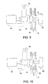
- a platen 81 is disposed opposite a print head 80, which is horizontally movable.
- the platen 81 consists of a plate-like member having a length corresponding to a movable range of the print head 80.
- the platen 81 is fastened to a support member 83, which may be turned about a shaft 82.
- the support member 83 is mechanically coupled with a solenoid plunger 84. When driven by the plunger 84, the support member 83 and hence the platen 81 are moved to and from the print head 80.
- the platen 81 In a print mode of the printer, the platen 81 is moved toward the print head 80 and its end face is positioned in a sheet transport path 85. Accordingly, a reduced gap G is set up between the platen 81 and the print head 80 (Fig. 9).
- the platen 81 In a sheet insertion mode of the printer in which a sheet is inserted into a printing region (including a portion of the transport path 85 located between the platen 81 and the print head 80), the platen 81 is retracted from the transport path 85, and hence its end face is moved apart from the print head 80 and the gap G is increased. Under this condition, the printing sheet P may enter the printing location smoothly or without any interruption.
- This conventional platen mechanism suffers from problems.
- the entirety of the combination of the platen 81 and the support member 83 is pivoted by the plunger 84.
- exactness is required for the dimensions of the related parts.
- a large space is required between the opening of the transport path 85 and the platen 81. The moving sheet is frequently caught by the large space, resulting in a paper jam.
- the platen 81 needs to be stable when it receives an impact from the print head 80. To this end, the output power of the plunger 84 must be large.
- JP-A-8-11365 Another prior art platen mechanism is disclosed in JP-A-8-11365.
- the gap between the print head and the platen is adjusted such that the gap is increased in the sheet insertion mode, and decreased in the print mode.
- An eccentrically mounted cylindrical platen is rotated to adjust the gap.
- the radius of the movement of the cylindrical platen is larger than that of the platen per se, so that a large gap is created between the platen and the guide wall. This large gap can easily catch the leading edge of the printing sheet, causing a paper jam.
- the present invention aims at providing a platen mechanism in use with a printing device which, in the print mode, keeps the gap in the printing region constant, and, in the sheet insertion mode, allows a sheet to smoothly pass the gap without any adverse effect on the sheet transporting speed.
- a platen mechanism disposed opposite a print head, is provided for supporting a recording medium.
- the platen mechanism includes a guide wall for guiding the recording medium to the print head, a platen which is rotatable about a shaft substantially parallel to the guide wall and has a support portion and a guide portion.
- the support portion projects from the guide wall to support the recording medium to the print head.
- the guide portion is substantially continuous to the guide wall to smoothly guide the recording medium being transported.
- a platen drive mechanism rotates the platen so that the support portion or the guide portion selectively confronts the print head.
- the platen when the printing device is in a print mode, the platen is turned to confront the support portion of the platen with the print head, and it serves as a platen. In this case, a force applied from the print head (such as a dot matrix or other impact print head) to the platen may be received by the rotary shaft of the platen.
- the platen is immovable and stable printing is ensured.
- the printing device is in a medium transporting mode
- the recording medium passes through a printing region (including a portion of the transport path located between the platen and the print head), the platen is turned to confront the guide portion of the platen with the print head.
- the guide portion is substantially continuous to the guide wall, so that the recording medium being transported is smoothly guided. The result is to prevent a variation of the transporting speed of the recording medium.
- the platen mechanism may comprise an urging member which urges the recording medium apart from the print head and supports the recording medium at a predetermined distance from the print head in cooperation with the support portion of the platen.
- the guide portion of the platen is preferably positioned apart from the urging member when the guide portion is opposite the print head.
- the recording medium advances without any collision and hence is free from the transporting speed variation caused by the collision of the recording medium.
- the guide portion of the platen matches the ends of the guide wall.
- the guide portion of the platen is disposed with respect to the guide walls.
- a minimum gap is present between each end of the guide portion and the end of the corresponding guide wall. The minimum gap allows the platen to move angularly. With this unique mechanical feature, there is less chance that the recording medium hits the guide portion of the platen, and hence the medium transportation speed is not varied.
- the platen includes an introducing surface for introducing the recording medium from the end of the guide wall to the support portion when the support portion confronts the print head.
- Use of the introducing surface allows the recording medium to smoothly pass through the printing region in a print ready state (the support portion of the platen confronts the print head), where a variation of the transporting speed of the recording medium offers no problem.
- a printing device can comprise a pair of rollers for transporting the recording medium when the print head prints on the recording medium, roller-pair drive mechanism for moving the paired rollers to and from each other, and interlinking mechanism for mechanically linking the platen drive mechanism to the roller-pair drive mechanism such that when the platen drive mechanism moves the platen to the first position, the roller-pair drive mechanism moves the paired rollers to each other to bring them into contact with each other, and when the platen drive mechanism moves the platen to the second position, the roller-pair drive mechanism moves the paired rollers apart from each other.
- the printing device reliably transports the recording medium in a print mode, and retracts the platen while at the same time moves the paired rollers out of the transport path.
- the printing device thus arranged realizes a quick sheet processing, easy control and reduction of the number of required drive sources.
- the platen drive mechanism can include a drive shaft, a clutch mechanism for intermittently transmitting a drive force from the drive shaft to the platen, and a trigger mechanism for setting up a coupling state of the clutch mechanism at a predetermined timing, and a decoupling state of the clutch mechanism in accordance with a predetermined quantity of rotation of the platen.
- a printing device in another embodiment, includes a print head for printing on a recording medium, a detector for reading information on the recording medium, a sheet transporting mechanism for transporting the recording medium in front of the print head and the detector, and a guide wall for guiding the recording medium being transported by the transporting mechanism to the print head.
- a platen is disposed opposite the print head and movable to a first position where the support portion thereof is projected from the guide wall to support the recording medium to the print head, and to a second position where the guide portion thereof is substantially continuous to the guide wall to smoothly guide the recording medium being transported.
- a platen drive mechanism can drive the platen to move to selectively the first or second position.
- a controller to control the platen drive mechanism to move to the first position when printing on the recording medium by the print head, and to move to the second position when reading information by the detector.
- the printing device thus constructed exactly sets the platen to predetermined positions in a print mode and a sheet transporting mode.
- the platen disposed confronting the print head is rotatable about a shaft substantially parallel to the guide walls and includes a support portion and a guide portion.
- the support portion is projected from the guide wall to support the recording medium to the print head.
- the guide portion is substantially continuous to the guide wall to smoothly guide the recording medium being transported therethrough.
- the combination of the controller and the platen completely removes a variation of the sheet transporting speed when information is read out of the recording medium.
- the detector may be a magnetic head for reading information from the recording medium.
- the operation of reading the MICR characters is sensitive to the speed variation.
- Use of the magnetic head is very useful, in this respect.
- Other types of readers, such as optical character or magnetic stripe readers, can also be used.
- the printing device may further comprise a command interpreter for interpreting a control command received from a host device connecting to the printing device, wherein the controller moves the platen to the second position when the command interpreter interprets a predetermined command to require the detector to read information.
- a command interpreter for interpreting a control command received from a host device connecting to the printing device, wherein the controller moves the platen to the second position when the command interpreter interprets a predetermined command to require the detector to read information.
- the invention further provides a method of controlling a printing device comprising the steps of: transporting a recording medium on and along guide walls, supporting the recording medium to a print head in a state that a platen is projected to a support position, printing on the recording medium by the print head, guiding the recording medium in a state that the platen is retracted to a guide position, reading information from the recording medium transported in the first step by use of a detector.
- control method may further comprise a step of interpreting a predetermined control command received from a host device connecting to the printing device and to require the reading of information on the recording medium, wherein the step of reading information from the recording medium is executed when the control command is interpreted in the step of interpreting the control command.
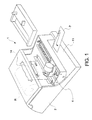
- Fig. 1 is a perspective view showing a multi-functional imaging apparatus with a printing device, which is constructed according to the present invention
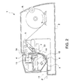
- Fig. 2 is a cross sectional view of the multi-functional imaging apparatus of Fig. 1.
- the multi-functional imaging apparatus reads magnetic ink character recognition (MICR) characters, which are printed on a sheet, such as a personal check, and prints characters such as an endorsement in accordance with the readout result.
- MICR magnetic ink character recognition
- the printing devices and platen mechanisms of the invention are not limited only to the multi-functional imaging apparatus, but are also applicable to other types of printing machines, such as monofunctional printing machines.
- a multi-functional imaging apparatus 1 includes an information reading unit 3, a first printing unit 4 and a second printing unit 30, and those units are located within a housing 2.
- a sheet transport path (first transport path) 10 for continuously guiding a check sheet P extends from the front side of the multi-functional imaging apparatus 1 to the interior of the apparatus, and is curved upward within the apparatus 1.
- the information reading unit 3, the first printing unit 4, and the second printing unit 30 are disposed along the sheet transport path 10.
- the information reading unit 3 includes a magnetic head for reading information in the form of MICR characters that are printed on a surface of the check sheet P.
- the information may be, but is not limited to, codes indicative of the check validity, and the identification number and the validity time of the check.
- the first printing unit 4 prints on the first side of the check sheet P and the second printing unit 30 prints on the reverse side of the check sheet P.
- the readout result is normally sent to a host machine, such as a POS terminal or an electric cash register (ECR), to which the multi-functional imaging apparatus 1 is coupled.
- the host machine judges if the check is valid, and returns the validity check result to the imaging apparatus.
- the imaging apparatus 1 operates the related printing unit or units for printing in accordance with the validity check result returned from the host.
- the first printing unit 4 has another function to print on a roll paper R, set at a rear portion within the housing 2.
- the roll paper R is guided by a second transport path 5 and led to the first transport path 10 and to the first printing unit 4.
- a first sheet-edge sensor 6 located upstream of a pair of roller 12 (first roller pair).
- the sensor 6 outputs a signal which will be used to drive the first roller pair 12.
- the check sheet P is transported at high speed by the first roller pair 12.
- the information reading unit 3 reads the information of the MICR characters from the moving check sheet P.
- a second sheet-edge sensor 7 senses the check sheet P when it reaches the second printing unit 30, and produces an output signal to the second printing unit 30.
- the second printing unit 30 prints on the reverse side of the check sheet P in accordance with the print data received from the host.
- the check sheet P is fed to the first printing unit 4 by means of a pair of rollers 13 (second roller pair).
- the first printing unit 4 prints on the obverse side of the check sheet P in accordance with the print data received from the host.
- the printed check sheet P is discharged out of the housing 2, through an exit 14.
- Fig. 3 is an enlarged, perspective view schematically showing a key portion of the second printing unit 30.
- the second printing unit 30 includes a print head 31, which is movable in the widthwise directions of the check sheet P.
- the serial type print head is illustrated.
- a shuttle print head is used, such as that disclosed in US-A-4,373,438.
- the shuttle print head simultaneously forms dots on and along a line on a platen 32, the line extending in parallel with the lengthwise direction of the platen.
- An ink ribbon of the detachable cartridge type (not shown) is disposed on the print head 31 to provide an ink ribbon without any slack in front of the print head 31.
- a mask plate 38 shown in Fig. 4 but not shown in this figure for pressing the check sheet P against the platen 32 is also used.
- the platen 32 is confronted with the print head 31.
- the platen consists substantially of a long, cylindrical member extended in the widthwise direction of the check sheet P.
- a shaft 32a passes through the platen 32 such that it is projected outward from both ends of the platen.
- Bearing members 33 are attached to both ends of the shaft 32a.
- the shaft 32a is supported at both ends by a frame 34 with the aid of the bearing members 33.
- the platen 32 is rotatably supported in front of the print head 31.
- the shaft 32a is parallel to guide walls 10a (or two portions of a guide wall 10a) (Fig. 4) defining the first transport path 10 and is also parallel to the moving directions of the print head 31.
- the moving direction of the print head 31 is coincident with the direction in which a pin array thereof forming a dot array is arranged.
- a gear 35 is firmly attached to one end (the right end in Fig. 3) of the shaft 32a.
- the gear is mechanically coupled to a drive source (not shown) via gear trains (Fig. 11).
- the gear receives a drive force from the drive source and transmits it to the platen 32, which in turn rotates.
- the platen 32 has specially designed surfaces arranged in the longitudinal direction. Those surfaces are a support surface 36 and a guide surface 37 in the embodiment under discussion. With rotation of the platen 32, either the support surface 36 or the guide surface 37 faces the print head 31.
- the platen 32 has two stop positions. The positions are when either of the surfaces 36 and 37 is confronted with the print head 31.
- a rotation angle detector 40 is provided for detecting an angular state of the platen 32.
- the rotation angle detector 40 consists of the combination of a rotary encoder 40a and a photo-interrupter 40b.
- the support surface 36 and the guide surface 37 are angularly spaced from each other by an angle of about 180 degrees.
- the platen 32 is positioned such that the support surface 36 looks toward this side, and the guide surface 37 looks toward the rear side and hence it is not illustrated.
- FIG. 4 sectional configuration of the platen 32, its position relative to the print head 31, and the first transport path 10 is illustrated.
- the print head 31 and the platen 32 are opposed to each other, and the guide walls 10a vertically extend above and below the platen 32.
- the guide wall 10a guides the check sheet P being transported.
- the support surface 36 and the guide surface 37 which are formed on the outer peripheral surface of the platen 32, are opposed to each other with respect to the axis of the platen.
- An ink ribbon 41 is located between the print head 31 and the check sheet P.
- An elastic member 38 such as a mask plate is provided. The elastic member brings the check sheet P into close contact with the support surface 36 of the platen 32 in order to keep the distance between the print head 31 and the check sheet P proper.
- the elastic member 38 is mounted on the guide wall 10b which is located close to the print head and forms the first transport path 10. When the check sheet P is absent, the elastic member 38 is in contact with the support surface 36 of the platen 32 to completely close the first transport path 10.
- the elastic member 38 may be formed with a plate spring. It may be extended in parallel with the platen 32, and preferably arranged so as to move together with the print head 31.
- a distance L1 between the center of rotation of the platen 32 and the support surface 36 of the platen 32 is selected so as to provide a proper gap (for example, 0.6mm to 0.9mm) between the support surface 36 and a tip of the print head 31.
- the support surface 36 is substantially flat, however, it may take any other suitable shape.
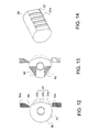
- the support surface 36 may be curved as a part of the cylindrical surface with its center coincident with the shaft 32a of the platen 32 as shown in Fig. 12. In this case, if an angular position of the platen 32 is different from a preset one, the distance of the support surface 36 to the print head is always constant.
- an introducing surface 39 is preferably provided continuous to the support surface 36, as shown in Fig. 4.
- the check sheet P smoothly passes through the printing region even pushing the elastic member 38 away from the support surface 36 to create a gap therebetween if the guide surface 37 of the platen 32 is not confronted with the print head 31, in case where a variation of the transporting speed of the check sheet P offers no problem when the check sheet P is transported to the printing region, for example, for the printing purpose.
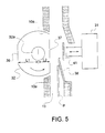
- Fig. 5 shows a state of the platen mechanism when the guide surface 37 of the platen 32 confronts the print head 31, in the sheet transporting mode.
- the platen 32 is retracted from the transportation path 10, the space in front of the print head 31 is enlarged, and the platen 32 is detached from the elastic member 38. In this state, a smooth transportation of the check sheet P is ensured. Namely, when the check sheet P passes through the printing region, one side of the check sheet P facing the platen, is smoothly guided by the guide surface 37 of the platen 32, while the other side of the check sheet P facing the print head, is smoothly guided by the elastic member 38. Therefore, there is no chance that the check sheet P hits the platen 32, the print head 31 or the ink ribbon 41, which might cause its transporting speed to vary. A specific example of the platen mechanism is given below.
- the platen 32 is made of a metal and is 11 mm in diameter, 5mm in L1 and 3mm in L2, the gap G between the tip of the print head 31 and the platen in the print mode is 0.8mm, a distance between the center of rotation of the platen 32 and the front end of the print head 31 is 5.8mm, and the width D of the first transport path 10 is preferably within 2.5 to 3.0mm.
- a plural number of ridges 37d (Fig. 14), extending in the sheet transporting direction, may be formed on the surface of each guide wall 10a to prevent the check sheet P from sticking to the guide wall 10a by an electrostatic force.
- the ends of the guide walls 10a are located in close proximity to the outer peripheral surface of the platen 32. Those ends match the outer peripheral surface of the platen. In this case, at least the ends of the guide surface 37 of the platen 32 needs to match the ends of the guide walls 10a, and the entire outer peripheral surface of the platen does not need to match the ends of the guide walls 10a.
- Fig. 13 there is shown another example of the platen 32.
- the portions 42 of the outer peripheral surface of the platen, which are located between the support surface 36 and the guide surface 37, are substantially flat, not curved.
- the platen in this configuration has a reduced gyrating mass, so that a quick switch between the support surface 36 and the guide surface 37 is realized.
- the surface 42 is designed to be flat with such an intention that it also serves as an introducing surface 39. When the surface 42 does not need to have the function of the introducing surface, the slanted portions described with hatching may be removed from the platen.
- the guide surface 37 of the platen 32 confronts the print head 31, the gap between each guide wall 10a and the guide surface 37 is reduced to the minimum. As a result, a stable transportation of the check sheet P is ensured.
- this gap is about 0.2mm.
- the outer peripheral surface of the platen 32, except those portions of the support surface 36 and the guide surface 37, are arcuate with respect to the center of rotation of the platen 32. Therefore, the radius of rotation of the platen 32 is maximized in the arcuate portions. Therefore, the gaps may be minimized in those portions. It is essential to minimize the gaps in particular when the check sheet P moves through the printing region, the guide surface 37 and the guide walls 10a (Fig. 5). By so doing, there is less chance that the leading edge of the check sheet P hits the gap or is caught by the gap, causing a variation of sheet transporting speed or a paper jam.
- the guide surface 37 of the platen 32 is designed to have three faces 37a, 37b and 37c, which are in parallel with the shaft 32a of the platen 32.
- the design is made taking an angular position error of the platen 32 into account.
- the flat surface 37a if the stop position of the platen 32 shifts in the counterclockwise direction, there is less chance that the platen turns into the first transport path 10 above the guide wall 10a.
- the flat surface 37c if the stop position of the platen 32 shifts in the clockwise direction, there is less chance that the platen turns into the first transport path 10 above the level of the guide wall 10a.
- Those flat surfaces may be substituted by one curved surface.
- the guide wall 10a located downstream in the transporting direction of the check sheet P is preferably provided with a slanted surface 10c for guiding the check sheet P.
- a platen driver unit 60 drives the platen 32 to turn so as to selectively position ether one of the support surface 36 and the guide surface 37 of the platen 32 confronting the print head 31.
- a control unit 61 receives signals from a first sheet-edge sensor 62 corresponding to the first sheet sensor 6 shown in Fig. 2 attached upstream in the sheet transporting direction in the second printing unit 30, a second sheet-edge sensor 63 corresponding the second sheet sensor 7 shown in Fig. 2 attached downstream, and the rotation angle detector 40, and controls the platen driver unit 60 in accordance with those signals received.
- the control unit 61 When the first sheet-edge sensor 62 detects the check sheet P moving through the first transport path, the control unit 61 reads a signal derived from the rotation angle detector 40. When the support surface 36 of the platen 32 confronts the print head 31, the control unit 61 controls the platen driver unit 60 so that the platen 32 is turned 180 degrees to confront the guide surface 37 with the print head 31. As the result of the control, the platen 32 is retracted from the first transport path to allow the check sheet P to be smoothly advanced through the printing region of the second printing unit 30. When a check sheet P is set at a predetermined location in the printing region of the second printing unit 30, the second sheet-edge sensor 63 senses the check sheet P, and sends a detecting signal to the control unit 61.
- control unit 61 controls the platen driver unit 60 so that it turns the platen 32 a predetermined angle (180 degrees in this embodiment) and the support surface 36 confronts the print head. In this state, the second printing unit 30 (Fig. 2) is ready for printing on the check sheet P.
- a check sheet P is inserted into the first transport path 10.
- the platen 32 is turned to confront the guide surface 37 thereof with the print head 31 (step 701).
- the check sheet P is transported to the second printing unit 30 by means of the first roller pair 12, and set at a print location (step 702).
- the platen 32 is turned 180 degrees, and the support surface 36 confronts the print head 31 (step 703).
- the second printing unit 30 starts to print on the check sheet P (step 704).
- the second printing unit 30 completes its printing on the check sheet P, and the check sheet P is discharged out of the second printing unit 30 by means of the second roller pair 13 (step 705).
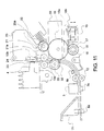
- FIG. 11 a sectional view showing another platen drive mechanism embodying the present invention is illustrated.
- a platen having the same structure as is already described is included in the platen drive mechanism.
- a gear 35 is coupled to the shaft 32a of the platen 32.
- the gear 35 is in mesh with a transmission gear 19 engaging with a clutch gear 18.
- a trigger plunger 15 is provided for coupling or decoupling the clutch gear 18 to or from drive shaft 16.
- a trigger lever 15a When the trigger plunger 15 is placed to an attraction state, a trigger lever 15a is disengaged from a ratchet wheel 17, and the clutch gear 18 is coupled to the drive shaft 16.
- the trigger lever 15a When the trigger plunger 15 is placed to a non-attraction state, the trigger lever 15a is set free to be caused by a compression spring 15b to engage with a pawl 17a, 17b or 17c (Fig. 16) of the ratchet wheel 17, and the clutch gear 18 is decoupled from the drive shaft 16.
- FIG. 15 a perspective view showing the clutch mechanism in the platen drive mechanism is described.
- a clutch spring 26 is closely wound round the drive shaft 16 when no external force acts on it.
- the drive shaft 16 is rotatably and slidably inserted into the clutch gear 18 and the ratchet wheel 17.
- Those component parts of the clutch mechanism are assembled such that one end (first end) 26a of the clutch spring 26 is inserted into a groove 17d of the ratchet wheel 17, and the other end (second end) 26b is inserted into a groove 18a of the clutch gear 18.
- the clutch mechanism will be described. It is assumed that the drive shaft 16 is rotating in the direction of an arrow R.
- the clutch spring 26 receives at its first end 26a a force from the groove 17d of the ratchet wheel 17 (the force has the direction opposite to the direction R, i.e., the direction in which the clutch spring 26 is unwound). Under this condition, the inside diameter of the clutch spring 26 is increased, loses its frictional force to the drive shaft 16, and idly rotates with respect to the drive shaft 16. Accordingly, the clutch gear 18 engaging with the clutch spring 26 also stops, and idly rotates with respect to the drive shaft 16.
- the clutch spring 26 regains its frictional force to the drive shaft 16, and rotates together with the drive shaft 16.
- a load torque of which the direction is opposite to the direction R
- the groove 18a of the clutch gear 18 applies a force to the second end 26b of the clutch spring 26.
- the force further tightens the clutch spring 26 round the drive shaft 16.
- the frictional force between the drive shaft 16 and the clutch spring 26 is increased, and the drive shaft 16 transmits to the clutch gear 18 a drive force which acts to turn the clutch gear 18 while resisting the load.
- the clutch spring 26 slidably moves on and to the drive shaft 16.
- a spring formed by coiling a wire, rectangular in cross section, many turns and side by side, is preferably used for the clutch spring 26.
- the coil is preferably impregnated with lubricant oil.
- a reduction ratio of the clutch gear 18 to the platen 32 is 1.
- the ratchet wheel 17 is provided with the pawls 17a and 17b, which correspond to the position where the support surface 36 of the platen 32 confronts the print head 31, and the position where the guide surface 37 confronts the print head 31. Specifically, when the trigger lever 15a comes in engagement with the pawl 17a, the support surface 36 confronts the print head 31. When it is brought into engagement with the pawl 17b, the guide surface 37 confronts the print head 31.
- the pawl 17c of the ratchet wheel 17 is used to determine an initial position of the platen 32. Reliable engagement of the pawl 17a with the trigger lever 15a is secured by controlling the current feeding time to the trigger plunger 15 in the following procedure. After powered on, the drive shaft is turned by a predetermined quantity of turn to initially engage one of the pawls 17a to 17c with the trigger lever 15a, and current is fed to the trigger plunger 15 for a time period somewhat longer than a time taken for the trigger ratchet wheel to turn half.
- the trigger lever 15a is brought into engagement with the pawl 17c when it has initially engaged with the pawl 17a, and the pawl 17b when it has initially engaged with the pawl 17b or 17c.
- current is fed to the trigger plunger 15 for a time period subtly longer than a time for the ratchet wheel to turn over an angular range from the pawl 17b to the pawl 17c.
- the current feeding time may be a time obtained in advance through measurement. However, the current feeding time is preferably determined in a manner that a quantity of rotation of the drive shaft is detected.
- the proper current feeding time is determined on the basis of the detected rotation quantity. With this current feeding time, it is possible to avoid adverse effects by a variation of load to the drive shaft and a variation of drive voltage.
- the rotation angle detector 40 may be preferably applied for detecting the rotation quantity of the drive shaft.
- the clutch spring 26 When the clutch gear 18 is coupled to or decoupled from the drive shaft 16, the clutch spring 26 is somewhat deformed. Therefore, a rotational phase error is caused between the ratchet wheel 17 and the clutch gear 18 or the platen 32.
- the platen 32 having the guide surface shaped as shown in Fig. 12, is preferably used for the platen drive mechanism incorporating the clutch mechanism thus constructed. Further, the shuttle print head which is insensitive to an angular displacement of the cylinder shaped support surface is preferable in this embodiment.
- the transmission gear 19 is in mesh with a cam gear 21.
- the cam gear 21 includes a cam part 21a located such that a cam follower part 25a of a subframe 25 is brought into contact with the cam part 21a.
- One of the paired rollers 13 is attached to the subframe 25.
- the cam gear 21 when the cam gear 21 is turned, the cam part 21a comes in contact with the cam follower part 25a, the subframe 25 is turned about a fulcrum 24 while resisting a compression coil spring 22, and the roller 13b of the roller pair 13 is shifted to the right in the drawing while moving away from the roller 13a of the roller pair.
- a satisfactory sheet path for the check sheet P is secured in a region located downstream of the platen 32 in the sheet transporting direction.
- the number of teeth of the gear 35 is equal to that of the cam gear 21.
- the platen 32 and the cam part 21a of the cam gear 21 are turned in phase.
- the roller 13b of the roller pair 13 is positioned most apart from the roller 13b when the guide surface 37 of the platen 32 confronts the print head 31.
- a platen 23 of the first printing unit 4 is positioned most apart from the first printing unit 4, to secure a sheet transport path large enough to pass the sheet P therethrough.
- a magnetic head 3 for reading MICR characters and a presser member 3a for pressing a check sheet P against the information reading unit 3 to reduce read errors are provided in the vicinity of the inlet port 11 for the check sheet P.
- the roller pair 12 is used for transporting the check sheet P for the reading of MICR characters by the magnetic head 3.
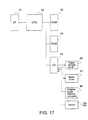
- Fig. 17 shows the hardware scheme in the form of a block diagram.
- An interface 51 physically and logically connects the multi-functional imaging apparatus 1 and a host computer (not shown).
- the interface 51 includes at least a driver for an interface signal, a receiver, and an UART (Universal Asynchronous Receiver Transmitter) circuit for receiving serial data under a predetermined protocol.
- the data fetched, by the interface 51, from the host computer is processed by a central processing unit (CPU) 52 under control of a control program stored in a ROM 53.
- a RAM 54 is used as a storage for temporarily storing data.
- the CPU 52 sends various control signals, via an input/output circuit 55, to such control objects as a driver 56 for the trigger plunger 15, and a driver 57 for driving motors (not shown) as a drive source for the drive shaft 16.
- the CPU also receives through the input/output circuit 55 signals representative of states of various portions in the printing unit, such as an encoder pulse signal representative of a rotation quantity of the drive shaft 16, and a state of the first sheet-edge sensor 6.
- the input/output circuit 55 includes at least a voltage converting circuit for the logic circuit and the drive circuit, and a timing converting circuit, e.g., a latch circuit for the synchronization with the operation of the CPU 52.
- the trigger plunger driver 56 and the driver 57 include at least power transistors and surge absorption diodes.
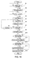
- Fig. 18 is a flow chart showing a method for controlling the platen 32 in the platen drive mechanism.
- a procedure of the control method is stored, in the form of a control program for the CPU 52, in the ROM 53.
- the CPU 52 After powered on, the CPU 52 initializes the platen drive mechanism and analyzes data from the host computer to detect a "MICR read command" (step S1). If the command is detected, the CPU 52 outputs a drive signal of a predetermined length, via the input/output circuit 55, to the trigger plunger driver 56 which in turn confronts the guide surface 37 of the platen 32 with the print head 31 (step S2).
- the predetermined length of the drive signal is obtained by counting the pulses derived from the rotation angle detector 40.
- the first sheet-edge sensor 6 includes a trailing edge sensor 6a and leading edge sensor 6b as shown in Fig. 11 to confirm that the check sheet is properly inserted into the mechanism.
- the controller judges the insertion of the check sheet P when the both sensors 6a and 6b detect presence of an object. If the check sheet P is inserted, the CPU 52 closes the first roller pair 12 located near the inlet port by energizing a plunger solenoid through a drive circuit both not shown.
- the check sheet P is then nipped by the paired rollers 12 for its transportation (step S4).
- the information reading unit 3 reads MICR characters on the check sheet P being transported at high constant speed (step S5). In this case, it is preferable to drive the actuator (not shown) to press the check sheet P against the information reading unit 3 during the reading operation.
- the CPU 52 sends the result of the reading to the host computer, by way of the interface 51 (step S6).
- the host computer analyzes the readout result, and if the re-reading of the MICR characters is required in case of, for example, a decoding error, sends a re-read command to the multi-functional imaging apparatus 1.
- the CPU 52 in the multi-functional imaging apparatus 1 feeds the check sheet P backward to the start position with releasing the presser (step S8), and reads the MICR characters again (step S5).
- the CPU 52 After the reading or re-reading operation, if the CPU 52 receives a print command from the host computer, it confronts the support surface 36 of the platen 32 with the print head (step S9), and prepares for the printing of the obverse and the reverse sides of the check sheet P. In accordance with the contents of the command received, the corresponding printing unit is selected (steps S10, S12) and operated for printing (steps S11, S13), and the printed sheet is discharged from the printing unit. After the reverse side printing, the CPU 52 judges if the obverse side printing is required, on the basis of the command from the host.
- the flat surface is used for the support surface 36 of the platen 32. If required, the outer circumferential surface of the cylindrical platen 32 may directly be used for the support surface 36.
- the guide surface 37 of the platen 32 is also flat in the above-mentioned embodiments. It is designed as to be preferably continuous to the first transport path 10 adjoining to the second printing unit 30; when the first transport path is curved, it is desirable to make the guide surface 37be curved to form a continuous paper guide..
- the support surface 36 and the guide surface 37 are angularly spaced 180 degrees from each other in the above-mentioned embodiments. If necessary, those surfaces may be angularly spaced a proper angle.
- the platen 32 is formed with a single solid body.
- a support portion including the support surface, a guide portion including the guide surface, and an introducing portion including the introducing surface are separate members, and those members are combined to form a platen.
- the present invention is applied to the check sheet processing apparatus for processing a check sheet bearing MICR characters printed thereon. It is evident that the invention is applicable to other apparatus, for example, an apparatus for reading information from a recording medium by use of an OCR with the fixed detector and a bar code reader, an apparatus for printing a recording medium with a magnetic tape attached thereonto.
Landscapes
- Handling Of Sheets (AREA)
Applications Claiming Priority (2)
| Application Number | Priority Date | Filing Date | Title |
|---|---|---|---|
| JP2941398 | 1998-02-12 | ||
| JP2941398 | 1998-02-12 |
Publications (3)
| Publication Number | Publication Date |
|---|---|
| EP0936077A2 true EP0936077A2 (de) | 1999-08-18 |
| EP0936077A3 EP0936077A3 (de) | 2000-04-26 |
| EP0936077B1 EP0936077B1 (de) | 2004-12-22 |
Family
ID=12275453
Family Applications (1)
| Application Number | Title | Priority Date | Filing Date |
|---|---|---|---|
| EP99102678A Expired - Lifetime EP0936077B1 (de) | 1998-02-12 | 1999-02-12 | Schreibträgermechanismus, Druckgerät mit diesem Schreibträgermechanismus und Verfahren zur Steuerung des Druckgerätes |
Country Status (3)
| Country | Link |
|---|---|
| US (2) | US6261008B1 (de) |
| EP (1) | EP0936077B1 (de) |
| DE (1) | DE69922718T2 (de) |
Cited By (4)
| Publication number | Priority date | Publication date | Assignee | Title |
|---|---|---|---|---|
| EP1289761A4 (de) * | 2000-05-24 | 2004-07-14 | Silverbrook Res Pty Ltd | Rotierendes plattenelement |
| CN103158375A (zh) * | 2011-12-09 | 2013-06-19 | 冲电气工业株式会社 | 印刷装置 |
| US8696096B2 (en) | 2000-05-23 | 2014-04-15 | Zamtec Ltd | Laminated ink supply structure mounted in ink distribution arrangement of an inkjet printer |
| US8702205B2 (en) | 2000-05-23 | 2014-04-22 | Zamtec Ltd | Printhead assembly incorporating ink distribution assembly |
Families Citing this family (17)
| Publication number | Priority date | Publication date | Assignee | Title |
|---|---|---|---|---|
| US6704553B1 (en) * | 1997-10-08 | 2004-03-09 | Thomas M. Eubanks | System and method for providing automatic tuning of a radio receiver and for providing automatic control of a CD/tape player |
| JP2001205833A (ja) * | 2000-01-27 | 2001-07-31 | Seiko Precision Inc | ドットプリンタ |
| JP3727211B2 (ja) * | 2000-01-28 | 2005-12-14 | 株式会社沖データ | プラテンおよび印字装置 |
| US6857803B2 (en) | 2001-01-08 | 2005-02-22 | Vutek, Inc. | Printing system web guide with a removable platen |
| US6679640B2 (en) | 2001-01-08 | 2004-01-20 | Vutek, Incorporated | Printing system web guide coupling assembly |
| CA2381375A1 (en) * | 2002-04-10 | 2003-10-10 | Rdm Corporation | Document processing machine |
| SG122813A1 (en) * | 2003-01-24 | 2006-06-29 | Seiko Epson Corp | Printing apparatus and printing method |
| US7665655B2 (en) * | 2003-04-10 | 2010-02-23 | Rdm Corporation | Apparatus and method for presenting both faces of a document for processing |
| US8255417B2 (en) * | 2003-05-20 | 2012-08-28 | Google Inc. | System and method for providing definitions |
| KR100619072B1 (ko) * | 2005-04-04 | 2006-08-31 | 삼성전자주식회사 | 레지스트레이션 장치 및 이를 구비하는 화상형성장치 |
| US8083143B1 (en) * | 2007-08-17 | 2011-12-27 | Burroughs Payment Systems, Inc. | Semi-automatic inertial wheel device in a hand-operated document reader/imager |
| US8359192B2 (en) * | 2008-11-19 | 2013-01-22 | Lemi Technology, Llc | System and method for internet radio station program discovery |
| USD648784S1 (en) * | 2009-07-23 | 2011-11-15 | Provo Craft And Novelty, Inc. | Platen |
| JP2011178144A (ja) * | 2010-03-04 | 2011-09-15 | Seiko Epson Corp | 媒体処理装置のギャップ制御方法および媒体処理装置 |
| JP2012206497A (ja) | 2011-03-15 | 2012-10-25 | Seiko Epson Corp | 複合型印刷装置 |
| US11284786B2 (en) * | 2019-03-07 | 2022-03-29 | ZSquare Ltd. | Spatial encoding system decoding system imaging system and methods thereof |
| WO2022015314A1 (en) * | 2020-07-16 | 2022-01-20 | Hewlett-Packard Development Company, L.P. | Print apparatus |
Citations (2)
| Publication number | Priority date | Publication date | Assignee | Title |
|---|---|---|---|---|
| US4373438A (en) | 1979-12-28 | 1983-02-15 | Shinshu Seiki Kabushiki Kaisha | Dot printer |
| JPH0811365A (ja) | 1994-07-04 | 1996-01-16 | Oki Electric Ind Co Ltd | ヘッドギャップ調整機構 |
Family Cites Families (14)
| Publication number | Priority date | Publication date | Assignee | Title |
|---|---|---|---|---|
| US4556333A (en) * | 1981-02-02 | 1985-12-03 | Bell & Howell Company | Information printing methods and apparatus |
| JPS62286773A (ja) * | 1986-06-06 | 1987-12-12 | Hitachi Ltd | 熱プリンタのプラテン機構 |
| US4842110A (en) * | 1986-12-08 | 1989-06-27 | Ncr Corporation | Document transport and printing apparatus and associated clutch |
| JPS6458576A (en) | 1987-08-31 | 1989-03-06 | Toshiba Corp | Printer device |
| JPH01226364A (ja) | 1988-03-08 | 1989-09-11 | Nec Data Terminal Ltd | 印字装置 |
| KR920010635B1 (ko) * | 1988-06-03 | 1992-12-12 | 스펙트라, 인코포레이티드 | 열용융 잉크젯트 인쇄시스템 |
| ES2048024B1 (es) * | 1990-04-25 | 1995-02-16 | Fujitsu Ltd | Aparato de impresion provisto de dispositivo de ajuste del intervalo de la cabeza. |
| JPH05124274A (ja) | 1991-11-05 | 1993-05-21 | Seiko Epson Corp | プリンタ |
| GB9226781D0 (en) | 1992-12-23 | 1993-02-17 | Neopost Ltd | Thermal printing apparatus |
| JP2791350B2 (ja) * | 1994-01-28 | 1998-08-27 | セイコープレシジョン株式会社 | 印字装置 |
| US5613783A (en) * | 1995-03-27 | 1997-03-25 | International Business Machines Corporation | Point of sale printer with magnetic reader |
| JPH09286148A (ja) * | 1996-04-24 | 1997-11-04 | Tec Corp | プリンタ |
| US5865547A (en) * | 1997-01-10 | 1999-02-02 | International Business Machines Corporation | Check flipper for point of sale printer and method therefor |
| US5997192A (en) * | 1998-08-07 | 1999-12-07 | Axiohm Transaction Solutions, Inc. | Thermal transfer MICR point-of-sale printer with bi-directional clutch |
-
1999
- 1999-02-12 DE DE69922718T patent/DE69922718T2/de not_active Expired - Lifetime
- 1999-02-12 US US09/249,397 patent/US6261008B1/en not_active Expired - Lifetime
- 1999-02-12 EP EP99102678A patent/EP0936077B1/de not_active Expired - Lifetime
-
2001
- 2001-05-03 US US09/847,366 patent/US6530704B2/en not_active Expired - Lifetime
Patent Citations (2)
| Publication number | Priority date | Publication date | Assignee | Title |
|---|---|---|---|---|
| US4373438A (en) | 1979-12-28 | 1983-02-15 | Shinshu Seiki Kabushiki Kaisha | Dot printer |
| JPH0811365A (ja) | 1994-07-04 | 1996-01-16 | Oki Electric Ind Co Ltd | ヘッドギャップ調整機構 |
Cited By (9)
| Publication number | Priority date | Publication date | Assignee | Title |
|---|---|---|---|---|
| US8696096B2 (en) | 2000-05-23 | 2014-04-15 | Zamtec Ltd | Laminated ink supply structure mounted in ink distribution arrangement of an inkjet printer |
| US8702205B2 (en) | 2000-05-23 | 2014-04-22 | Zamtec Ltd | Printhead assembly incorporating ink distribution assembly |
| EP1289761A4 (de) * | 2000-05-24 | 2004-07-14 | Silverbrook Res Pty Ltd | Rotierendes plattenelement |
| US6966625B2 (en) | 2000-05-24 | 2005-11-22 | Silverbrook Research Pty Ltd | Printing mechanism with a rotating platen assembly |
| US7258430B2 (en) | 2000-05-24 | 2007-08-21 | Silverbrook Research Pty Ltd | Inkjet printing mechanism with a displaceable platen assembly |
| US7758181B2 (en) | 2000-05-24 | 2010-07-20 | Silverbrook Research Pty Ltd | Print engine assembly with twin bearing moldings received within a chassis |
| US8678550B2 (en) | 2000-05-24 | 2014-03-25 | Zamtec Ltd | Printhead assembly with laminated ink distribution stack |
| CN103158375A (zh) * | 2011-12-09 | 2013-06-19 | 冲电气工业株式会社 | 印刷装置 |
| CN103158375B (zh) * | 2011-12-09 | 2016-07-27 | 冲电气工业株式会社 | 印刷装置 |
Also Published As
| Publication number | Publication date |
|---|---|
| US6530704B2 (en) | 2003-03-11 |
| US6261008B1 (en) | 2001-07-17 |
| DE69922718T2 (de) | 2005-12-15 |
| US20010016137A1 (en) | 2001-08-23 |
| EP0936077A3 (de) | 2000-04-26 |
| EP0936077B1 (de) | 2004-12-22 |
| DE69922718D1 (de) | 2005-01-27 |
Similar Documents
| Publication | Publication Date | Title |
|---|---|---|
| EP0936077B1 (de) | Schreibträgermechanismus, Druckgerät mit diesem Schreibträgermechanismus und Verfahren zur Steuerung des Druckgerätes | |
| EP0609560B1 (de) | Bogenförderapparat | |
| US8953867B2 (en) | Recording device and control method for a recording device | |
| EP0895868B1 (de) | Vorrichtung zur Verarbeitung eines mit Information bestückten Aufzeichnungsträgers | |
| CA2344131C (en) | Print-medium transport unit | |
| US7520584B2 (en) | Recording apparatus, and feed control method of recording medium in the apparatus | |
| US8092004B2 (en) | Image recording apparatus | |
| EP1468835A1 (de) | Drucker | |
| KR100311293B1 (ko) | 프린터 | |
| US6259808B1 (en) | Thermal transfer MICR printer | |
| US6832723B2 (en) | Scanner apparatus and multifunction device having a scanner | |
| US5997192A (en) | Thermal transfer MICR point-of-sale printer with bi-directional clutch | |
| JP3871008B2 (ja) | プラテン機構、それを用いた印刷装置及びその制御方法 | |
| US6183148B1 (en) | Thermal transfer MICR printer | |
| JP4314174B2 (ja) | 記録装置及び該装置における記録媒体の搬送制御方法 | |
| JPS6325953B2 (de) | ||
| JP3491945B2 (ja) | 自動改頁機構 | |
| EP1068957B1 (de) | Drucker und Steuerungsverfahren dafür | |
| JP4411998B2 (ja) | 重送検出装置、複合処理装置及び重送検出方法 | |
| JP3531303B2 (ja) | プリンタおよびその制御方法 | |
| JP2005225581A (ja) | 重送検出装置、複合処理装置及び重送検出方法 | |
| JP4145626B2 (ja) | スキャナ装置の搬送ローラ機構及びこれを用いたスキャナ装置 | |
| JP2002361957A (ja) | 磁気読取装置搭載プリンタ及びチェック紙の印字方法 | |
| JPH035169A (ja) | プリンタ | |
| JP2021190821A (ja) | 印刷装置、及び印刷装置の制御方法 |
Legal Events
| Date | Code | Title | Description |
|---|---|---|---|
| PUAI | Public reference made under article 153(3) epc to a published international application that has entered the european phase |
Free format text: ORIGINAL CODE: 0009012 |
|
| AK | Designated contracting states |
Kind code of ref document: A2 Designated state(s): DE FR GB IT |
|
| AX | Request for extension of the european patent |
Free format text: AL;LT;LV;MK;RO;SI |
|
| PUAL | Search report despatched |
Free format text: ORIGINAL CODE: 0009013 |
|
| AK | Designated contracting states |
Kind code of ref document: A3 Designated state(s): AT BE CH CY DE DK ES FI FR GB GR IE IT LI LU MC NL PT SE |
|
| AX | Request for extension of the european patent |
Free format text: AL;LT;LV;MK;RO;SI |
|
| 17P | Request for examination filed |
Effective date: 20000809 |
|
| AKX | Designation fees paid |
Free format text: DE FR GB IT |
|
| 17Q | First examination report despatched |
Effective date: 20040121 |
|
| GRAP | Despatch of communication of intention to grant a patent |
Free format text: ORIGINAL CODE: EPIDOSNIGR1 |
|
| GRAS | Grant fee paid |
Free format text: ORIGINAL CODE: EPIDOSNIGR3 |
|
| GRAA | (expected) grant |
Free format text: ORIGINAL CODE: 0009210 |
|
| AK | Designated contracting states |
Kind code of ref document: B1 Designated state(s): DE FR GB IT |
|
| REG | Reference to a national code |
Ref country code: GB Ref legal event code: FG4D |
|
| REF | Corresponds to: |
Ref document number: 69922718 Country of ref document: DE Date of ref document: 20050127 Kind code of ref document: P |
|
| PLBE | No opposition filed within time limit |
Free format text: ORIGINAL CODE: 0009261 |
|
| STAA | Information on the status of an ep patent application or granted ep patent |
Free format text: STATUS: NO OPPOSITION FILED WITHIN TIME LIMIT |
|
| 26N | No opposition filed |
Effective date: 20050923 |
|
| ET | Fr: translation filed | ||
| PGFP | Annual fee paid to national office [announced via postgrant information from national office to epo] |
Ref country code: FR Payment date: 20140211 Year of fee payment: 16 Ref country code: IT Payment date: 20140211 Year of fee payment: 16 |
|
| PGFP | Annual fee paid to national office [announced via postgrant information from national office to epo] |
Ref country code: GB Payment date: 20140212 Year of fee payment: 16 |
|
| PGFP | Annual fee paid to national office [announced via postgrant information from national office to epo] |
Ref country code: DE Payment date: 20140417 Year of fee payment: 16 |
|
| REG | Reference to a national code |
Ref country code: DE Ref legal event code: R119 Ref document number: 69922718 Country of ref document: DE |
|
| GBPC | Gb: european patent ceased through non-payment of renewal fee |
Effective date: 20150212 |
|
| REG | Reference to a national code |
Ref country code: FR Ref legal event code: ST Effective date: 20151030 |
|
| PG25 | Lapsed in a contracting state [announced via postgrant information from national office to epo] |
Ref country code: IT Free format text: LAPSE BECAUSE OF NON-PAYMENT OF DUE FEES Effective date: 20150212 |
|
| PG25 | Lapsed in a contracting state [announced via postgrant information from national office to epo] |
Ref country code: DE Free format text: LAPSE BECAUSE OF NON-PAYMENT OF DUE FEES Effective date: 20150901 Ref country code: GB Free format text: LAPSE BECAUSE OF NON-PAYMENT OF DUE FEES Effective date: 20150212 |
|
| PG25 | Lapsed in a contracting state [announced via postgrant information from national office to epo] |
Ref country code: FR Free format text: LAPSE BECAUSE OF NON-PAYMENT OF DUE FEES Effective date: 20150302 |