US8678550B2 - Printhead assembly with laminated ink distribution stack - Google Patents
Printhead assembly with laminated ink distribution stack Download PDFInfo
- Publication number
- US8678550B2 US8678550B2 US12/834,893 US83489310A US8678550B2 US 8678550 B2 US8678550 B2 US 8678550B2 US 83489310 A US83489310 A US 83489310A US 8678550 B2 US8678550 B2 US 8678550B2
- Authority
- US
- United States
- Prior art keywords
- ink
- pct
- printhead
- assembly
- Prior art date
- Legal status (The legal status is an assumption and is not a legal conclusion. Google has not performed a legal analysis and makes no representation as to the accuracy of the status listed.)
- Expired - Fee Related, expires
Links
Images


Classifications
-
- B—PERFORMING OPERATIONS; TRANSPORTING
- B41—PRINTING; LINING MACHINES; TYPEWRITERS; STAMPS
- B41J—TYPEWRITERS; SELECTIVE PRINTING MECHANISMS, i.e. MECHANISMS PRINTING OTHERWISE THAN FROM A FORME; CORRECTION OF TYPOGRAPHICAL ERRORS
- B41J2/00—Typewriters or selective printing mechanisms characterised by the printing or marking process for which they are designed
- B41J2/005—Typewriters or selective printing mechanisms characterised by the printing or marking process for which they are designed characterised by bringing liquid or particles selectively into contact with a printing material
- B41J2/01—Ink jet
- B41J2/17—Ink jet characterised by ink handling
- B41J2/175—Ink supply systems ; Circuit parts therefor
- B41J2/17503—Ink cartridges
- B41J2/1752—Mounting within the printer
- B41J2/17523—Ink connection
-
- B—PERFORMING OPERATIONS; TRANSPORTING
- B41—PRINTING; LINING MACHINES; TYPEWRITERS; STAMPS
- B41J—TYPEWRITERS; SELECTIVE PRINTING MECHANISMS, i.e. MECHANISMS PRINTING OTHERWISE THAN FROM A FORME; CORRECTION OF TYPOGRAPHICAL ERRORS
- B41J11/00—Devices or arrangements of selective printing mechanisms, e.g. ink-jet printers or thermal printers, for supporting or handling copy material in sheet or web form
- B41J11/02—Platens
- B41J11/04—Roller platens
- B41J11/057—Structure of the surface
-
- B—PERFORMING OPERATIONS; TRANSPORTING
- B41—PRINTING; LINING MACHINES; TYPEWRITERS; STAMPS
- B41J—TYPEWRITERS; SELECTIVE PRINTING MECHANISMS, i.e. MECHANISMS PRINTING OTHERWISE THAN FROM A FORME; CORRECTION OF TYPOGRAPHICAL ERRORS
- B41J11/00—Devices or arrangements of selective printing mechanisms, e.g. ink-jet printers or thermal printers, for supporting or handling copy material in sheet or web form
- B41J11/02—Platens
- B41J11/06—Flat page-size platens or smaller flat platens having a greater size than line-size platens
-
- B—PERFORMING OPERATIONS; TRANSPORTING
- B41—PRINTING; LINING MACHINES; TYPEWRITERS; STAMPS
- B41J—TYPEWRITERS; SELECTIVE PRINTING MECHANISMS, i.e. MECHANISMS PRINTING OTHERWISE THAN FROM A FORME; CORRECTION OF TYPOGRAPHICAL ERRORS
- B41J11/00—Devices or arrangements of selective printing mechanisms, e.g. ink-jet printers or thermal printers, for supporting or handling copy material in sheet or web form
- B41J11/02—Platens
- B41J11/08—Bar or like line-size platens
-
- B—PERFORMING OPERATIONS; TRANSPORTING
- B41—PRINTING; LINING MACHINES; TYPEWRITERS; STAMPS
- B41J—TYPEWRITERS; SELECTIVE PRINTING MECHANISMS, i.e. MECHANISMS PRINTING OTHERWISE THAN FROM A FORME; CORRECTION OF TYPOGRAPHICAL ERRORS
- B41J11/00—Devices or arrangements of selective printing mechanisms, e.g. ink-jet printers or thermal printers, for supporting or handling copy material in sheet or web form
- B41J11/02—Platens
- B41J11/14—Platen-shift mechanisms; Driving gear therefor
-
- B—PERFORMING OPERATIONS; TRANSPORTING
- B41—PRINTING; LINING MACHINES; TYPEWRITERS; STAMPS
- B41J—TYPEWRITERS; SELECTIVE PRINTING MECHANISMS, i.e. MECHANISMS PRINTING OTHERWISE THAN FROM A FORME; CORRECTION OF TYPOGRAPHICAL ERRORS
- B41J11/00—Devices or arrangements of selective printing mechanisms, e.g. ink-jet printers or thermal printers, for supporting or handling copy material in sheet or web form
- B41J11/20—Platen adjustments for varying the strength of impression, for a varying number of papers, for wear or for alignment, or for print gap adjustment
-
- B—PERFORMING OPERATIONS; TRANSPORTING
- B41—PRINTING; LINING MACHINES; TYPEWRITERS; STAMPS
- B41J—TYPEWRITERS; SELECTIVE PRINTING MECHANISMS, i.e. MECHANISMS PRINTING OTHERWISE THAN FROM A FORME; CORRECTION OF TYPOGRAPHICAL ERRORS
- B41J2/00—Typewriters or selective printing mechanisms characterised by the printing or marking process for which they are designed
- B41J2/005—Typewriters or selective printing mechanisms characterised by the printing or marking process for which they are designed characterised by bringing liquid or particles selectively into contact with a printing material
- B41J2/01—Ink jet
- B41J2/135—Nozzles
- B41J2/145—Arrangement thereof
- B41J2/155—Arrangement thereof for line printing
-
- B—PERFORMING OPERATIONS; TRANSPORTING
- B41—PRINTING; LINING MACHINES; TYPEWRITERS; STAMPS
- B41J—TYPEWRITERS; SELECTIVE PRINTING MECHANISMS, i.e. MECHANISMS PRINTING OTHERWISE THAN FROM A FORME; CORRECTION OF TYPOGRAPHICAL ERRORS
- B41J2/00—Typewriters or selective printing mechanisms characterised by the printing or marking process for which they are designed
- B41J2/005—Typewriters or selective printing mechanisms characterised by the printing or marking process for which they are designed characterised by bringing liquid or particles selectively into contact with a printing material
- B41J2/01—Ink jet
- B41J2/135—Nozzles
- B41J2/165—Prevention or detection of nozzle clogging, e.g. cleaning, capping or moistening for nozzles
- B41J2/16505—Caps, spittoons or covers for cleaning or preventing drying out
- B41J2/16508—Caps, spittoons or covers for cleaning or preventing drying out connected with the printer frame
-
- B—PERFORMING OPERATIONS; TRANSPORTING
- B41—PRINTING; LINING MACHINES; TYPEWRITERS; STAMPS
- B41J—TYPEWRITERS; SELECTIVE PRINTING MECHANISMS, i.e. MECHANISMS PRINTING OTHERWISE THAN FROM A FORME; CORRECTION OF TYPOGRAPHICAL ERRORS
- B41J2/00—Typewriters or selective printing mechanisms characterised by the printing or marking process for which they are designed
- B41J2/005—Typewriters or selective printing mechanisms characterised by the printing or marking process for which they are designed characterised by bringing liquid or particles selectively into contact with a printing material
- B41J2/01—Ink jet
- B41J2/135—Nozzles
- B41J2/165—Prevention or detection of nozzle clogging, e.g. cleaning, capping or moistening for nozzles
- B41J2/16585—Prevention or detection of nozzle clogging, e.g. cleaning, capping or moistening for nozzles for paper-width or non-reciprocating print heads
-
- B—PERFORMING OPERATIONS; TRANSPORTING
- B41—PRINTING; LINING MACHINES; TYPEWRITERS; STAMPS
- B41J—TYPEWRITERS; SELECTIVE PRINTING MECHANISMS, i.e. MECHANISMS PRINTING OTHERWISE THAN FROM A FORME; CORRECTION OF TYPOGRAPHICAL ERRORS
- B41J2/00—Typewriters or selective printing mechanisms characterised by the printing or marking process for which they are designed
- B41J2/005—Typewriters or selective printing mechanisms characterised by the printing or marking process for which they are designed characterised by bringing liquid or particles selectively into contact with a printing material
- B41J2/01—Ink jet
- B41J2/17—Ink jet characterised by ink handling
- B41J2/175—Ink supply systems ; Circuit parts therefor
-
- B—PERFORMING OPERATIONS; TRANSPORTING
- B41—PRINTING; LINING MACHINES; TYPEWRITERS; STAMPS
- B41J—TYPEWRITERS; SELECTIVE PRINTING MECHANISMS, i.e. MECHANISMS PRINTING OTHERWISE THAN FROM A FORME; CORRECTION OF TYPOGRAPHICAL ERRORS
- B41J2/00—Typewriters or selective printing mechanisms characterised by the printing or marking process for which they are designed
- B41J2/005—Typewriters or selective printing mechanisms characterised by the printing or marking process for which they are designed characterised by bringing liquid or particles selectively into contact with a printing material
- B41J2/01—Ink jet
- B41J2/17—Ink jet characterised by ink handling
- B41J2/18—Ink recirculation systems
- B41J2/185—Ink-collectors; Ink-catchers
-
- B—PERFORMING OPERATIONS; TRANSPORTING
- B41—PRINTING; LINING MACHINES; TYPEWRITERS; STAMPS
- B41J—TYPEWRITERS; SELECTIVE PRINTING MECHANISMS, i.e. MECHANISMS PRINTING OTHERWISE THAN FROM A FORME; CORRECTION OF TYPOGRAPHICAL ERRORS
- B41J29/00—Details of, or accessories for, typewriters or selective printing mechanisms not otherwise provided for
- B41J29/02—Framework
-
- B—PERFORMING OPERATIONS; TRANSPORTING
- B41—PRINTING; LINING MACHINES; TYPEWRITERS; STAMPS
- B41J—TYPEWRITERS; SELECTIVE PRINTING MECHANISMS, i.e. MECHANISMS PRINTING OTHERWISE THAN FROM A FORME; CORRECTION OF TYPOGRAPHICAL ERRORS
- B41J29/00—Details of, or accessories for, typewriters or selective printing mechanisms not otherwise provided for
- B41J29/38—Drives, motors, controls or automatic cut-off devices for the entire printing mechanism
-
- B—PERFORMING OPERATIONS; TRANSPORTING
- B41—PRINTING; LINING MACHINES; TYPEWRITERS; STAMPS
- B41J—TYPEWRITERS; SELECTIVE PRINTING MECHANISMS, i.e. MECHANISMS PRINTING OTHERWISE THAN FROM A FORME; CORRECTION OF TYPOGRAPHICAL ERRORS
- B41J2/00—Typewriters or selective printing mechanisms characterised by the printing or marking process for which they are designed
- B41J2/005—Typewriters or selective printing mechanisms characterised by the printing or marking process for which they are designed characterised by bringing liquid or particles selectively into contact with a printing material
- B41J2/01—Ink jet
- B41J2/135—Nozzles
- B41J2/14—Structure thereof only for on-demand ink jet heads
- B41J2002/14362—Assembling elements of heads
Definitions
- the following invention relates to a rotating platen member for a printer. More particularly, though not exclusively, the invention relates to a rotating platen member incorporating a platen surface, a capping device and a test print blotter for an A4 pagewidth drop on demand printhead in a printer.
- the overall design of a printer in which the rotating platen member can be utilized revolves around the use of replaceable printhead modules in an array approximately 8 inches (20 cm) long.
- An advantage of such a system is the ability to easily remove and replace any defective modules in a printhead array. This would eliminate having to scrap an entire printhead if only one chip is defective.
- a printhead module in such a printer can be comprised of a “Memjet” chip, being a chip having mounted thereon a vast number of thermo-actuators in micro-mechanics and micro-electromechanical systems (MEMS).
- MEMS micro-electromechanical systems
- Such actuators might be those as disclosed in U.S. Pat. No. 6,044,646 to the present applicant, however, there might be other MEMS print chips.
- the printhead being the environment within which the rotating platen member of the present invention is to be situated, might typically have six ink chambers and be capable of printing four color process (CMYK) as well as infra-red ink and fixative.
- An air pump would supply filtered air to the printhead, which could be used to keep foreign particles away from its ink nozzles.
- the printhead module is typically to be connected to a replaceable cassette which contains the ink supply and an air filter.
- Each printhead module receives ink via a distribution molding that transfers the ink.
- a distribution molding that transfers the ink.
- ten modules butt together to form a complete eight inch printhead assembly suitable for printing A4 paper without the need for scanning movement of the printhead across the paper width.
- the printheads themselves are modular, so complete eight inch printhead arrays can be configured to form printheads of arbitrary width.
- a second printhead assembly can be mounted on the opposite side of a paper feed path to enable double-sided high speed printing.
- a print engine assembly includes an elongate chassis defining a print media exit slot; an elongate printhead assembly mounted relative to the chassis and configured to eject ink onto print media; a paper feed mechanism configured to transport the print media past the elongate printhead and out through the exit slot, the paper feed mechanism comprising a pair of bearing moldings received within and mounted on opposite ends of the chassis, the paper feed mechanism further comprising at least one roller mounted between the bearing moldings and a motor mounted to one of said bearing moldings to drive said at least one roller; and a platen member extending parallel to the printhead, the platen member mounted in the bearing moldings.
- a pair of spacers is mounted to either end of the chassis and on which said printhead assembly is mounted.
- FIG. 1 is a front perspective view of a print engine assembly
- FIG. 2 is a rear perspective view of the print engine assembly of FIG. 1
- FIG. 3 is an exploded perspective view of the print engine assembly of FIG. 1 .
- FIG. 4 is a schematic front perspective view of a printhead assembly.
- FIG. 5 is a rear schematic perspective view of the printhead assembly of FIG. 4 .
- FIG. 6 is an exploded perspective illustration of the printhead assembly.
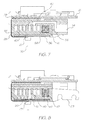
- FIG. 7 is a cross-sectional end elevational view of the printhead assembly of FIGS. 4 to 6 with the section taken through the centre of the printhead.
- FIG. 8 is a schematic cross-sectional end elevational view of the printhead assembly of FIGS. 4 to 6 taken near the left end of FIG. 4 .
- FIG. 9A is a schematic end elevational view of mounting of the print chip and nozzle guard in the laminated stack structure of the printhead
- FIG. 9B is an enlarged end elevational cross section of FIG. 9A
- FIG. 10 is an exploded perspective illustration of a printhead cover assembly.
- FIG. 11 is a schematic perspective illustration of an ink distribution molding.
- FIG. 12 is an exploded perspective illustration showing the layers forming part of a laminated ink distribution structure according to the present invention.
- FIG. 13 is a stepped sectional view from above of the structure depicted in FIGS. 9A and 9B ,
- FIG. 14 is a stepped sectional view from below of the structure depicted in FIG. 13 .
- FIG. 15 is a schematic perspective illustration of a first laminate layer.
- FIG. 16 is a schematic perspective illustration of a second laminate layer.
- FIG. 17 is a schematic perspective illustration of a third laminate layer.
- FIG. 18 is a schematic perspective illustration of a fourth laminate layer.
- FIG. 19 is a schematic perspective illustration of a fifth laminate layer.
- FIG. 20 is a perspective view of the air valve molding
- FIG. 21 is a rear perspective view of the right hand end of the platen
- FIG. 22 is a rear perspective view of the left hand end of the platen
- FIG. 23 is an exploded view of the platen
- FIG. 24 is a transverse cross-sectional view of the platen
- FIG. 25 is a front perspective view of the optical paper sensor arrangement
- FIG. 26 is a schematic perspective illustration of a printhead assembly and ink lines attached to an ink reservoir cassette.
- FIG. 27 is a partly exploded view of FIG. 26 .
- FIGS. 1 to 3 of the accompanying drawings there is schematically depicted the core components of a print engine assembly, showing the general environment in which the laminated ink distribution structure of the present invention can be located.
- the print engine assembly includes a chassis 10 fabricated from pressed steel, aluminium, plastics or other rigid material. Chassis 10 is intended to be mounted within the body of a printer and serves to mount a printhead assembly 11 , a paper feed mechanism and other related components within the external plastics casing of a printer.
- the chassis 10 supports the printhead assembly 11 such that ink is ejected therefrom and onto a sheet of paper or other print medium being transported below the printhead then through exit slot 19 by the feed mechanism.
- the paper feed mechanism includes a feed roller 12 , feed idler rollers 13 , a platen generally designated as 14 , exit rollers 15 and a pin wheel assembly 16 , all driven by a stepper motor 17 .
- These paper feed components are mounted between a pair of bearing moldings 18 , which are in turn mounted to the chassis 10 at each respective end thereof.
- a printhead assembly 11 is mounted to the chassis 10 by means of respective printhead spacers 20 mounted to the chassis 10 .
- the spacer moldings 20 increase the printhead assembly length to 220 mm allowing clearance on either side of 210 mm wide paper.
- the printhead construction is shown generally in FIGS. 4 to 8 .
- the printhead assembly 11 includes a printed circuit board (PCB) 21 having mounted thereon various electronic components including a 64 MB DRAM 22 , a PEC chip 23 , a QA chip connector 24 , a microcontroller 25 , and a dual motor driver chip 26 .
- the printhead is typically 203 mm long and has ten print chips 27 ( FIG. 13 ), each typically 21 mm long. These print chips 27 are each disposed at a slight angle to the longitudinal axis of the printhead (see FIG. 12 ), with a slight overlap between each print chip which enables continuous transmission of ink over the entire length of the array.
- Each print chip 27 is electronically connected to an end of one of the tape automated bond (TAB) films 28 , the other end of which is maintained in electrical contact with the undersurface of the printed circuit board 21 by means of a TAB film backing pad 29 .
- TAB tape automated bond
- Each such print chip 27 is approximately 21 mm long, less than 1 mm wide and about 0.3 mm high, and has on its lower surface thousands of MEMS inkjet nozzles 30 , shown schematically in FIGS. 9A and 9B , arranged generally in six lines—one for each ink type to be applied. Each line of nozzles may follow a staggered pattern to allow closer dot spacing. Six corresponding lines of ink passages 31 extend through from the rear of the print chip to transport ink to the rear of each nozzle. To protect the delicate nozzles on the surface of the print chip each print chip has a nozzle guard 43 , best seen in FIG. 9A , with microapertures 44 aligned with the nozzles 30 , so that the ink drops ejected at high speed from the nozzles pass through these microapertures to be deposited on the paper passing over the platen 14 .
- Ink is delivered to the print chips via a distribution molding 35 and laminated stack 36 arrangement forming part of the printhead 11 .
- Ink from an ink cassette 37 ( FIGS. 26 and 27 ) is relayed via individual ink hoses 38 to individual ink inlet ports 34 integrally molded with a plastics duct cover 39 which forms a lid over the plastics distribution molding 35 .
- the distribution molding 35 includes six individual longitudinal ink ducts 40 and an air duct 41 which extend throughout the length of the array. Ink is transferred from the inlet ports 34 to respective ink ducts 40 via individual cross-flow ink channels 42 , as best seen with reference to FIG. 7 .
- ducts there are six ducts depicted, a different number of ducts might be provided. Six ducts are suitable for a printer capable of printing four color process (CMYK) as well as infra-red ink and fixative.
- CYK color process
- Air is delivered to the air duct 41 via an air inlet port 61 , to supply air to each print chip 27 , as described later with reference to FIGS. 6 to 8 , 20 and 21 .
- the TAB film 28 extends from the undersurface of the printhead PCB 21 , around the rear of the distribution molding 35 to be received within a respective TAB film recess 46 ( FIG. 21 ), a number of which are situated along a chip housing layer 47 of the laminated stack 36 .
- the TAB film relays electrical signals from the printed circuit board 21 to individual print chips 27 supported by the laminated structure.
- the distribution molding, laminated stack 36 and associated components are best described with reference to FIGS. 7 to 19 .
- FIG. 10 depicts the distribution molding cover 39 formed as a plastics molding and including a number of positioning spigots 48 which serve to locate the upper printhead cover 49 thereon.
- an ink transfer port 50 connects one of the ink ducts 39 (the fourth duct from the left) down to one of six lower ink ducts or transitional ducts 51 in the underside of the distribution molding. All of the ink ducts 40 have corresponding transfer ports 50 communicating with respective ones of the transitional ducts 51 .
- the transitional ducts 51 are parallel with each other but angled acutely with respect to the ink ducts 40 so as to line up with the rows of ink holes of the first layer 52 of the laminated stack 36 to be described below.
- the first layer 52 incorporates twenty four individual ink holes 53 for each of ten print chips 27 . That is, where ten such print chips are provided, the first layer 52 includes two hundred and forty ink holes 53 . The first layer 52 also includes a row of air holes 54 alongside one longitudinal edge thereof.
- the individual groups of twenty four ink holes 53 are formed generally in a rectangular array with aligned rows of ink holes. Each row of four ink holes is aligned with a transitional duct 51 and is parallel to a respective print chip.
- the undersurface of the first layer 52 includes underside recesses 55 .
- Each recess 55 communicates with one of the ink holes of the two centre-most rows of four holes 53 (considered in the direction transversely across the layer 52 ). That is, holes 53 a ( FIG. 13 ) deliver ink to the right hand recess 55 a shown in FIG. 14 , whereas the holes 53 b deliver ink to the left most underside recesses 55 b shown in FIG. 14 .
- the second layer 56 includes a pair of slots 57 , each receiving ink from one of the underside recesses 55 of the first layer.
- the second layer 56 also includes ink holes 53 which are aligned with the outer two sets of ink holes 53 of the first layer 52 . That is, ink passing through the outer sixteen ink holes 53 of the first layer 52 for each print chip pass directly through corresponding holes 53 passing through the second layer 56 .
- the underside of the second layer 56 has formed therein a number of transversely extending channels 58 to relay ink passing through ink holes 53 c and 53 d toward the centre. These channels extend to align with a pair of slots 59 formed through a third layer 60 of the laminate.
- the third layer 60 of the laminate includes four slots 59 corresponding with each print chip, with two inner slots being aligned with the pair of slots formed in the second layer 56 and outer slots between which the inner slots reside.
- the third layer 60 also includes an array of air holes 54 aligned with the corresponding air hole arrays 54 provided in the first and second layers 52 and 56 .
- the third layer 60 has only eight remaining ink holes 53 corresponding with each print chip. These outermost holes 53 are aligned with the outermost holes 53 provided in the first and second laminate layers. As shown in FIGS. 9A and 9B , the third layer 60 includes in its underside surface a transversely extending channel 61 corresponding to each hole 53 . These channels 61 deliver ink from the corresponding hole 53 to a position just outside the alignment of slots 59 therethrough.
- the top three layers of the laminated stack 36 thus serve to direct the ink (shown by broken hatched lines in FIG. 9B ) from the more widely spaced ink ducts 40 of the distribution molding to slots aligned with the ink passages 31 through the upper surface of each print chip 27 .
- the slots 57 and 59 can in fact be comprised of discrete co-linear spaced slot segments.
- the fourth layer 62 of the laminated stack 36 includes an array of ten chip-slots 65 each receiving the upper portion of a respective print chip 27 .
- the fifth and final layer 64 also includes an array of chip-slots 65 which receive the chip and nozzle guard assembly 43 .
- the TAB film 28 is sandwiched between the fourth and fifth layers 62 and 64 , one or both of which can be provided with recesses to accommodate the thickness of the TAB film.
- the laminated stack is formed as a precision micro-molding, injection molded in an Acetal type material. It accommodates the array of print chips 27 with the TAB film already attached and mates with the cover molding 39 described earlier.
- Rib details in the underside of the micro-molding provides support for the TAB film when they are bonded together.
- the TAB film forms the underside wall of the printhead module, as there is sufficient structural integrity between the pitch of the ribs to support a flexible film.
- the edges of the TAB film seal on the underside wall of the cover molding 39 .
- the chip is bonded onto one hundred micron wide ribs that run the length of the micro-molding, providing a final ink feed to the print nozzles.
- the design of the micro-molding allow for a physical overlap of the print chips when they are butted in a line. Because the printhead chips now form a continuous strip with a generous tolerance, they can be adjusted digitally to produce a near perfect print pattern rather than relying on very close toleranced moldings and exotic materials to perform the same function.
- the pitch of the modules is typically 20.33 mm.
- the individual layers of the laminated stack as well as the cover molding 39 and distribution molding can be glued or otherwise bonded together to provide a sealed unit.
- the ink paths can be sealed by a bonded transparent plastic film serving to indicate when inks are in the ink paths, so they can be fully capped off when the upper part of the adhesive film is folded over. Ink charging is then complete.
- the four upper layers 52 , 56 , 60 , 62 of the laminated stack 36 have aligned air holes 54 which communicate with air passages 63 formed as channels formed in the bottom surface of the fourth layer 62 , as shown in FIGS. 9 b and 13 .
- These passages provide pressurised air to the space between the print chip surface and the nozzle guard 43 whilst the printer is in operation. Air from this pressurised zone passes through the micro-apertures 44 in the nozzle guard, thus preventing the build-up of any dust or unwanted contaminants at those apertures.
- This supply of pressurised air can be turned off to prevent ink drying on the nozzle surfaces during periods of non-use of the printer, control of this air supply being by means of the air valve assembly shown in FIGS. 6 to 8 , 20 and 21 .
- an air valve molding 66 formed as a channel with a series of apertures 67 in its base.
- the spacing of these apertures corresponds to air passages 68 formed in the base of the air duct 41 (see FIG. 6 ), the air valve molding being movable longitudinally within the air duct so that the apertures 67 can be brought into alignment with passages 68 to allow supply the pressurized air through the laminated stack to the cavity between the print chip and the nozzle guard, or moved out of alignment to close off the air supply.
- Compression springs 69 maintain a sealing inter-engagement of the bottom of the air valve molding 66 with the base of the air duct 41 to prevent leakage when the valve is closed.
- the air valve molding 66 has a cam follower 70 extending from one end thereof, which engages an air valve cam surface 71 on an end cap 74 of the platen 14 so as to selectively move the air valve molding longitudinally within the air duct 41 according to the rotational positional of the multi-function platen 14 , which may be rotated between printing, capping and blotting positions depending on the operational status of the printer, as will be described below in more detail with reference to FIGS. 21 to 24 .
- the cam When the platen 14 is in its rotational position for printing, the cam holds the air valve in its open position to supply air to the print chip surface, whereas when the platen is rotated to the non-printing position in which it caps off the micro-apertures of the nozzle guard, the cam moves the air valve molding to the valve closed position.
- the platen member 14 extends parallel to the printhead, supported by a rotary shaft 73 mounted in bearing molding 18 and rotatable by means of gear 79 (see FIG. 3 ).
- the shaft is provided with a right hand end cap 74 and left hand end cap 75 at respective ends, having cams 76 , 77 .
- the platen member 14 has a platen surface 78 , a capping portion 80 and an exposed blotting portion 81 extending along its length, each separated by 120°.
- the platen member is rotated so that the platen surface 78 is positioned opposite the printhead so that the platen surface acts as a support for that portion of the paper being printed at the time.
- the platen member is rotated so that the capping portion 80 contacts the bottom of the printhead, sealing in a locus surrounding the microapertures 44 .
- This in combination with the closure of the air valve by means of the air valve arrangement when the platen 14 is in its capping position, maintains a closed atmosphere at the print nozzle surface. This serves to reduce evaporation of the ink solvent (usually water) and thus reduce drying of ink on the print nozzles while the printer is not in use.
- the third function of the rotary platen member is as an ink blotter to receive ink from priming of the print nozzles at printer start up or maintenance operations of the printer.
- the platen member 14 is rotated so that the exposed blotting portion 81 is located in the ink ejection path opposite the nozzle guard 43 .
- the exposed blotting portion 81 is an exposed part of a body of blotting material 82 inside the platen member 14 , so that the ink received on the exposed portion 81 is drawn into the body of the platen member.
- the platen member consists generally of an extruded or molded hollow platen body 83 which forms the platen surface 78 and receives the shaped body of blotting material 82 of which a part projects through a longitudinal slot in the platen body to form the exposed blotting surface 81 .
- a flat portion 84 of the platen body 83 serves as a base for attachment of the capping member 80 , which consists of a capper housing 85 , a capper seal member 86 and a foam member 87 for contacting the nozzle guard 43 .
- each bearing molding 18 rides on a pair of vertical rails 101 . That is, the capping assembly is mounted to four vertical rails 101 enabling the assembly to move vertically. A spring 102 under either end of the capping assembly biases the assembly into a raised position, maintaining cams 76 , 77 in contact with the spacer projections 100 .
- the printhead 11 is capped when not is use by the full-width capping member 80 using the elastomeric (or similar) seal 86 .
- the main roller drive motor is reversed. This brings a reversing gear into contact with the gear 79 on the end of the platen assembly and rotates it into one of its three functional positions, each separated by 120°.
- the cams 76 , 77 on the platen end caps 74 , 75 co-operate with projections 100 on the respective printhead spacers 20 to control the spacing between the platen member and the printhead depending on the rotary position of the platen member. In this manner, the platen is moved away from the printhead during the transition between platen positions to provide sufficient clearance from the printhead and moved back to the appropriate distances for its respective paper support, capping and blotting functions.
- the cam arrangement for the rotary platen provides a mechanism for fine adjustment of the distance between the platen surface and the printer nozzles by slight rotation of the platen 14 . This allows compensation of the nozzle-platen distance in response to the thickness of the paper or other material being printed, as detected by the optical paper thickness sensor arrangement illustrated in FIG. 25 .
- the optical paper sensor includes an optical sensor 88 mounted on the lower surface of the PCB 21 and a sensor flag arrangement mounted on the arms 89 protruding from the distribution molding.
- the flag arrangement comprises a sensor flag member 90 mounted on a shaft 91 which is biased by torsion spring 92 . As paper enters the feed rollers, the lowermost portion of the flag member contacts the paper and rotates against the bias of the spring 92 by an amount dependent on the paper thickness.
- the optical sensor detects this movement of the flag member and the PCB responds to the detected paper thickness by causing compensatory rotation of the platen 14 to optimize the distance between the paper surface and the nozzles.
- FIGS. 26 and 27 show attachment of the illustrated printhead assembly to a replaceable ink cassette 93 .
- Six different inks are supplied to the printhead through hoses 94 leading from an array of female ink valves 95 located inside the printer body.
- the replaceable cassette 93 containing a six compartment ink bladder and corresponding male valve array is inserted into the printer and mated to the valves 95 .
- the cassette also contains an air inlet 96 and air filter (not shown), and mates to the air intake connector 97 situated beside the ink valves, leading to the air pump 98 supplying filtered air to the printhead.
- a QA chip is included in the cassette.
- the QA chip meets with a contact 99 located between the ink valves 95 and air intake connector 96 in the printer as the cassette is inserted to provide communication to the QA chip connector 24 on the PCB.
Landscapes
- Ink Jet (AREA)
- Particle Formation And Scattering Control In Inkjet Printers (AREA)
Abstract
Description
-
- PCT/AU00/00518, PCT/AU00/00519, PCT/AU00/00520, PCT/AU00/00521, PCT/AU00/00522, PCT/AU00/00523, PCT/AU00/00524, PCT/AU00/00525, PCT/AU00/00526, PCT/AU00/00527, PCT/AU00/00528, PCT/AU00/00529, PCT/AU00/00530, PCT/AU00/00531, PCT/AU00/00532, PCT/AU00/00533, PCT/AU00/00534, PCT/AU00/00535, PCT/AU00/00536, PCT/AU00/00537, PCT/AU00/00538, PCT/AU00/00539, PCT/AU00/00540, PCT/AU00/00541, PCT/AU00/00542, PCT/AU00/00543, PCT/AU00/00544, PCT/AU00/00545, PCT/AU00/00547, PCT/AU00/00546, PCT/AU00/00554, PCT/AU00/00556, PCT/AU00/00557, PCT/AU00/00558, PCT/AU00/00559, PCT/AU00/00560, PCT/AU00/00561, PCT/AU00/00562, PCT/AU00/00563, PCT/AU00/00564, PCT/AU00/00565, PCT/AU00/00566, PCT/AU00/00567, PCT/AU00/00568, PCT/AU00/00569, PCT/AU00/00570, PCT/AU00/00571, PCT/AU00/00572, PCT/AU00/00573, PCT/AU00/00574, PCT/AU00/00575, PCT/AU00/00576, PCT/AU00/00577, PCT/AU00/00578, PCT/AU00/00579, PCT/AU00/00581, PCT/AU00/00580, PCT/AU00/00582, PCT/AU00/00587, PCT/AU00/00588, PCT/AU00/00589, PCT/AU00/00583, PCT/AU00/00593, PCT/AU00/00590, PCT/AU00/00591, PCT/AU00/00592, PCT/AU00/00584, PCT/AU00/00585, PCT/AU00/00586, PCT/AU00/00594, PCT/AU00/00595, PCT/AU00/00596, PCT/AU00/00597, PCT/AU00/00598, PCT/AU00/00516, PCT/AU00/00517, PCT/AU00/00511, PCT/AU00/00501, PCT/AU00/00502, PCT/AU00/00503, PCT/AU00/00504, PCT/AU00/00505, PCT/AU00/00506, PCT/AU00/00507, PCT/AU00/00508, PCT/AU00/00509, PCT/AU00/00510, PCT/AU00/00512, PCT/AU00/00513, PCT/AU00/00514, PCT/AU00/00515
Claims (4)
Priority Applications (1)
| Application Number | Priority Date | Filing Date | Title |
|---|---|---|---|
| US12/834,893 US8678550B2 (en) | 2000-05-24 | 2010-07-13 | Printhead assembly with laminated ink distribution stack |
Applications Claiming Priority (6)
| Application Number | Priority Date | Filing Date | Title |
|---|---|---|---|
| PCT/AU2000/000597 WO2001089836A1 (en) | 2000-05-24 | 2000-05-24 | Rotating platen member |
| US10/296,438 US6824242B1 (en) | 2000-05-24 | 2000-05-24 | Rotating platen member |
| US10/974,751 US6966625B2 (en) | 2000-05-24 | 2004-10-28 | Printing mechanism with a rotating platen assembly |
| US11/227,240 US7258430B2 (en) | 2000-05-24 | 2005-09-16 | Inkjet printing mechanism with a displaceable platen assembly |
| US11/779,845 US7758181B2 (en) | 2000-05-24 | 2007-07-18 | Print engine assembly with twin bearing moldings received within a chassis |
| US12/834,893 US8678550B2 (en) | 2000-05-24 | 2010-07-13 | Printhead assembly with laminated ink distribution stack |
Related Parent Applications (1)
| Application Number | Title | Priority Date | Filing Date |
|---|---|---|---|
| US11/779,845 Continuation US7758181B2 (en) | 2000-05-24 | 2007-07-18 | Print engine assembly with twin bearing moldings received within a chassis |
Publications (2)
| Publication Number | Publication Date |
|---|---|
| US20100277538A1 US20100277538A1 (en) | 2010-11-04 |
| US8678550B2 true US8678550B2 (en) | 2014-03-25 |
Family
ID=3700816
Family Applications (9)
| Application Number | Title | Priority Date | Filing Date |
|---|---|---|---|
| US10/296,438 Expired - Fee Related US6824242B1 (en) | 2000-05-24 | 2000-05-24 | Rotating platen member |
| US10/974,751 Expired - Fee Related US6966625B2 (en) | 2000-05-24 | 2004-10-28 | Printing mechanism with a rotating platen assembly |
| US11/227,240 Expired - Fee Related US7258430B2 (en) | 2000-05-24 | 2005-09-16 | Inkjet printing mechanism with a displaceable platen assembly |
| US11/779,845 Expired - Fee Related US7758181B2 (en) | 2000-05-24 | 2007-07-18 | Print engine assembly with twin bearing moldings received within a chassis |
| US12/251,450 Abandoned US20090033708A1 (en) | 2000-05-24 | 2008-10-14 | Method of operating an inkjet printer |
| US12/251,448 Abandoned US20090033711A1 (en) | 2000-05-24 | 2008-10-14 | Rotating platen |
| US12/251,447 Abandoned US20090033710A1 (en) | 2000-05-24 | 2008-10-14 | Inkjet printer having an inkjet printhead and a rotating platen |
| US12/251,446 Abandoned US20090033709A1 (en) | 2000-05-24 | 2008-10-14 | Inkjet printing device having rotating platen |
| US12/834,893 Expired - Fee Related US8678550B2 (en) | 2000-05-24 | 2010-07-13 | Printhead assembly with laminated ink distribution stack |
Family Applications Before (8)
| Application Number | Title | Priority Date | Filing Date |
|---|---|---|---|
| US10/296,438 Expired - Fee Related US6824242B1 (en) | 2000-05-24 | 2000-05-24 | Rotating platen member |
| US10/974,751 Expired - Fee Related US6966625B2 (en) | 2000-05-24 | 2004-10-28 | Printing mechanism with a rotating platen assembly |
| US11/227,240 Expired - Fee Related US7258430B2 (en) | 2000-05-24 | 2005-09-16 | Inkjet printing mechanism with a displaceable platen assembly |
| US11/779,845 Expired - Fee Related US7758181B2 (en) | 2000-05-24 | 2007-07-18 | Print engine assembly with twin bearing moldings received within a chassis |
| US12/251,450 Abandoned US20090033708A1 (en) | 2000-05-24 | 2008-10-14 | Method of operating an inkjet printer |
| US12/251,448 Abandoned US20090033711A1 (en) | 2000-05-24 | 2008-10-14 | Rotating platen |
| US12/251,447 Abandoned US20090033710A1 (en) | 2000-05-24 | 2008-10-14 | Inkjet printer having an inkjet printhead and a rotating platen |
| US12/251,446 Abandoned US20090033709A1 (en) | 2000-05-24 | 2008-10-14 | Inkjet printing device having rotating platen |
Country Status (10)
| Country | Link |
|---|---|
| US (9) | US6824242B1 (en) |
| EP (1) | EP1289761B1 (en) |
| JP (1) | JP2003534165A (en) |
| CN (1) | CN1195634C (en) |
| AU (2) | AU774048B2 (en) |
| DE (1) | DE60028093D1 (en) |
| IL (2) | IL153033A (en) |
| SG (1) | SG149677A1 (en) |
| WO (1) | WO2001089836A1 (en) |
| ZA (1) | ZA200209792B (en) |
Cited By (3)
| Publication number | Priority date | Publication date | Assignee | Title |
|---|---|---|---|---|
| US20130025125A1 (en) * | 2011-07-27 | 2013-01-31 | Petruchik Dwight J | Method of fabricating a layered ceramic substrate |
| US20180222193A1 (en) * | 2017-02-06 | 2018-08-09 | Memjet Technology Limited | Printhead chip array having dummy color channel |
| US10857822B2 (en) | 2016-09-09 | 2020-12-08 | Hewlett-Packard Development Company, L.P. | Print engine and accessory mating |
Families Citing this family (65)
| Publication number | Priority date | Publication date | Assignee | Title |
|---|---|---|---|---|
| US6188415B1 (en) | 1997-07-15 | 2001-02-13 | Silverbrook Research Pty Ltd | Ink jet printer having a thermal actuator comprising an external coil spring |
| US6712453B2 (en) | 1997-07-15 | 2004-03-30 | Silverbrook Research Pty Ltd. | Ink jet nozzle rim |
| US7337532B2 (en) | 1997-07-15 | 2008-03-04 | Silverbrook Research Pty Ltd | Method of manufacturing micro-electromechanical device having motion-transmitting structure |
| US6682174B2 (en) | 1998-03-25 | 2004-01-27 | Silverbrook Research Pty Ltd | Ink jet nozzle arrangement configuration |
| US7556356B1 (en) | 1997-07-15 | 2009-07-07 | Silverbrook Research Pty Ltd | Inkjet printhead integrated circuit with ink spread prevention |
| US6648453B2 (en) | 1997-07-15 | 2003-11-18 | Silverbrook Research Pty Ltd | Ink jet printhead chip with predetermined micro-electromechanical systems height |
| US7468139B2 (en) | 1997-07-15 | 2008-12-23 | Silverbrook Research Pty Ltd | Method of depositing heater material over a photoresist scaffold |
| AUPP398798A0 (en) * | 1998-06-09 | 1998-07-02 | Silverbrook Research Pty Ltd | Image creation method and apparatus (ij43) |
| US7195339B2 (en) | 1997-07-15 | 2007-03-27 | Silverbrook Research Pty Ltd | Ink jet nozzle assembly with a thermal bend actuator |
| US6935724B2 (en) | 1997-07-15 | 2005-08-30 | Silverbrook Research Pty Ltd | Ink jet nozzle having actuator with anchor positioned between nozzle chamber and actuator connection point |
| US7465030B2 (en) | 1997-07-15 | 2008-12-16 | Silverbrook Research Pty Ltd | Nozzle arrangement with a magnetic field generator |
| US7004652B2 (en) * | 2000-05-23 | 2006-02-28 | Silverbrook Research Pty Ltd | Printer for accommodating varying page thickness |
| US6526658B1 (en) | 2000-05-23 | 2003-03-04 | Silverbrook Research Pty Ltd | Method of manufacture of an ink jet printhead having a moving nozzle with an externally arranged actuator |
| US6652078B2 (en) * | 2000-05-23 | 2003-11-25 | Silverbrook Research Pty Ltd | Ink supply arrangement for a printer |
| US6786658B2 (en) * | 2000-05-23 | 2004-09-07 | Silverbrook Research Pty. Ltd. | Printer for accommodating varying page thicknesses |
| US6604810B1 (en) * | 2000-05-23 | 2003-08-12 | Silverbrook Research Pty Ltd | Printhead capping arrangement |
| CN1195634C (en) * | 2000-05-24 | 2005-04-06 | 西尔弗布鲁克研究有限公司 | Rotary Platen Parts |
| CN1210154C (en) * | 2000-05-24 | 2005-07-13 | 西尔弗布鲁克研究有限公司 | Printer with adjustable distance between print head and printing surface and its adjustment method |
| US6969144B2 (en) * | 2002-11-23 | 2005-11-29 | Silverbrook Research Pty Ltd | Printhead capping mechanism with rotary platen assembly |
| JP3752692B2 (en) * | 2003-09-26 | 2006-03-08 | 富士写真フイルム株式会社 | Image forming apparatus |
| US7255423B2 (en) | 2004-01-21 | 2007-08-14 | Silverbrook Research Pty Ltd | Printhead assembly with multiple fluid supply connections |
| US7258422B2 (en) | 2004-01-21 | 2007-08-21 | Silverbrook Research Pty Ltd | Printhead assembly with fluid supply connections |
| US7614724B2 (en) | 2004-01-21 | 2009-11-10 | Silverbrook Research Pty Ltd | Printhead assembly with dual power input |
| US7083271B2 (en) | 2004-01-21 | 2006-08-01 | Silverbrook Research Pty Ltd | Printhead module with laminated fluid distribution stack |
| US7090336B2 (en) | 2004-01-21 | 2006-08-15 | Silverbrook Research Pty Ltd | Printhead assembly with constrained printhead integrated circuits |
| US20050157112A1 (en) | 2004-01-21 | 2005-07-21 | Silverbrook Research Pty Ltd | Inkjet printer cradle with shaped recess for receiving a printer cartridge |
| US7159972B2 (en) | 2004-01-21 | 2007-01-09 | Silverbrook Research Pty Ltd | Printhead module having selectable number of fluid channels |
| US7118192B2 (en) | 2004-01-21 | 2006-10-10 | Silverbrook Research Pty Ltd | Printhead assembly with support for print engine controller |
| US7448734B2 (en) | 2004-01-21 | 2008-11-11 | Silverbrook Research Pty Ltd | Inkjet printer cartridge with pagewidth printhead |
| US7591533B2 (en) | 2004-01-21 | 2009-09-22 | Silverbrook Research Pty Ltd | Printhead assembly with print media guide |
| US7198355B2 (en) | 2004-01-21 | 2007-04-03 | Silverbrook Research Pty Ltd | Printhead assembly with mounting element for power input |
| US7287846B2 (en) * | 2004-01-21 | 2007-10-30 | Silverbrook Research Pty Ltd | Inkjet printer cartridge with combined blotter |
| US7618121B2 (en) | 2004-01-21 | 2009-11-17 | Silverbrook Research Pty Ltd | Compact printhead assembly |
| US7425050B2 (en) * | 2004-01-21 | 2008-09-16 | Silverbrook Research Pty Ltd | Method for facilitating maintenance of an inkjet printer having a pagewidth printhead |
| US7322672B2 (en) | 2004-01-21 | 2008-01-29 | Silverbrook Research Pty Ltd | Printhead assembly with combined securing and mounting arrangement for components |
| US7367649B2 (en) | 2004-01-21 | 2008-05-06 | Silverbrook Research Pty Ltd | Printhead assembly with selectable printhead integrated circuit control |
| KR100608060B1 (en) * | 2004-07-01 | 2006-08-02 | 삼성전자주식회사 | Inkjet printer |
| CN101208205B (en) * | 2005-04-25 | 2013-07-03 | 株式会社爱发科 | Printing apparatus including integral printhead assemblies |
| EP1874546B1 (en) * | 2005-04-25 | 2012-11-14 | Ulvac, Inc. | Printhead maintenance station |
| US7290949B1 (en) | 2005-10-12 | 2007-11-06 | Tallygenicom Lp | Line printer having a motorized platen that automatically adjusts to accommodate print forms of varying thickness |
| JP2007168387A (en) * | 2005-12-26 | 2007-07-05 | Fujifilm Corp | Image recording device |
| JP5040478B2 (en) * | 2007-06-29 | 2012-10-03 | セイコーエプソン株式会社 | Fluid discharge device |
| US7753477B2 (en) * | 2008-01-16 | 2010-07-13 | Silverbrook Research Pty Ltd | Rotating printhead maintenance facility with tubular chassis |
| US7819500B2 (en) * | 2008-01-16 | 2010-10-26 | Silverbrook Research Pty Ltd | Printhead maintenance facility with bi-directional wiper member |
| US7815282B2 (en) * | 2008-01-16 | 2010-10-19 | Silverbrook Research Pty Ltd | Printhead maintenance facility with nozzle face wiper having single skew blade |
| US7771002B2 (en) * | 2008-01-16 | 2010-08-10 | Silverbrook Research Pty Ltd | Printhead maintenance facility with inner and outer chassis |
| US7922279B2 (en) * | 2008-01-16 | 2011-04-12 | Silverbrook Research Pty Ltd | Printhead maintenance facility with ink storage and driven vacuum drainage coupling |
| US7758149B2 (en) * | 2008-01-16 | 2010-07-20 | Silverbrook Research Pty Ltd | Printhead maintenance facility with interchangeable stations |
| US7766451B2 (en) * | 2008-01-16 | 2010-08-03 | Silverbrook Research Pty Ltd | Printhead maintenance facility with balanced lift mechanism |
| US7771007B2 (en) * | 2008-01-16 | 2010-08-10 | Silverbrook Research Pty Ltd | Printhead maintenance facility with multiple independent drives |
| JP2010184446A (en) * | 2009-02-12 | 2010-08-26 | Sony Corp | Liquid ejection apparatus |
| JP2010274433A (en) | 2009-05-26 | 2010-12-09 | Seiko Epson Corp | Fluid ejection device |
| JP2009262574A (en) * | 2009-07-10 | 2009-11-12 | Silverbrook Research Pty Ltd | Printing head module equipped with layered fluid distribution stack |
| JP4819925B2 (en) * | 2009-07-10 | 2011-11-24 | シルバーブルック リサーチ ピーティワイ リミテッド | Print head assembly |
| JP4824795B2 (en) * | 2009-07-10 | 2011-11-30 | シルバーブルック リサーチ ピーティワイ リミテッド | Printhead assembly having a sealed fluid delivery channel |
| JP5703683B2 (en) * | 2009-11-04 | 2015-04-22 | セイコーエプソン株式会社 | Liquid ejector |
| JP5627365B2 (en) * | 2010-09-21 | 2014-11-19 | 芝浦メカトロニクス株式会社 | Coating device |
| US8662629B2 (en) | 2010-10-29 | 2014-03-04 | Brother Kogyo Kabushiki Kaisha | Liquid ejection apparatus |
| JP5831678B2 (en) * | 2011-02-28 | 2015-12-09 | セイコーエプソン株式会社 | Liquid ejector |
| JP5343994B2 (en) | 2011-03-31 | 2013-11-13 | ブラザー工業株式会社 | Recording device |
| JP5382044B2 (en) | 2011-03-31 | 2014-01-08 | ブラザー工業株式会社 | Recording device |
| US20120297997A1 (en) * | 2011-05-25 | 2012-11-29 | Michael Novick | Image forming apparatuses and methods thereof |
| JP6015118B2 (en) | 2012-05-16 | 2016-10-26 | セイコーエプソン株式会社 | Liquid ejector |
| CN107649685A (en) * | 2017-11-07 | 2018-02-02 | 成都真火科技有限公司 | A kind of 3D printing equipment for refractory metal part |
| US10882250B2 (en) | 2018-09-17 | 2021-01-05 | Xerox Corporation | Additive manufacturing apparatus |
Citations (32)
| Publication number | Priority date | Publication date | Assignee | Title |
|---|---|---|---|---|
| GB2115748A (en) | 1981-12-29 | 1983-09-14 | Canon Kk | Liquid jet printers |
| JPH04229274A (en) | 1990-05-09 | 1992-08-18 | Xerox Corp | Ink jet type printer |
| EP0584823A1 (en) | 1992-08-26 | 1994-03-02 | Seiko Epson Corporation | Ink jet recording head and manufacturing method therefor |
| EP0598701A2 (en) | 1986-12-10 | 1994-05-25 | Canon Kabushiki Kaisha | Recording apparatus and discharge recovery method |
| US5316395A (en) | 1990-04-25 | 1994-05-31 | Fujitsu Limited | Printing apparatus having head GAP adjusting device. |
| US5451991A (en) | 1988-08-19 | 1995-09-19 | Canon Kabushiki Kaisha | Recording apparatus |
| US5565900A (en) | 1994-02-04 | 1996-10-15 | Hewlett-Packard Company | Unit print head assembly for ink-jet printing |
| JPH08336984A (en) | 1995-06-09 | 1996-12-24 | Tec Corp | Ink jet printer |
| JPH09141883A (en) | 1995-11-28 | 1997-06-03 | Tec Corp | Ink jet printer |
| US5757398A (en) | 1996-07-01 | 1998-05-26 | Xerox Corporation | Liquid ink printer including a maintenance system |
| JPH11179900A (en) | 1997-12-25 | 1999-07-06 | Hitachi Ltd | Inkjet head |
| US5929877A (en) | 1995-06-19 | 1999-07-27 | Franoctyp-Postalia Ag & Co. | Method and arrangement for maintaining the nozzles of an ink print head clean by forming a solvent-enriched microclimate in an antechamber containing the nozzles |
| EP0936077A2 (en) | 1998-02-12 | 1999-08-18 | Seiko Epson Corporation | Platen mechanism, a printing device with the platen mechanism, and a method of controlling the printing device |
| US5963234A (en) | 1995-08-23 | 1999-10-05 | Seiko Epson Corporation | Laminated ink jet recording head having flow path unit with recess that confronts but does not communicate with common ink chamber |
| US5997125A (en) | 1995-08-22 | 1999-12-07 | Seiko Epson Corporation | Ink jet head connection unit, an ink jet cartridge, and an assembly method thereof |
| US6003971A (en) | 1996-03-06 | 1999-12-21 | Tektronix, Inc. | High-performance ink jet print head having an improved ink feed system |
| JP2000006430A (en) | 1998-06-24 | 2000-01-11 | Seiko Epson Corp | Ink jet recording device |
| US6050679A (en) | 1992-08-27 | 2000-04-18 | Hitachi Koki Imaging Solutions, Inc. | Ink jet printer transducer array with stacked or single flat plate element |
| JP2000141691A (en) | 1998-11-06 | 2000-05-23 | Seiko Epson Corp | Ink jet recording device |
| US6250738B1 (en) | 1997-10-28 | 2001-06-26 | Hewlett-Packard Company | Inkjet printing apparatus with ink manifold |
| US6322206B1 (en) | 1997-10-28 | 2001-11-27 | Hewlett-Packard Company | Multilayered platform for multiple printhead dies |
| US6322677B1 (en) | 1999-07-12 | 2001-11-27 | Semitool, Inc. | Lift and rotate assembly for use in a workpiece processing station and a method of attaching the same |
| US20020018090A1 (en) | 1998-11-12 | 2002-02-14 | Seiko Epson Corporation | Inkjet recording apparatus |
| US6488422B1 (en) | 2000-05-23 | 2002-12-03 | Silverbrook Research Pty Ltd | Paper thickness sensor in a printer |
| US20030107619A1 (en) | 1998-07-17 | 2003-06-12 | Tsuyoshi Kitahara | Ink jet head having structure for eliminating air bubbles and reducing crosstalk and a printer containing the ink head |
| US6788336B1 (en) | 1997-07-15 | 2004-09-07 | Silverbrook Research Pty Ltd | Digital camera with integral color printer and modular replaceable print roll |
| US6966625B2 (en) | 2000-05-24 | 2005-11-22 | Silverbrook Research Pty Ltd | Printing mechanism with a rotating platen assembly |
| US6988784B2 (en) | 1997-07-15 | 2006-01-24 | Silverbrook Research Pty Ltd | Printhead capping arrangement |
| US7114868B2 (en) * | 2000-05-23 | 2006-10-03 | Silverbrook Research Pty Ltd | Inkjet printing assembly with multi-purpose platen assembly |
| US7407259B2 (en) * | 2000-05-24 | 2008-08-05 | Silverbrook Research Pty Ltd | Printhead assembly comprising laminated ink distribution structure |
| US20090027454A1 (en) * | 2000-05-24 | 2009-01-29 | Silverbrook Research Pty Ltd | Print engine assembly with chassis and printed circuit board |
| US7686416B2 (en) * | 2000-05-23 | 2010-03-30 | Silverbrook Research Pty Ltd | Print engine assembly having a rotatable platen providing different functional operations |
Family Cites Families (12)
| Publication number | Priority date | Publication date | Assignee | Title |
|---|---|---|---|---|
| US3586907A (en) * | 1969-11-17 | 1971-06-22 | Mead Corp | Laminated coating head |
| US4032929A (en) * | 1975-10-28 | 1977-06-28 | Xerox Corporation | High density linear array ink jet assembly |
| US4981342A (en) * | 1987-09-24 | 1991-01-01 | Allergan Inc. | Multifocal birefringent lens system |
| US5081472A (en) * | 1991-01-02 | 1992-01-14 | Xerox Corporation | Cleaning device for ink jet printhead nozzle faces |
| US5648806A (en) * | 1992-04-02 | 1997-07-15 | Hewlett-Packard Company | Stable substrate structure for a wide swath nozzle array in a high resolution inkjet printer |
| US5412411A (en) * | 1993-11-26 | 1995-05-02 | Xerox Corporation | Capping station for an ink-jet printer with immersion of printhead in ink |
| JP3235635B2 (en) * | 1993-11-29 | 2001-12-04 | セイコーエプソン株式会社 | Inkjet recording head |
| US5870124A (en) * | 1995-04-12 | 1999-02-09 | Eastman Kodak Company | Pressurizable liquid ink cartridge for coincident forces printers |
| AUPO794697A0 (en) | 1997-07-15 | 1997-08-07 | Silverbrook Research Pty Ltd | A device (MEMS10) |
| US6113232A (en) | 1997-12-19 | 2000-09-05 | Hewlett-Packard Company | Stationary pen printer |
| US6988840B2 (en) * | 2000-05-23 | 2006-01-24 | Silverbrook Research Pty Ltd | Printhead chassis assembly |
| US6318920B1 (en) * | 2000-05-23 | 2001-11-20 | Silverbrook Research Pty Ltd | Rotating platen member |
-
2000
- 2000-05-24 CN CNB008195803A patent/CN1195634C/en not_active Expired - Fee Related
- 2000-05-24 JP JP2001586054A patent/JP2003534165A/en active Pending
- 2000-05-24 DE DE60028093T patent/DE60028093D1/en not_active Expired - Fee Related
- 2000-05-24 WO PCT/AU2000/000597 patent/WO2001089836A1/en active IP Right Grant
- 2000-05-24 AU AU47331/00A patent/AU774048B2/en not_active Ceased
- 2000-05-24 EP EP00929108A patent/EP1289761B1/en not_active Expired - Lifetime
- 2000-05-24 IL IL15303300A patent/IL153033A/en not_active IP Right Cessation
- 2000-05-24 US US10/296,438 patent/US6824242B1/en not_active Expired - Fee Related
- 2000-05-24 SG SG200406102-4A patent/SG149677A1/en unknown
-
2002
- 2002-12-03 ZA ZA200209792A patent/ZA200209792B/en unknown
-
2004
- 2004-09-10 AU AU2004210576A patent/AU2004210576B2/en not_active Ceased
- 2004-10-28 US US10/974,751 patent/US6966625B2/en not_active Expired - Fee Related
-
2005
- 2005-02-15 IL IL166920A patent/IL166920A/en not_active IP Right Cessation
- 2005-09-16 US US11/227,240 patent/US7258430B2/en not_active Expired - Fee Related
-
2007
- 2007-07-18 US US11/779,845 patent/US7758181B2/en not_active Expired - Fee Related
-
2008
- 2008-10-14 US US12/251,450 patent/US20090033708A1/en not_active Abandoned
- 2008-10-14 US US12/251,448 patent/US20090033711A1/en not_active Abandoned
- 2008-10-14 US US12/251,447 patent/US20090033710A1/en not_active Abandoned
- 2008-10-14 US US12/251,446 patent/US20090033709A1/en not_active Abandoned
-
2010
- 2010-07-13 US US12/834,893 patent/US8678550B2/en not_active Expired - Fee Related
Patent Citations (37)
| Publication number | Priority date | Publication date | Assignee | Title |
|---|---|---|---|---|
| GB2115748A (en) | 1981-12-29 | 1983-09-14 | Canon Kk | Liquid jet printers |
| EP0598701A2 (en) | 1986-12-10 | 1994-05-25 | Canon Kabushiki Kaisha | Recording apparatus and discharge recovery method |
| US5451991A (en) | 1988-08-19 | 1995-09-19 | Canon Kabushiki Kaisha | Recording apparatus |
| US5316395A (en) | 1990-04-25 | 1994-05-31 | Fujitsu Limited | Printing apparatus having head GAP adjusting device. |
| JPH04229274A (en) | 1990-05-09 | 1992-08-18 | Xerox Corp | Ink jet type printer |
| EP0584823A1 (en) | 1992-08-26 | 1994-03-02 | Seiko Epson Corporation | Ink jet recording head and manufacturing method therefor |
| US6050679A (en) | 1992-08-27 | 2000-04-18 | Hitachi Koki Imaging Solutions, Inc. | Ink jet printer transducer array with stacked or single flat plate element |
| US5565900A (en) | 1994-02-04 | 1996-10-15 | Hewlett-Packard Company | Unit print head assembly for ink-jet printing |
| JPH08336984A (en) | 1995-06-09 | 1996-12-24 | Tec Corp | Ink jet printer |
| US5929877A (en) | 1995-06-19 | 1999-07-27 | Franoctyp-Postalia Ag & Co. | Method and arrangement for maintaining the nozzles of an ink print head clean by forming a solvent-enriched microclimate in an antechamber containing the nozzles |
| US5997125A (en) | 1995-08-22 | 1999-12-07 | Seiko Epson Corporation | Ink jet head connection unit, an ink jet cartridge, and an assembly method thereof |
| US5963234A (en) | 1995-08-23 | 1999-10-05 | Seiko Epson Corporation | Laminated ink jet recording head having flow path unit with recess that confronts but does not communicate with common ink chamber |
| JPH09141883A (en) | 1995-11-28 | 1997-06-03 | Tec Corp | Ink jet printer |
| US6003971A (en) | 1996-03-06 | 1999-12-21 | Tektronix, Inc. | High-performance ink jet print head having an improved ink feed system |
| US5757398A (en) | 1996-07-01 | 1998-05-26 | Xerox Corporation | Liquid ink printer including a maintenance system |
| US6988784B2 (en) | 1997-07-15 | 2006-01-24 | Silverbrook Research Pty Ltd | Printhead capping arrangement |
| US6788336B1 (en) | 1997-07-15 | 2004-09-07 | Silverbrook Research Pty Ltd | Digital camera with integral color printer and modular replaceable print roll |
| US6250738B1 (en) | 1997-10-28 | 2001-06-26 | Hewlett-Packard Company | Inkjet printing apparatus with ink manifold |
| US6322206B1 (en) | 1997-10-28 | 2001-11-27 | Hewlett-Packard Company | Multilayered platform for multiple printhead dies |
| JPH11179900A (en) | 1997-12-25 | 1999-07-06 | Hitachi Ltd | Inkjet head |
| EP0936077A2 (en) | 1998-02-12 | 1999-08-18 | Seiko Epson Corporation | Platen mechanism, a printing device with the platen mechanism, and a method of controlling the printing device |
| JP2000006430A (en) | 1998-06-24 | 2000-01-11 | Seiko Epson Corp | Ink jet recording device |
| US20030107619A1 (en) | 1998-07-17 | 2003-06-12 | Tsuyoshi Kitahara | Ink jet head having structure for eliminating air bubbles and reducing crosstalk and a printer containing the ink head |
| JP2000141691A (en) | 1998-11-06 | 2000-05-23 | Seiko Epson Corp | Ink jet recording device |
| US20020018090A1 (en) | 1998-11-12 | 2002-02-14 | Seiko Epson Corporation | Inkjet recording apparatus |
| US6322677B1 (en) | 1999-07-12 | 2001-11-27 | Semitool, Inc. | Lift and rotate assembly for use in a workpiece processing station and a method of attaching the same |
| US7425053B2 (en) * | 2000-05-23 | 2008-09-16 | Silverbrook Research Pty Ltd | Printhead assembly with a laminated ink distribution assembly |
| US7114868B2 (en) * | 2000-05-23 | 2006-10-03 | Silverbrook Research Pty Ltd | Inkjet printing assembly with multi-purpose platen assembly |
| US7328994B2 (en) * | 2000-05-23 | 2008-02-12 | Silverbrook Research Pty Ltd | Print engine assembly with slotted chassis |
| US6488422B1 (en) | 2000-05-23 | 2002-12-03 | Silverbrook Research Pty Ltd | Paper thickness sensor in a printer |
| US7686416B2 (en) * | 2000-05-23 | 2010-03-30 | Silverbrook Research Pty Ltd | Print engine assembly having a rotatable platen providing different functional operations |
| US7740338B2 (en) * | 2000-05-23 | 2010-06-22 | Silverbrook Research Pty Ltd | Printhead assembly having a pressurised air supply |
| US6966625B2 (en) | 2000-05-24 | 2005-11-22 | Silverbrook Research Pty Ltd | Printing mechanism with a rotating platen assembly |
| US7407259B2 (en) * | 2000-05-24 | 2008-08-05 | Silverbrook Research Pty Ltd | Printhead assembly comprising laminated ink distribution structure |
| US20090027454A1 (en) * | 2000-05-24 | 2009-01-29 | Silverbrook Research Pty Ltd | Print engine assembly with chassis and printed circuit board |
| US7758181B2 (en) * | 2000-05-24 | 2010-07-20 | Silverbrook Research Pty Ltd | Print engine assembly with twin bearing moldings received within a chassis |
| US7789485B2 (en) * | 2000-05-24 | 2010-09-07 | Silverbrook Research Pty Ltd | Printhead assembly having laminated ink and air distribution structure |
Cited By (6)
| Publication number | Priority date | Publication date | Assignee | Title |
|---|---|---|---|---|
| US20130025125A1 (en) * | 2011-07-27 | 2013-01-31 | Petruchik Dwight J | Method of fabricating a layered ceramic substrate |
| US10857822B2 (en) | 2016-09-09 | 2020-12-08 | Hewlett-Packard Development Company, L.P. | Print engine and accessory mating |
| US20180222193A1 (en) * | 2017-02-06 | 2018-08-09 | Memjet Technology Limited | Printhead chip array having dummy color channel |
| US20180222207A1 (en) * | 2017-02-06 | 2018-08-09 | Memjet Technology Limited | Fluid coupling having equalized pressure drops in multiple fluid lines |
| US10369792B2 (en) * | 2017-02-06 | 2019-08-06 | Memjet Technology Limited | Fluid coupling having equalized pressure drops in multiple fluid lines |
| US10377137B2 (en) * | 2017-02-06 | 2019-08-13 | Memjet Technology Limited | Printhead chip array having dummy color channel |
Also Published As
| Publication number | Publication date |
|---|---|
| IL153033A0 (en) | 2003-06-24 |
| DE60028093D1 (en) | 2006-06-22 |
| US20090033708A1 (en) | 2009-02-05 |
| EP1289761A1 (en) | 2003-03-12 |
| EP1289761A4 (en) | 2004-07-14 |
| US20090033711A1 (en) | 2009-02-05 |
| US20070257950A1 (en) | 2007-11-08 |
| US20050083369A1 (en) | 2005-04-21 |
| AU2004210576B2 (en) | 2007-01-11 |
| IL166920A (en) | 2007-12-03 |
| US20090033710A1 (en) | 2009-02-05 |
| US20060007269A1 (en) | 2006-01-12 |
| WO2001089836A1 (en) | 2001-11-29 |
| US20100277538A1 (en) | 2010-11-04 |
| AU774048B2 (en) | 2004-06-17 |
| SG149677A1 (en) | 2009-02-27 |
| JP2003534165A (en) | 2003-11-18 |
| EP1289761B1 (en) | 2006-05-17 |
| CN1452550A (en) | 2003-10-29 |
| US6966625B2 (en) | 2005-11-22 |
| CN1195634C (en) | 2005-04-06 |
| US20090033709A1 (en) | 2009-02-05 |
| US6824242B1 (en) | 2004-11-30 |
| US7758181B2 (en) | 2010-07-20 |
| AU4733100A (en) | 2001-12-03 |
| AU2004210576A1 (en) | 2004-10-07 |
| ZA200209792B (en) | 2003-07-30 |
| US7258430B2 (en) | 2007-08-21 |
| IL153033A (en) | 2005-06-19 |
Similar Documents
| Publication | Publication Date | Title |
|---|---|---|
| US9908334B2 (en) | Inkjet printhead assembly having ink and air passages | |
| US8678550B2 (en) | Printhead assembly with laminated ink distribution stack | |
| US6281912B1 (en) | Air supply arrangement for a printer | |
| US7306322B2 (en) | Printhead assembly with ink distribution assembly | |
| US7517053B2 (en) | Printhead assembly with nested structure | |
| US8282185B2 (en) | Print engine assembly with rotatable platen defining cavity for holding blotting material | |
| US8061816B2 (en) | Printhead assembly having a laminate stack to direct ink centrally | |
| US7980658B2 (en) | Rotatable platen | |
| US20100245472A1 (en) | Printhead assembly incorporating ink cassette and ink distribution assembly | |
| US20080111850A1 (en) | Printhead With Air Supply Valve For An Inkjet Printer |
Legal Events
| Date | Code | Title | Description |
|---|---|---|---|
| AS | Assignment |
Owner name: SILVERBROOK RESEARCH PTY LTD, AUSTRALIA Free format text: ASSIGNMENT OF ASSIGNORS INTEREST;ASSIGNOR:SILVERBROOK, KIA;REEL/FRAME:024669/0009 Effective date: 20070709 |
|
| AS | Assignment |
Owner name: ZAMTEC LIMITED, IRELAND Free format text: ASSIGNMENT OF ASSIGNORS INTEREST;ASSIGNOR:SILVERBROOK RESEARCH PTY. LIMITED AND CLAMATE PTY LIMITED;REEL/FRAME:028529/0803 Effective date: 20120503 |
|
| STCF | Information on status: patent grant |
Free format text: PATENTED CASE |
|
| AS | Assignment |
Owner name: MEMJET TECHNOLOGY LIMITED, IRELAND Free format text: CHANGE OF NAME;ASSIGNOR:ZAMTEC LIMITED;REEL/FRAME:033244/0276 Effective date: 20140609 |
|
| IPR | Aia trial proceeding filed before the patent and appeal board: inter partes review |
Free format text: TRIAL NO: IPR2016-00790 Opponent name: HP INC. Effective date: 20160322 Free format text: TRIAL NO: IPR2016-00791 Opponent name: HP INC Effective date: 20160322 |
|
| MAFP | Maintenance fee payment |
Free format text: PAYMENT OF MAINTENANCE FEE, 4TH YEAR, LARGE ENTITY (ORIGINAL EVENT CODE: M1551) Year of fee payment: 4 |
|
| FEPP | Fee payment procedure |
Free format text: MAINTENANCE FEE REMINDER MAILED (ORIGINAL EVENT CODE: REM.); ENTITY STATUS OF PATENT OWNER: LARGE ENTITY |
|
| LAPS | Lapse for failure to pay maintenance fees |
Free format text: PATENT EXPIRED FOR FAILURE TO PAY MAINTENANCE FEES (ORIGINAL EVENT CODE: EXP.); ENTITY STATUS OF PATENT OWNER: LARGE ENTITY |
|
| STCH | Information on status: patent discontinuation |
Free format text: PATENT EXPIRED DUE TO NONPAYMENT OF MAINTENANCE FEES UNDER 37 CFR 1.362 |
|
| FP | Lapsed due to failure to pay maintenance fee |
Effective date: 20220325 |