EP0935697B1 - Schlagbaum-wellenantrieb - Google Patents
Schlagbaum-wellenantrieb Download PDFInfo
- Publication number
- EP0935697B1 EP0935697B1 EP97944677A EP97944677A EP0935697B1 EP 0935697 B1 EP0935697 B1 EP 0935697B1 EP 97944677 A EP97944677 A EP 97944677A EP 97944677 A EP97944677 A EP 97944677A EP 0935697 B1 EP0935697 B1 EP 0935697B1
- Authority
- EP
- European Patent Office
- Prior art keywords
- lever
- drive according
- guide slot
- drive
- driver element
- Prior art date
- Legal status (The legal status is an assumption and is not a legal conclusion. Google has not performed a legal analysis and makes no representation as to the accuracy of the status listed.)
- Expired - Lifetime
Links
Images


Classifications
-
- B—PERFORMING OPERATIONS; TRANSPORTING
- B61—RAILWAYS
- B61L—GUIDING RAILWAY TRAFFIC; ENSURING THE SAFETY OF RAILWAY TRAFFIC
- B61L29/00—Safety means for rail/road crossing traffic
- B61L29/04—Gates for level crossings
-
- E—FIXED CONSTRUCTIONS
- E01—CONSTRUCTION OF ROADS, RAILWAYS, OR BRIDGES
- E01F—ADDITIONAL WORK, SUCH AS EQUIPPING ROADS OR THE CONSTRUCTION OF PLATFORMS, HELICOPTER LANDING STAGES, SIGNS, SNOW FENCES, OR THE LIKE
- E01F13/00—Arrangements for obstructing or restricting traffic, e.g. gates, barricades ; Preventing passage of vehicles of selected category or dimensions
- E01F13/04—Arrangements for obstructing or restricting traffic, e.g. gates, barricades ; Preventing passage of vehicles of selected category or dimensions movable to allow or prevent passage
- E01F13/06—Arrangements for obstructing or restricting traffic, e.g. gates, barricades ; Preventing passage of vehicles of selected category or dimensions movable to allow or prevent passage by swinging into open position about a vertical or horizontal axis parallel to the road direction, i.e. swinging gates
-
- E—FIXED CONSTRUCTIONS
- E05—LOCKS; KEYS; WINDOW OR DOOR FITTINGS; SAFES
- E05F—DEVICES FOR MOVING WINGS INTO OPEN OR CLOSED POSITION; CHECKS FOR WINGS; WING FITTINGS NOT OTHERWISE PROVIDED FOR, CONCERNED WITH THE FUNCTIONING OF THE WING
- E05F15/00—Power-operated mechanisms for wings
- E05F15/60—Power-operated mechanisms for wings using electrical actuators
- E05F15/603—Power-operated mechanisms for wings using electrical actuators using rotary electromotors
- E05F15/611—Power-operated mechanisms for wings using electrical actuators using rotary electromotors for swinging wings
- E05F15/63—Power-operated mechanisms for wings using electrical actuators using rotary electromotors for swinging wings operated by swinging arms
-
- E—FIXED CONSTRUCTIONS
- E05—LOCKS; KEYS; WINDOW OR DOOR FITTINGS; SAFES
- E05Y—INDEXING SCHEME ASSOCIATED WITH SUBCLASSES E05D AND E05F, RELATING TO CONSTRUCTION ELEMENTS, ELECTRIC CONTROL, POWER SUPPLY, POWER SIGNAL OR TRANSMISSION, USER INTERFACES, MOUNTING OR COUPLING, DETAILS, ACCESSORIES, AUXILIARY OPERATIONS NOT OTHERWISE PROVIDED FOR, APPLICATION THEREOF
- E05Y2800/00—Details, accessories and auxiliary operations not otherwise provided for
- E05Y2800/72—Sets of mutually exchangeable elements, e.g. modular
Definitions
- the present invention relates to a turnpike shaft drive according to the preamble of claim 1.
- the present invention is fundamentally based on the idea from proposing a turntable shaft drive which in is modular in the sense that, starting from a common basic module, by adding additional, Modules suitable for the respective function, flexible, different distinctive drives are created that are specific meet the respective requirements.
- the lever has a guide slot into which the driver element of the circulating spindle engages, this Slot for different operating conditions according to the two in the characterizing part of claim 1 reproduced alternatives is designed differently.
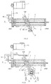
- the turnpike shaft drives have a Orbital spindle 1, stored in a stationary housing 3.
- the driver 5 is with the boom shaft 9 basically by a lever still to be described, such as through whose central axis B is basically shown in Fig. 1.
- the spindle 1 is connected to a spindle drive, preferably comprising an electric motor 11 which via Toothed belt 13 is operatively connected to the spindle 1.
- FIG. 2 is a configuration of a turnpike shaft drive according to the state of the art, which, starting from the basic configuration according to FIG. 1, ensures that when de-energized, i.e. if the Operating current of the drive fails, the turnstile in top position is blocked.
- Reference numerals as used in Fig. 1. The active connection between the slave cam 7 on the driver 5 and the Turnpike shaft 9 takes place via a lever 10 A, which a preferably open slot 12A for has the cam 7.
- the slot 12A is relative to that Lever center axis B against that end part of the spindle 1 bent so that it, as shown, in the upper Turnpike position at least approximated parallel to spindle 1 is what position when the barrier is raised, is started according to the rotating arrow.
- the slotted lever 10A is detachable with the boom shaft connected.
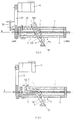
- a lever 10B is provided, which, preferably again open on one side, one parallel to lever axis B. Has slot 12B. Added to this is spindle 1 self-locking in itself or in the considered top position inhibited, such as by a weight driven in the locking lever 15 engaging the drive.
- FIG. 4 shows the inventive one provided for this Drive configuration shown.
- the lever 10B ' is similar to a torsion spring acting power stop connected. This is on the Barrier wave applied directly, or the lever is like shown in Fig. 4, two-armed, and the Storage force is applied outside of Turnpike wave preferably on the second arm.
- On this arm of the lever 10B ' is a further lever 19 articulated at 21 and carries one into it Hole 17 protruding square 23. Between square 23 and the The edges of opening 17 are, for example, four Rubber buffer elements 18.
- An optionally provided stop 15 is for the here addressed case, as shown with 15 ', in de-energized State extended.
- the Locking lever 15 'engaged as shown schematically the mechanical operative connection 27 is shown in FIG. 4, or a stop 25 'is arranged, which over the Spring storage element a complete lowering of the Barrier prevents the peak load for a complete tension of the spring element is too small.
- FIG. 5 shows the turnpike drive configuration according to the invention shown that meets this criterion. This is, based on the drive configuration according to FIG. 3, achieved in that when the barrier is raised against a spring element 29 is operated, as shown in FIG. 5 is shown schematically.
- FIG. 6 A first possibility of a drive according to the invention, which fulfills this requirement is shown in FIG. 6. It a lever 10C is provided, which the boom shaft 9th connects the driver cam 7 on the driver 5 of the spindle 1.
- the lever in turn preferably has one side open slot 12C, which, starting from the articulation area the boom shaft 9, first one parallel to the lever axis B. extending first region, then curved in Bends towards the upper end position of the driver 5 and finally, in a third area, again is bent back.
- blocking in the lower position can result from a self-locking spindle using any Lever shape or by using a lever with in the lower end position to the spindle 1 parallel driving slot respectively.
- a self-locking spindle 1 can, like this is shown schematically at 32 in FIG. 7, also by a locking of the Drive can be realized.
- Lever 10A; 10B and 10C are provided, which the driver element 5 include on both sides and guide slots 12A; 12B; 12C have, in each of which one connected to the driving element 5 Cam 7 is guided.
- the two Lever 10A; 10B or 10C on a common shaft that rotatably connected to the boom shaft 9 or after the Assembly is connected.
- Various measures can be taken to inhibit the spindle, for example if the power supply fails. On the one hand, a smaller pitch of the spindle thread can be used. On the other hand, the braking and locking devices described are used. A drive or electric motor 11, which blocks in the event of a power failure, can preferably be used. Means for realizing clutches and brakes (usually part stationary) are known to the person skilled in the art from [1] , Section G, Chapter 4 (see Section 4.4 in particular). Spindle drives for different loads (with trapezoidal screw spindles, ball screws, etc.) are known to the person skilled in the art, for example from [1], page S126, section 9.2.3.
Landscapes
- Engineering & Computer Science (AREA)
- Mechanical Engineering (AREA)
- Architecture (AREA)
- Civil Engineering (AREA)
- Structural Engineering (AREA)
- Transmission Devices (AREA)
- Refuge Islands, Traffic Blockers, Or Guard Fence (AREA)
- Valve Device For Special Equipments (AREA)
- Portable Nailing Machines And Staplers (AREA)
- Shafts, Cranks, Connecting Bars, And Related Bearings (AREA)
- Connection Of Motors, Electrical Generators, Mechanical Devices, And The Like (AREA)
- Breeding Of Plants And Reproduction By Means Of Culturing (AREA)
- Constitution Of High-Frequency Heating (AREA)
Description
- Fig. 1
- das Grundmodul eines Schlagbaum- Wellenantriebs;
- Fig. 2
- schematisch eine Ausführung des Antriebes, in Darstellung ausgehend von derjenigen von Fig. 1 gemäss dem Stand der Technik;
- Fig. 3
- analog zu Fig. 2, die Darstellung einer ersten erfindungsgemässen Ausführungsform;
- Fig. 4
- ausgehend von der Ausführungsform gemäss Fig. 3, deren Weiterbildung;
- Fig. 5
- wiederum ausgehend vom Antrieb gemäss Fig. 3, eine weitere Weiterbildung des Antriebes;
- Fig. 6
- in Analogie zu Fig. 3, ausgehend von der Darstellung gemäss Fig. 1, eine zweite erfindungsgemässe Wellenantriebskonfiguration;
- Fig. 7
- ausgehend von der erfindungsgemässen Antriebskonfiguration nach Fig. 3, eine ihrer Weiterausbildungen;
- Fig. 8
- wiederum ausgehend vom Antrieb nach Fig. 3, eine weitere Weiterausbildung.
Claims (10)
- Schlagbaum-Wellenantrieb, bei dem umfasst sind:a) eine motorisch getriebene Umlaufspindel (1), durch die ein mit einem Nocken (7) versehenes Mitnehmerorgan (5) entlang der Achse (A) der Umlaufspindel (1) verschiebbar ist,b) einen mit einem Führungsschlitz (12A; 12B; 12C) versehenen Hebel (10A; 10B; 10C), der über den offenen oder geschlossenen Führungsschlitz (12A; 12B; 12C) und den darin geführten Nocken (7) einseitig mit dem Mitnehmerorgan (5) wirkverbunden ist und der anderseitig drehfest mit einer Schlagbaumwelle (9) verbindbar ist,
dadurch gekennzeichnet, dassc) der Führungsschlitz (12B) parallel zur Mittenachse (B) des Hebels (10B) verlauft oderd) der Führungsschlitz ( 12C), in einem ersten Abschnitt parallel zur Mittenachse (B) des Hebels (10C), in einem zweiten Abschnitt gebogen nach aussen und in einem dritten Abschnitt wieder rückgebogen verlauft. - Antrieb nach Anspruch 1,
dadurch gekennzeichnet, dass
der Führungsschlitz (12C) derart gebogen verlauft, dass zumindest in einem Winkelbereich (w0) bei der Drehung desHebels (10C) ein Bereich des Führungsschlitzes (12C) zumindest annähernd parallel zur Umlaufspindel (1) verläuft, so dass eine Verschiebung des Mitnehmerorgans (5) in diesem Bereich zu keiner Drehung des Hebels (10C) und ein auf den Hebel (10C) ausgeübtes Drehmoment zu keiner axialen Verschiebung des Mitnehmerorgans (5) führt. - Antrieb nach Anspruch 2,
dadurch gekennzeichnet, dass
der Nocken (7) bei angehobenem, vollständig und/oder teilweise abgesenktem Schlagbaum in einem Bereich des Führungsschlitzes (12C) liegt, der zumindest annähernd parallel zur Umlaufspindel (1) verlauft. - Antrieb nach einem der Ansprüche 1 bis 3,
dadurch gekennzeichnet, dass
die Umlaufspindel (1) oder deren Antrieb (11) selbsthemmend ausgebildet sind. - Antrieb nach Anspruch 4 ,
dadurch gekennzeichnet, dass
zur Hemmung der Umlaufspindel (1) ein Arretierungsorgan, eine Bremse, vorzugsweise eine Magnetbremse, und/oder eine entsprechende Steigung des Spindelgewindes vorgesehen sind. - Antrieb nach Anspruch 5,
dadurch gekennzeichnet, dass
mindestens ein stromgetrieben oder stromlos ausfahrbarer Anschlag (15) für die Arretierung der Schlagbaumwelle (9) in gegebener Schwenkposition vorgesehen ist. - Antrieb nach einem der Ansprüche 1 bis 3,
dadurch gekennzeichnet, dass
die Umlaufspindel (1) und deren Antrieb (11) nicht selbsthemmend ausgebildet sind. - Antrieb nach einem der Ansprüche 1 bis 3 und 7,
dadurch gekennzeichnet, dass
ein elastischer Körper (17, 18, 19; 29; 3 4 ) vorgesehen ist, durch den auf den Hebel (10B, 10C) oder das Mitnehmerorgan (5) eine rücktreibende Kraft ausgeübt wird. - Antrieb nach Anspruch 8,
dadurch gekennzeichnet, dass
die elastischen Körper (17, 18, 19; 29; 34) Federelemente oder Kunststoffelemente sind, auf die der Hebel (10B, 10C) oder das Mitnehmerorgan (5) auf der einen und/oder anderen Seite im Bereich seiner Endauslenkung eine Kraft ausübt. - Antrieb nach einem der Anspruche 1 bis 9,
dadurch gekennzeichnet, dass
das Mitnehmerorgan (5) beidseitig mit einem Hebel (10B; 10C) wirkverbunden ist und dass die beidseitig vorgesehenen Hebel (10B; 10C) vorzugsweise einen gemeinsamen Schaft aufweisen, der drehfest mit der Schlagbaumwelle (9) verbindbar ist.
Applications Claiming Priority (3)
| Application Number | Priority Date | Filing Date | Title |
|---|---|---|---|
| CH267596 | 1996-10-30 | ||
| CH267596 | 1996-10-30 | ||
| PCT/CH1997/000408 WO1998019014A1 (de) | 1996-10-30 | 1997-10-28 | Schlagbaum-wellenantrieb |
Publications (2)
| Publication Number | Publication Date |
|---|---|
| EP0935697A1 EP0935697A1 (de) | 1999-08-18 |
| EP0935697B1 true EP0935697B1 (de) | 2002-05-15 |
Family
ID=4239062
Family Applications (1)
| Application Number | Title | Priority Date | Filing Date |
|---|---|---|---|
| EP97944677A Expired - Lifetime EP0935697B1 (de) | 1996-10-30 | 1997-10-28 | Schlagbaum-wellenantrieb |
Country Status (9)
| Country | Link |
|---|---|
| EP (1) | EP0935697B1 (de) |
| AT (1) | ATE217660T1 (de) |
| CZ (1) | CZ293192B6 (de) |
| DE (1) | DE59707301D1 (de) |
| HU (1) | HU222781B1 (de) |
| PL (1) | PL188176B1 (de) |
| SI (1) | SI9720054B (de) |
| SK (1) | SK285775B6 (de) |
| WO (1) | WO1998019014A1 (de) |
Cited By (4)
| Publication number | Priority date | Publication date | Assignee | Title |
|---|---|---|---|---|
| DE102009014645B3 (de) * | 2009-03-24 | 2010-08-12 | Siemens Aktiengesellschaft | Schlagbaum-Wellenantrieb |
| DE102014218883A1 (de) | 2014-09-19 | 2016-03-24 | Siemens Aktiengesellschaft | Verfahren zur Ermittlung der Position eines Schlagbaumes bei einem Schlagbaum-Wellenantrieb und Schlagbaum-Wellenantrieb |
| EP4538201A1 (de) * | 2023-10-13 | 2025-04-16 | BelFox Torautomatik GmbH | Antrieb für schrankenanlage |
| WO2025078662A1 (en) * | 2023-10-13 | 2025-04-17 | Boplan Bv | Drive for barrier system |
Families Citing this family (1)
| Publication number | Priority date | Publication date | Assignee | Title |
|---|---|---|---|---|
| DE10148293A1 (de) * | 2001-09-29 | 2003-04-24 | Landert Motoren Ag | Flügeltürantrieb mit Federschliessung |
Family Cites Families (2)
| Publication number | Priority date | Publication date | Assignee | Title |
|---|---|---|---|---|
| FR2559199B1 (fr) * | 1984-02-06 | 1988-08-26 | Ready Metal Manufacturing Cy | Dispositif d'ouverture et de fermeture de portillons |
| AT402311B (de) * | 1995-03-20 | 1997-04-25 | Skidata Gmbh | Absperreinrichtung |
-
1997
- 1997-10-28 HU HU0001018A patent/HU222781B1/hu not_active IP Right Cessation
- 1997-10-28 PL PL97332971A patent/PL188176B1/pl not_active IP Right Cessation
- 1997-10-28 DE DE59707301T patent/DE59707301D1/de not_active Expired - Lifetime
- 1997-10-28 SK SK539-99A patent/SK285775B6/sk not_active IP Right Cessation
- 1997-10-28 AT AT97944677T patent/ATE217660T1/de active
- 1997-10-28 EP EP97944677A patent/EP0935697B1/de not_active Expired - Lifetime
- 1997-10-28 WO PCT/CH1997/000408 patent/WO1998019014A1/de not_active Ceased
- 1997-10-28 CZ CZ19991523A patent/CZ293192B6/cs not_active IP Right Cessation
- 1997-10-28 SI SI9720054A patent/SI9720054B/sl not_active IP Right Cessation
Cited By (4)
| Publication number | Priority date | Publication date | Assignee | Title |
|---|---|---|---|---|
| DE102009014645B3 (de) * | 2009-03-24 | 2010-08-12 | Siemens Aktiengesellschaft | Schlagbaum-Wellenantrieb |
| DE102014218883A1 (de) | 2014-09-19 | 2016-03-24 | Siemens Aktiengesellschaft | Verfahren zur Ermittlung der Position eines Schlagbaumes bei einem Schlagbaum-Wellenantrieb und Schlagbaum-Wellenantrieb |
| EP4538201A1 (de) * | 2023-10-13 | 2025-04-16 | BelFox Torautomatik GmbH | Antrieb für schrankenanlage |
| WO2025078662A1 (en) * | 2023-10-13 | 2025-04-17 | Boplan Bv | Drive for barrier system |
Also Published As
| Publication number | Publication date |
|---|---|
| ATE217660T1 (de) | 2002-06-15 |
| SK53999A3 (en) | 2000-01-18 |
| WO1998019014A1 (de) | 1998-05-07 |
| HUP0001018A3 (en) | 2002-01-28 |
| HUP0001018A2 (hu) | 2000-08-28 |
| DE59707301D1 (de) | 2002-06-20 |
| CZ293192B6 (cs) | 2004-02-18 |
| HU222781B1 (hu) | 2003-10-28 |
| SI9720054B (sl) | 2002-02-28 |
| PL332971A1 (en) | 1999-10-25 |
| PL188176B1 (pl) | 2004-12-31 |
| EP0935697A1 (de) | 1999-08-18 |
| SI9720054A (sl) | 1999-06-30 |
| SK285775B6 (sk) | 2007-08-02 |
| CZ152399A3 (cs) | 2000-03-15 |
Similar Documents
| Publication | Publication Date | Title |
|---|---|---|
| DE69703635T2 (de) | Angetriebene Verriegelungsvorrichtung für Fahrzeuge mit verbesserten Mitteln zur Begrenzung der Bewegung eines Riegels | |
| DE2937961C2 (de) | Vorrichtung zum Verstellen eines Spiegelglasträgers eines Kraftfahrzeugrückspiegels | |
| DE3913995C2 (de) | ||
| EP0991832A1 (de) | Drehfallenschloss, insbesondere für kraftfahrzeuge | |
| DE4403574C1 (de) | Antriebsvorrichtung für ein zwischen Endstellungen verstellbares Teil eines Fahrzeuges | |
| DE3102402A1 (de) | Sitzverstellung, insbesondere fuer einen kraftfahrzeugsitz | |
| DE2845844A1 (de) | Antriebsvorrichtung fuer die verriegelung von autotueren | |
| DE102020122359A1 (de) | Angetriebene scharnierbaugruppe für fahrzeugtüren | |
| DE19861273B4 (de) | Spindel- oder Schneckenantrieb für Verstelleinrichtungen in Kraftfahrzeugen | |
| EP0935697B1 (de) | Schlagbaum-wellenantrieb | |
| DE2852187C2 (de) | ||
| EP3656960B1 (de) | Stellglied und lagerungseinrichtung für eine klappe | |
| DE19702083C1 (de) | Türsystem, insbesondere für ein Passagierflugzeug | |
| EP0940531A1 (de) | Schliesshilfe für Türen oder Klappen eines Kraftfahrzeuges | |
| EP1504168A1 (de) | Elektromotorischer stellantrieb | |
| DE10226355B3 (de) | Betätigungsvorrichtung | |
| DE3633010A1 (de) | Spiegelvorrichtung fuer ein fahrzeug | |
| EP0490341A1 (de) | Hubantrieb zur elektrischen Betätigung einer Fensterscheibe oder eines Schiebedachs eines Kraftfahrzeugs | |
| EP1072749A2 (de) | Elektromechanischer Antrieb für eine Drehsäule zur Bewegung eines Türflügels einer Innenschwenk- oder Aussenschwingtür an einem Fahrzeug, insbesondere einem öffentlichen Verkehrsmittel | |
| DE2943966A1 (de) | Antriebsvorrichtung fuer scheibenwischer von fahrzeugen, insbesondere kraftfahrzeugen | |
| DE4030594C2 (de) | ||
| DE102019109827B4 (de) | Aktuatorsystem für eine Rückblickvorrichtung eines Fahrzeugs | |
| DE19861278B4 (de) | Spindel- oder Schneckenantrieb für Verstelleinrichtungen in Kraftfahrzeugen | |
| EP1226372B1 (de) | Möbelantrieb | |
| DE19617226C2 (de) | Abschaltvorrichtung für den Antrieb eines zwischen Endstellungen verstellbaren Teils eines Fahrzeuges |
Legal Events
| Date | Code | Title | Description |
|---|---|---|---|
| PUAI | Public reference made under article 153(3) epc to a published international application that has entered the european phase |
Free format text: ORIGINAL CODE: 0009012 |
|
| 17P | Request for examination filed |
Effective date: 19990531 |
|
| AK | Designated contracting states |
Kind code of ref document: A1 Designated state(s): AT CH DE LI |
|
| 17Q | First examination report despatched |
Effective date: 20010205 |
|
| GRAG | Despatch of communication of intention to grant |
Free format text: ORIGINAL CODE: EPIDOS AGRA |
|
| GRAG | Despatch of communication of intention to grant |
Free format text: ORIGINAL CODE: EPIDOS AGRA |
|
| GRAH | Despatch of communication of intention to grant a patent |
Free format text: ORIGINAL CODE: EPIDOS IGRA |
|
| GRAH | Despatch of communication of intention to grant a patent |
Free format text: ORIGINAL CODE: EPIDOS IGRA |
|
| GRAA | (expected) grant |
Free format text: ORIGINAL CODE: 0009210 |
|
| AK | Designated contracting states |
Kind code of ref document: B1 Designated state(s): AT CH DE LI |
|
| REF | Corresponds to: |
Ref document number: 217660 Country of ref document: AT Date of ref document: 20020615 Kind code of ref document: T |
|
| REG | Reference to a national code |
Ref country code: CH Ref legal event code: EP |
|
| REF | Corresponds to: |
Ref document number: 59707301 Country of ref document: DE Date of ref document: 20020620 |
|
| PLBE | No opposition filed within time limit |
Free format text: ORIGINAL CODE: 0009261 |
|
| STAA | Information on the status of an ep patent application or granted ep patent |
Free format text: STATUS: NO OPPOSITION FILED WITHIN TIME LIMIT |
|
| 26N | No opposition filed |
Effective date: 20030218 |
|
| REG | Reference to a national code |
Ref country code: CH Ref legal event code: PCOW Free format text: SIEMENS SCHWEIZ AG;FREILAGERSTRASSE 40;8047 ZUERICH (CH) |
|
| PGFP | Annual fee paid to national office [announced via postgrant information from national office to epo] |
Ref country code: AT Payment date: 20100915 Year of fee payment: 14 |
|
| PGFP | Annual fee paid to national office [announced via postgrant information from national office to epo] |
Ref country code: CH Payment date: 20110106 Year of fee payment: 14 Ref country code: DE Payment date: 20101220 Year of fee payment: 14 |
|
| REG | Reference to a national code |
Ref country code: CH Ref legal event code: PL |
|
| PG25 | Lapsed in a contracting state [announced via postgrant information from national office to epo] |
Ref country code: LI Free format text: LAPSE BECAUSE OF NON-PAYMENT OF DUE FEES Effective date: 20111031 Ref country code: DE Free format text: LAPSE BECAUSE OF NON-PAYMENT OF DUE FEES Effective date: 20120501 Ref country code: CH Free format text: LAPSE BECAUSE OF NON-PAYMENT OF DUE FEES Effective date: 20111031 |
|
| REG | Reference to a national code |
Ref country code: DE Ref legal event code: R119 Ref document number: 59707301 Country of ref document: DE Effective date: 20120501 |
|
| REG | Reference to a national code |
Ref country code: AT Ref legal event code: MM01 Ref document number: 217660 Country of ref document: AT Kind code of ref document: T Effective date: 20111028 |
|
| PG25 | Lapsed in a contracting state [announced via postgrant information from national office to epo] |
Ref country code: AT Free format text: LAPSE BECAUSE OF NON-PAYMENT OF DUE FEES Effective date: 20111028 |