EP0932142B1 - Integriertes System zur Sprachverbesserung in einem Fahrzeug sowie Freisprech-Mobilfunksystem - Google Patents
Integriertes System zur Sprachverbesserung in einem Fahrzeug sowie Freisprech-Mobilfunksystem Download PDFInfo
- Publication number
- EP0932142B1 EP0932142B1 EP99300462A EP99300462A EP0932142B1 EP 0932142 B1 EP0932142 B1 EP 0932142B1 EP 99300462 A EP99300462 A EP 99300462A EP 99300462 A EP99300462 A EP 99300462A EP 0932142 B1 EP0932142 B1 EP 0932142B1
- Authority
- EP
- European Patent Office
- Prior art keywords
- far
- microphone
- signal
- input signal
- echo
- Prior art date
- Legal status (The legal status is an assumption and is not a legal conclusion. Google has not performed a legal analysis and makes no representation as to the accuracy of the status listed.)
- Expired - Lifetime
Links
- 230000001413 cellular effect Effects 0.000 title claims description 68
- 230000009467 reduction Effects 0.000 claims description 51
- 230000003044 adaptive effect Effects 0.000 claims description 42
- 230000004044 response Effects 0.000 claims description 15
- 230000014509 gene expression Effects 0.000 claims description 14
- 230000005540 biological transmission Effects 0.000 claims description 10
- 238000005070 sampling Methods 0.000 claims description 8
- 238000012935 Averaging Methods 0.000 claims description 3
- 238000010586 diagram Methods 0.000 description 13
- 238000000034 method Methods 0.000 description 12
- 238000005562 fading Methods 0.000 description 8
- URWAJWIAIPFPJE-YFMIWBNJSA-N sisomycin Chemical compound O1C[C@@](O)(C)[C@H](NC)[C@@H](O)[C@H]1O[C@@H]1[C@@H](O)[C@H](O[C@@H]2[C@@H](CC=C(CN)O2)N)[C@@H](N)C[C@H]1N URWAJWIAIPFPJE-YFMIWBNJSA-N 0.000 description 8
- 238000001914 filtration Methods 0.000 description 7
- 230000005236 sound signal Effects 0.000 description 4
- 238000013459 approach Methods 0.000 description 3
- 238000012545 processing Methods 0.000 description 3
- 230000009471 action Effects 0.000 description 2
- 230000006978 adaptation Effects 0.000 description 2
- 230000008859 change Effects 0.000 description 2
- 230000005574 cross-species transmission Effects 0.000 description 2
- 230000001419 dependent effect Effects 0.000 description 2
- 238000002592 echocardiography Methods 0.000 description 2
- 230000006870 function Effects 0.000 description 2
- 238000001228 spectrum Methods 0.000 description 2
- 230000001010 compromised effect Effects 0.000 description 1
- 238000011161 development Methods 0.000 description 1
- 230000002708 enhancing effect Effects 0.000 description 1
- 230000008569 process Effects 0.000 description 1
- 230000008054 signal transmission Effects 0.000 description 1
- 230000002123 temporal effect Effects 0.000 description 1
- 230000009466 transformation Effects 0.000 description 1
Images


Classifications
-
- G—PHYSICS
- G10—MUSICAL INSTRUMENTS; ACOUSTICS
- G10L—SPEECH ANALYSIS TECHNIQUES OR SPEECH SYNTHESIS; SPEECH RECOGNITION; SPEECH OR VOICE PROCESSING TECHNIQUES; SPEECH OR AUDIO CODING OR DECODING
- G10L21/00—Speech or voice signal processing techniques to produce another audible or non-audible signal, e.g. visual or tactile, in order to modify its quality or its intelligibility
- G10L21/02—Speech enhancement, e.g. noise reduction or echo cancellation
- G10L21/0208—Noise filtering
- G10L21/0216—Noise filtering characterised by the method used for estimating noise
- G10L2021/02161—Number of inputs available containing the signal or the noise to be suppressed
- G10L2021/02166—Microphone arrays; Beamforming
Definitions
- the invention relates to vehicle voice enhancement systems and hands-free cellular telephone systems using microphones mounted throughout a vehicle to sense driver and/or passenger speech.
- the invention relates to improvements in the selection of transmitted microphone signals and noise reduction filtering.
- a vehicle voice enhancement system uses intercom systems to facilitate conversations of passengers sitting within different zones of a vehicle.
- a single channel voice enhancement system has a near-end zone and a far-end zone with one speaking location in each zone.
- a near-end microphone senses speech in the near-end zone and transmits a voice signal to a far-end loudspeaker.
- the far-end loudspeaker outputs the voice signal into the far-end zone, thereby enhancing the ability of a driver and/or passenger in the far-end zone to listen to speech occurring in the near-end zone even though there may be substantial background noise within the vehicle.
- a far-end microphone senses speech in the far-end zone and transmits a voice signal to a near-end loudspeaker that outputs the voice signal into the near-end zone.
- Voice enhancement systems not only amplify the voice signal, but also bring an acoustic source of the voice signal closer to the listener.
- Microphones are typically mounted within the vehicle near the usual speaking locations, such as on the ceiling of the vehicle passenger compartment above the seats or on seat belt shoulder harnesses. Inasmuch as microphones are present when implementing a vehicle voice enhancement system, it is desirable to use the voice enhancement system microphones in combination with a cellular telephone system to provide a hands-free cellular telephone system within the vehicle.
- an integrated voice enhancement system and hands-free cellular telephone system be able to transmit clear intelligible voice signals.
- This can be difficult in a vehicle because significant acoustic changes can occur quickly within the passenger compartment of the vehicle. For instance, background noise can change substantially depending on the environment around the vehicle, the speed of the vehicle, etc. Also, the acoustic plant within the passenger compartment can change substantially depending upon temperature within the vehicle and/or the number of passengers within the vehicle, etc.
- Adaptive acoustic echo cancellation as disclosed in U.S. Patent Nos. 5,033,082 and 5,602,928 and U.S. patent No. 5,706,344, can be used to effectively model various acoustic characteristics within the passenger compartment to remove annoying echoes. However, even after annoying echoes are removed, background noise within the vehicle passenger compartment can distort voice signals. Further, microphone switching can create unnatural speech patterns and annoying clicking noises.
- intelligible and natural sounding voice signals is important for voice enhancement systems, and is also important for hands-free cellular telephone systems.
- providing intelligible and natural sounding voice signals is typically more difficult for cellular telephone systems. This is because a listener on the other end of the line must be able to not only clearly hear speech from the vehicle but also must be able to easily detect whether the cellular telephone is on-line. That is, the line must not appear dead to the listeners when no speech is present in the vehicle. Also, the listener on the other end of the line is typically in a quiet environment and the presence of background vehicle noises during speech is annoying.
- Embodiments of the invention relate to an integrated vehicle voice enhancement system and hands-free cellular telephone system that implements a voice activated microphone steering technique to provide intelligible and natural sounding voice signals for both the voice enhancement aspects of the system and the hands-free cellular telephone aspects of the system.
- a voice activated microphone steering technique to provide intelligible and natural sounding voice signals for both the voice enhancement aspects of the system and the hands-free cellular telephone aspects of the system.
- Embodiments of the invention apply to both single channel (SISO) and multiple channel (MIMO) systems.
- embodiments of the invention involve the use of a microphone steering switch that inputs echo-cancelled voice signals from the microphones within the vehicle and outputs a raw telephone input signal.
- Each of the microphones in the system has the capability of switching between an "off” state and an "on” state.
- the microphones are voice activated such that a respective microphone can switch into the "on” state only when the sound level in the microphone signal (e.g. dB) exceeds a threshold switching value, thus indicating that speech is present in a speaking location near the microphone.
- the microphone steering switch outputs a raw telephone input signal which is preferably a combination of 100% of the microphone output from the microphone in the "on” state, and preferably approximately 20% of the microphone output from the microphone(s) in the "off” state.
- embodiments of the invention allow only one of the microphones to be designated as the primary microphone (i.e. switched to the "on" state) at any given time.
- Embodiments of the invention implement microphone steering techniques for the designation of primary microphone signals into the "on” state so that no two microphones are switched into the “on” state at the same time. Yet, microphone output between the "on” and “off” states fades out and cross-fades between microphones in a manner that is not annoying to the driver and/or passengers within the vehicle or a person on the other end of the cellular telephone line.
- a rather high percentage of the microphone output for the microphones in the "off" state for example approximately 20%, be transmitted so that the cellular telephone line does not appear dead to a person on the other end of the telephone line when speech is not present within the vehicle.
- embodiments of the invention apply noise reduction filters to filter out the background vehicle noise in the system microphone signals.
- noise reduction filters are important for three primary reasons:
- the noise reduction filters are applied to each of the microphone signals after the echo has been subtracted.
- a single noise reduction filter can be applied to the microphone steering switch output to remove the background noise in the outgoing cell phone signal.
- the preferred noise reduction filter includes a bank of fixed filters, preferably spanning the audible frequency spectrum, and a time-varying filter gain element ⁇ m corresponding to each fixed filter.
- the raw input signal inputs each of the fixed filters, and the output of each fixed filter z m (k) is weighted by the respective time-varying filter gain element ⁇ m .
- a summer combines the weighted and filtered input signals and outputs a noise-reduced input signal.
- the preferred noise reduction filters process the raw input signal in real time in the time domain. Therefore, the need for inverse transforms which are computationally burdensome is eliminated.
- the time-varying filter gain elements are preferably adjusted in accordance with a speech strength level for the output of each respective fixed filter.
- the noise reduction filter tracks the sound characteristics of speech present in the raw input signal over time, and gives emphasis to bands containing speech, while at the same time fading out background noise occurring within bands in which speech is not present. However, if no speech at all is present in the raw input signal, the noise reduction filter will allow sufficient signal to pass therethrough so that the cellular telephone line does not appear dead to someone on the other end of the line.
- the preferred transform is a recursive implementation of a discrete cosine transform modified to stabilize its performance on digital signal processors.
- the preferred transform i.e. Equations 1 and 2
- the preferred transform has several important properties that make it attractive for embodiments of this invention.
- the preferred transform is a completely real valued transform and therefore does not introduce complex arithmetic into the calculations as with the discrete Fourier transform (DFT). This reduces both the complexity and the storage requirements.
- DFT discrete Fourier transform
- this transform can be efficiently implemented in a recursive fashion using an IIR filter representation. This implementation is very efficient which is extremely important for voice enhancement systems where the electronic controllers are burdened with the other echo-cancellation tasks.
- the preferred transform i.e. Equations 1 and 2
- Traditional recursive-type of transforms including the "sliding" DFT transform, often suffer from filter instability problems.
- This instability is the result of round-off errors which arise when the filter parameters are implemented in the finite precision environment of a digital signal processor (DSP). More precisely, the instability is due to non-exact cancellation of the "marginally" stable poles of the filter which is caused by the parameter round-off errors.
- the preferred transform presented here is designed to overcome these problems by modifying the filter parameters according to a ⁇ factor.
- the combining of the outputs acts as an inverse transform. Therefore, an explicit inverse transform is not required. This further increases the efficiency of the transformation.
- the time-varying gain elements, ⁇ m applied to the filtered input signals also have several major improvements over the existing approaches. It should be noted that the performance of the system lies solely in the proper calculation of the gain elements ⁇ m since with unity gain elements the system output is equal to the input signal resulting in no noise reduction. Existing techniques often suffer from poor speech quality. This results from the filter's inability to adjust to rapidly varying speech giving the processed speech a "choppy" sound characteristic. The approach taken here overcomes this problem by adjusting the time-varying gain elements ⁇ m in a frequency-dependent manner to ensure a fast overall dynamic response of the system.
- the ⁇ m gains corresponding to high frequency bands are determined according to speech strength level computed from a relatively small number of filter output samples, z m (k), since high frequency signals vary quickly with time and therefore fewer outputs are needed to accurately estimate the output power.
- the ⁇ m gains corresponding to low frequency bands are computed from a larger number of filter output samples in order to accurately measure the power of low frequency signals which are slowly time-varying.
- embodiments of the invention implements microphone steering switches for multiple channel voice enhancement systems.
- a MIMO voice enhancement system typically has two or more microphones in a near-end acoustic zone and two or more microphones in a far-end acoustic zone. While the microphones in the near-end zone are typically not acoustically coupled to the microphones in the far-end zone, microphones within the near-end zone may be acoustically coupled to one another and microphones within the far-end zone may be acoustically coupled to one another.
- a similar steering switch is provided to generate a transmitted near-end input signal from the far-end microphone signals.
- microphones in the "off" state contribute a small percentage of the microphone output, such as 5%-10% or less, so that transmission of background noise through the voice enhancement system is not noticeable by the driver and/or passengers within the vehicle. It is desirable that a small undetectable percentage of the microphone output be contributed to the respective input signal to prevent annoying microphone clicking that would occur if the microphone switches electrically between being on and being completely off.
- Fig. 1 illustrates an integrated vehicle voice enhancement system and hands-free cellular telephone system 10 in accordance with an embodiment of the invention.
- the system 10 has a near-end zone 12 and a far-end zone 14, both residing within a vehicle 15.
- Each zone 12 and 14 may be subject to substantial background noises.
- a passenger in the vehicle seated in the far-end zone 14 may have difficulty hearing a passenger and/or driver located in the near-end zone 12 without the use of a vehicle voice enhancement system, or vice-versa.
- the near-end zone 12 includes two speaking locations 16 and 18, respectively.
- a first near-end microphone 20 senses noise and speech at speaking location 16.
- a second near-end microphone 22 senses noise and speech at speaking location 18.
- a first near-end loudspeaker 24 introduces sound into the near-end zone 12 at speaking location 16.
- a second near-end loudspeaker 26 introduces sound into the near-end zone 12 at speaking location 18. It is preferred that the first near-end microphone 20 be located in close proximity to the first speaking location 16 in the near-end acoustic zone 12, such as on the ceiling of the vehicle 15 directly above the speaking location 16 or on a seat belt worn by a driver or passenger located in speaking location 16.
- the second near-end microphone 22 be located in close proximity to the second near-end speaking location 18 in the near-end acoustic zone 12. Because of the close proximity between speaking locations 16 and 18, the microphones 20 and 22 in the near-end zone will typically be coupled acoustically. For instance, sound present at speaking location 16 in the near-end zone 12 is detected primarily by the first microphone 20 but can also be detected to some extent by the second microphone 22 in the near-end zone 12, and vice-versa.
- the first near-end microphone 20 generates a first near-end voice signal that is transmitted through line 28 to an electronic controller 30.
- the second near-end microphone 22 generates a second near-end voice signal that is transmitted through line 32 to the electronic controller 30.
- the far-end zone 14 in the vehicle 15 includes a first speaking location 34 and a second speaking location 36.
- a first far-end microphone 38 senses noise and speech at speaking location 34.
- a second far-end microphone 40 senses noise and speech at speaking location 36.
- a first far-end loudspeaker 42 introduces sound into the far-end zone 14 at speaking location 34.
- a second far-end loudspeaker 44 introduces sound into the far-end zone 14 at speaking location 36.
- the first far-end microphone 38 generates a first far-end voice signal in response to noise and speech present at speaking location 34.
- the first far-end voice signal is transmitted through line 46 to the electronic controller 30.
- the second far-end microphone 40 generates a second far-end voice signal in response to noise and speech present at speaking location 36.
- the second far-end voice signal is transmitted through line 48 to the electronic controller 30. It is preferred that the first far-end microphone 38 be located in close proximity to the first far-end speaking location 34 in the far-end acoustic zone. Likewise, it is preferred that the second far-end microphone 40 be located in close proximity to the second far-end speaking location 36 in the far-end zone 14.
- the first far-end microphone 38 and the second far-end microphone 40 are acoustically coupled inasmuch as speech present at speaking location 34 is sensed primarily by the first far-end microphone 38 but is also sensed to some extent by the second far-end microphone 40, and vice-versa.
- the electronic controller 30 outputs a first near-end input signal in line 50 that is transmitted to the first near-end loudspeaker 24.
- the electronic controller 30 also outputs a second near-end input signal that is transmitted through line 52 to the second near-end loudspeaker 26.
- the electronic controller outputs a first far-end input signal that is transmitted through line 54 to the first far-end loudspeaker 42.
- the electronic controller also outputs a second far-end input signal that is transmitted through line 56 to the second far-end loudspeaker 44.
- Fig. 1 also shows a cellular telephone 58 integrated into the system 10.
- the electronic controller 30 outputs a telephone input signal Tx out that is transmitted through line 60 to the cellular telephone 58.
- the electronic controller 30 also receives a telephone receive signal Rx in from the cellular telephone through line 62. In this manner, the electronic controller 30 communicates with the cellular telephone 58 to provide for a hands-free cellular telephone system within the vehicle 16.
- Figs. 2A and 2B explain voice activated switching as preferably implemented for both the near-end microphones 20 and 22 and the far-end microphones 38 and 40.
- Fig. 2A illustrates microphone input in terms of sound level (dB)
- Fig. 2B illustrates voice activated switching of microphone output between an "off" state and an "on” state in relation to the microphone input shown in Fig. 2A.
- Microphone input sound level (dB) is preferably determined using a short-time, average magnitude estimating function to detect whether speech is present. Other suitable estimating functions are disclosed in Digital Processing of Speech Signals , Lawrence R. Raviner, Ronald W. Schafer, 1978, Bell Laboratories, Inc., Prentice Hall, pages 120-126.
- the electronic controller 30 While each microphone 20, 22, 38 and 40 transmits a full signal to the electronic controller 30, the electronic controller 30 includes a gate/switch that reduces the transmission of a respective microphone signal at least when the sound level for the signal does not exceed the threshold switching value.
- Fig. 2A illustrates that background noise present within the vehicle, time periods 64A, 64B, 64C and 64D, generally has a sound level less than a threshold switching value depicted by dashed line 66.
- speech present during time periods 68A and 68B generally has a sound level exceeding the threshold switching value 66.
- Microphone output remains in an "off" state before speech is sensed by a respective microphone.
- Microphone output switches into an "on” state once speech is present in a speaking location associated with the microphone, given that no other microphones are switched into an “on” state.
- Fig. 2B shows microphone output initially in an “off” state, reference 70, which corresponds to time period 64A in Fig. 2A in which only background noise is present in the microphone signal. Note that in the "off” state 70, microphone output is preferably set to approximately 20% of the microphone output in the "on” state.
- Fig. 2B shows microphone output switching to an "on” state 72 when speech is present and microphone input exceeds the threshold switching value 66, region 68A in Fig. 2A.
- Microphone input sound level (dB) is preferably measured in approximately 12 millisecond windows, thus a microphone can be switched into the "on” state at a rate faster than is perceptible during normal conversation.
- Fig. 2B further illustrates that microphone output remains in an "on” state even if the microphone input sound level falls below the threshold switching value 66 for a relatively short amount of time. That is, microphone output holds in an "on” state for at least a holding time period t H , which is preferably equal to approximately one second. Once the microphone input sound level drops below the threshold switching value 66 for more than the holding time period t H , the microphone output fades 74 from the "on" state 72 to the "off” state 76. It is desirable that microphone output when the microphone is in the "off” state be greatly reduced, e.g. approximately 20% or less for cellular telephone transmission and approximately 1%-10% for voice enhancement transmission, but not completely eliminated.
- the background noise that is present on the signal corresponding to the microphone in the "on" state is also problematic for Tx out , since the listener on the other end of the line is typically in a quiet environment making such noise objectionable.
- the telephone input signal Tx out be filtered to remove the background noise before transmission of the signal to the cellular telephone 58.
- Fig. 3A illustrates a single channel (SISO) integrated voice enhancement system and hands-free cellular telephone system 78 that includes a microphone steering switch 80 and a noise-reduction filter 82 for the telephone input signal Tx out .
- SISO single channel
- the SISO system 78 shown in Fig. 3A is similar to the system 10 shown in Fig. 1 and like reference numerals are used where appropriate to facilitate understanding.
- the near-end microphone 20 senses sound in the near-end zone 12 and generates a near-end voice signal that is transmitted through line 28 to a near-end echo cancellation summer 84.
- a near-end adaptive acoustic echo canceller 86 inputs the near-end input signal from line 50.
- the near-end adaptive echo canceller 86 outputs a near-end echo cancellation signal in line 88 that inputs the near-end echo cancellation summer 84.
- the near-end acoustic echo canceller 86 is preferably an adaptive finite impulse response filter having sufficient tap length to model the acoustic path between the near-end loudspeaker 24 and the output of the near-end microphone 20.
- the near-end acoustic echo canceller 86 is preferably adapted using an LMS update or the like, preferably in accordance with the techniques disclosed in copending patent application Serial No. 08/626,208, entitled "Acoustic Echo Cancellation In An Integrated Audio And Telecommunication Intercom System", by Brian M. Finn, filed on March 29, 1996, now U.S. Patent No.
- the near-end echo cancellation summer 84 subtracts the near-end echo cancellation signal in line 88 from the near-end voice signal in line 28, and outputs an echo-cancelled, near-end voice signal in line 90.
- the near-end echo cancellation summer 84 thus subtracts from the near-end voice signal in line 28 that portion of the signal due to sound introduced by the near-end loudspeaker 24.
- the echo-cancelled, near-end voice signal in line 90 is transmitted both to a far-end input summer 92 and through line 94 to the microphone steering switch 80.
- the far-end input signal 92 also receives components of the far-end input signal other than the echo-cancelled near-end voice signal, such as a cellular telephone receive signal Rx in from line 96 or an audio feed (not shown), etc.
- the far-end input summer 92 outputs the far-end input signal in line 54 which drives the far-end loudspeaker 42.
- the far-end microphone 38 senses sound in the far-end zone 14 at speaking location 34 and generates a far-end voice signal that is transmitted through line 46 to a far-end echo cancellation summer 98.
- a far-end adaptive acoustic echo canceller 100 preferably identical to the near-end adaptive acoustic echo canceller 86, receives the far-end input signal in line 54 and outputs a far-end echo cancellation signal in line 102.
- the far-end echo cancellation signal in line 102 inputs the far-end echo cancellation summer 98.
- the far-end echo cancellation summer 98 subtracts the near-end echo cancellation signal in line 102 from the far-end voice signal in line 46 and outputs an echo-cancelled, far-end voice signal in line 104.
- the far-end echo cancellation summer 98 thus subtracts from the far-end voice signal in line 46 that portion of the signal due to sound introduced by the far-end loudspeaker 42.
- the echo-cancelled, far-end voice signal in line 104 is transmitted to both a near-end input summer 106, and to the microphone steering switch 80 through line 108.
- a privacy switch 110 is located in line 108, thus allowing a passenger or driver within the vehicle to discontinue transmission of the far-end echo-cancelled voice signal to the microphone steering switch 80 by opening the privacy switch 110.
- a similar privacy switch 112 is located in line 96 between the cellular telephone 58 and the far-end input summer 92 which enables a driver and/or passenger within the vehicle to discontinue transmission of the telephone receive signal Rx in from the cellular telephone 58 to the far-end loudspeaker 42 in the far-end zone 14.
- the near-end input summer 106 also receives other components of the near-end input signal, such as the cellular telephone receive signal Rx in in line 114 or an audio feed (not shown), etc.
- the near-end input summer 106 outputs the near-end input signal in line 50 which drives the near-end loudspeaker 20.
- the microphone steering switch 80 receives both the echo-cancelled near-end voice signal through line 94 and the echo-cancelled far-end voice signal through line 108.
- the microphone steering switch 80 combines and/or mixes the echo-cancelled voice signals preferably in the manner described with respect to Figs. 4-7, and outputs a raw telephone input signal in line 116.
- the raw telephone input signal 116 inputs the noise reduction filter 82.
- the noise reduction filter 82 outputs a noise-reduced telephone input signal Tx out that inputs the cellular telephone 58.
- Fig. 3B illustrates a single channel (SISO) integrated voice enhancement system and hands-free cellular telephone system 78a which is similar to the system 78 shown in Fig. 3A.
- the primary difference in the system 78a in Fig. 3B is that the single noise reduction filter 82 in the system 78 shown in Fig. 3A has been replaced by a plurality of noise reduction filters 82a, 82b.
- Noise reduction filter 82a is located in the near-end voice signal line 90.
- Noise reduction filter 82b is located in the far-end voice signal line 104.
- this implementation also removes the background noise in the voice signals themselves.
- Noise reduction filter 82a removes the background noise in the near-end voice line 90 and therefore prevents the rebroadcasting of this noise on the far-end loudspeaker 42.
- noise reduction filter 82b removes the background noise in the far-end voice line 104 and therefore prevents the rebroadcasting of this noise on the near-end loudspeaker 24.
- the system 78a shown in Fig. 3B is similar to the system 78 shown in Fig. 3A.
- Figs. 4-7 illustrate the preferred microphone steering technique for the cellular telephone input signal which is implemented by the microphone steering switch 80.
- Fig. 4 is a state diagram for voice activated switching between the near-end microphone 20 labelled MIC 1 and the far-end microphone 38 labelled MIC 2. As shown in the state diagram of Fig. 4, only one of the microphones 20, 38 can be switched into the "on” state at any given time.
- the idle state 120 indicates a state in which both microphones 20, 38 are in an "off” state. From the idle state 120, it is possible for either the near-end microphone 20, MIC 1, to switch into an "on” state 122 or for the far-end microphone 38, MIC 2, to switch into an "on” state 124.
- FIG. 5 graphically depicts switching near-end microphone 20 output, MIC 1, into an "on" state 122 when the system is initially in the idle state 120. More specifically, the near-end microphone 20, MIC 1, senses background noise and speech within the vehicle and generates a respective microphone signal in response thereto. The magnitude of the microphone signal is determined in accordance with the voice activated switching technique illustrated in Figs. 2A and 2B. Microphone output for the microphone 20, MIC 1, is maintained in the "off” state if the magnitude of the microphone signal is below the threshold switching value 66.
- the first microphone having a microphone signal with a magnitude exceeding the threshold switching value 66 switches to the "on" state.
- Fig. 5 shows the near-end microphone 20 output switching from an "off" state 126 to an "on” state 128.
- the microphone selected to be in the "on” state is referred herein as the designated primary microphone.
- the raw telephone input signal in line 116 from the microphone steering switch 80 is preferably a combination of the full echo-cancelled voice signal from the primary microphone and approximately 20% of the echo-cancelled voice signal from the other microphone.
- the microphone output is switched to an "on” state
- the microphone holds in the "on” state even after the sound level of the microphone signal falls below the threshold switching value 66 for the holding time period t H .
- the microphone output for the primary microphone enters a fade-out state 130, Fig. 4, as long as the sound level for the other microphone does not exceed the threshold switching value 66.
- lines 122B and 124B illustrate respective microphones MIC 1 and MIC 2 entering the fade-out state 130.
- Line 130A illustrates that after the microphone completes the fade-out state 130, the system enters the idle state 120.
- Fig. 7 graphically depicts the switching action for the near-end microphone 20 output through the fade-out state 130.
- Microphone output begins in the "on” state 132, and holds in the “on” state for the holding time period 134 even after the sound level for the microphone 20 signal falls below the threshold switching value 66.
- the holding time period t H expires, the microphone 20 output enters the fade-out state 130 in which the microphone output fades from the "on" state 134 to the "off” state 136.
- the preferred fade-out time period t H is approximately three seconds.
- MIC 1 is designated as the primary microphone, state 122, or the far-end microphone 38, MIC 2 is designated as the primary microphone, state 124, and the sound level of the other microphone exceeds the threshold switching value 166, it may be desirable under some circumstances to cross-fade between the microphones as illustrated by cross-fade state 138, Fig. 4.
- Line 122C pointing towards the cross-fade state 138 illustrates the near-end microphone 20, MIC 1, as the designated primary microphone, cross-fading from the "on" state 122 to the "off" state.
- Line 124C from the cross-fade state 138 illustrates that the far-end microphone 38, MIC 2, contemporaneously fades on from the "off” state to the "on” state 124 to become the designated primary microphone.
- Figs. 6A and 6B graphically depict the switching action for the cross-fading state 138 illustrated by lines 122C and 124C and cross-fading state 138.
- Fig. 6A shows the near-end microphone 20, MIC 1, switching from the "off” state 140 to the "on” state 142 as in accordance with line 122A and state 122 in Fig. 4, thus designating the near-end microphone 20, MIC 1, as the primary microphone.
- the far-end microphone 38, MIC 2 remains in the "off" state, reference numeral 144 and 146 in Fig. 6B. If the sound level for the far-end microphone 38, MIC 2, exceeds the threshold switching value 66 after the near-end microphone 20, MIC 1, has been designated as the primary microphone (i.e. the sound level for the far-end microphone 38, MIC 2, exceeds the threshold switching value 166 during the time period designated by reference numeral 146 in Fig. 6B), the far-end microphone 38, MIC 2, is designated as a priority requesting microphone.
- the designated priority requesting microphone requests priority to become the designated primary microphone, but does not enter the "on” state until the designated primary microphone relinquishes priority, even though the sound level for the priority requesting microphone exceeds the threshold switching value 66. In other words, the designated priority switching microphone cannot become the designated primary microphone until the designated primary microphone relinquishes priority.
- reference numeral 148 in Figs. 6A and 6B the designated primary microphone (near-end microphone 20, MIC 1, in Fig. 6A) fades out from the "on" state 142 to the "off" state 150, as indicated by reference numeral 152 in Fig.
- the designated primary microphone i.e. the near-end microphone 20, MIC 1 in Fig. 6A
- the designated primary microphone relinquish priority even before the expiration of the holding time period t H if statistically it is determined that the sound level for the priority requesting microphone is sufficiently high compared to the sound level for the designated primary microphone. For instance, it may be desirable for the designated primary microphone to relinquish priority when the sound level for the priority requesting microphone exceeds the sound level for the designated priority microphone on a time-averaged basis by 50% for at least one second.
- line 124D pointing towards the cross-fade state 138 illustrates that the far-end microphone 38, MIC 2, cross-fades from the "on” state to the "off” state.
- Line 122D from the cross-fade state 138 illustrates that contemporaneously the near-end microphone 20, MIC 1, cross-fades on from the "off” state to the "on” state.
- Cross-fading from the far-end microphone 38, MIC 2, as the designated primary microphone, state 124, to the near-end microphone 20, MIC 1, as the designated primary microphone, state 122 is accomplished in the same manner as shown in Figs. 6A and 6B and as described above with respect to a cross-fade from the near-end microphone 20, MIC 1, to the far-end microphone 38, MIC 2.
- Fig. 8A illustrates the preferred noise reduction filter 82 which receives the raw telephone input signal designated as x(k) in line 116 from the microphone steering switch 80 and system 78 shown in Fig. 3A.
- the same noise reduction filter 82 is preferably used in the system 78a shown in Fig. 3B at the locations of noise reduction filters 82a, 82b to operate on the near-end and far-end voice signals, respectively.
- the following discussion relating to noise reduction filter 82 assumes that the noise reduction filter 82 is in the location shown in Fig. 3A.
- the raw telephone input signal x(k) in line 116 inputs a plurality of M fixed filters h 0 , h 1 , h 2 ...h M-2 , h M-1 .
- the plurality of fixed filters h 0 , h 1 , h 2 ...h M-2 , h M-1 preferably span the audible frequency spectrum.
- Each of the fixed filters outputs a respective filtered telephone input signal z 0 (k), z 1 (k), z 2 (k)...z M-2 (k), z M-1 (k).
- the fixed filters are preferably a reclusive implementation of a discrete cosine transform in the time domain modified to stabilize performance on digital signal processors, however, other types of fixed filters can be used in accordance with an embodiment of the invention.
- Karhunen-Loeve transforms, wavelet transforms, or even the eigen filters for an eigen filter adaptation band filter (EAB) or an eigen filter filter bank (EFB) as disclosed in U.S. Patent No. 5,561,598, entitled "Adaptive Control System With Selectively Constrained Output And Adaptation" by Michael P. Nowak et al., issued on October 1, 1996, are examples of other fixed filters that may be suitable for the noise reduction filter 82.
- the plurality of fixed filters h 0 , h 1 , h 2 ...h M-2 , h M-1 are infinite impulse response filters in which the filtered telephone input signals z 0 (k), z 1 (k), z 2 (k)...z M-2 (k), z M-1 (k) are represented by the following expressions: for fixed filter h 0 ; and for fixed filters h 1 , h 2 ...h M-2 , h M-1 ; where ⁇ is a stability parameter, x(k) is the raw telephone input signal for sampling period k, M is the number of fixed filters h 0 , h 1 , h 2 ...h M-2 , h M-1 , and z m is the filtered telephone input signal for the m th filter h 0 , h 1 , h 2 ...h M-2 , h M-1 .
- Equations 1 and 2 should be set to approximately 1, for example 0.975.
- the implementation of Equations 1 and 2 in block form is shown schematically in Figs. 8B, 8C and 8D.
- Fig. 8B (Equation 2), the blocks labelled RT 1 , RT 2 , RT 3 , RT 4 ...RT M-2 , and RT M-1 designate the recursive portions of the fixed filters h 1 , h 2 , h 3 , h 4 ...h M-2 , and h M-1 , respectively.
- FIG. 8D illustrates the implementation of RT m for the m th filter h 1 , h 2 , h 3 , h 4 ...h M-2 , and h M-1 .
- the implementation of fixed filter h 0 in accordance with Equation 1 is shown in Fig. 8C.
- the fixed filters h 0 , h 1 , h 2 ...h M-2 , h M-1 may be realized by finite impulse response filters.
- Equations 1 through 3 can be implemented efficiently, especially in the IIR form of Equations 1 and 2. From a theoretical standpoint, the Karhunen-Loeve transform is probably optimal in the sense that it orthogonalizes or decouples noisy speech signals into speech and noise components most effectively. However, the transform of Equations 1 and 2 can also be used to compute orthogonal filtered telephone input signals z 0 (k), z 1 (k), z 2 (k)...z M-2 (k), z M-1 (k) for each sample period. Further, the transform filter coefficients and the filter output are real values, therefore no complex arithmetic is introduced into the system.
- the fixed filters h 0 , h 1 , h 2 ...h M-2 , h M-1 act as a group of band pass filters to break the raw telephone input signal x(k) into M different frequency bands of the same bandwidth.
- filter h m has a band pass from about (F s /(M)) (m-.5) Hz to (F s /(2M)) (m+.5) Hz resulting in a bandwidth of F s /(2M) Hz, where F s is the sampling frequency.
- F s is the sampling frequency.
- the number of fixed filters h 0 , h 1 , h 2 ...h M-2 , h M-1 is chosen to be as large as possible and is limited to the amount of processing power available on the electronic controller 30 for a particular sampling rate. For instance, if the electronic controller 30 has a digital signal processor which is a Texas Instrument TMS320C30DSP running at 8kHz, the system should preferably have approximately 20-25 fixed filters h 0 , h 1 , h 2 ...h M-2 , h M-1 .
- Each of the filtered telephone input signals z 0 (k), z 1 (k), z 2 (k)...z M-2 (k), z M-1 (k) is weighted by a respective time-varying filter gain element ⁇ 0 (k), ⁇ 1 (k), ⁇ 2 (k)... ⁇ M-2 (k), ⁇ M-1 (k).
- Each of the time-varying filter gain elements ⁇ 0 (k), ⁇ 1 (k), ⁇ 2 (k)... ⁇ M-2 (k), ⁇ M-1 (k) is preferably determined in accordance with the following expression: where ⁇ m (k) is the value of the time-varying filter gain element associated with the m th fixed filter h 0 , h 1 , h 2 ...h M-2 , h M-1 at sampling period k, SSL m (k) is the speech strength level for the respective filtered telephone input signal z 0 (k), z 1 (k), z 2 (k)...z M-2 (k), z M-1 (k) at sampling period k, and ⁇ and ⁇ are preselected performance parameters having values greater than 0.
- s_pwr m (k) s_pwr m (k-1) + ⁇ m (z m (k) * z m (k) - s_pwr m (k-1))
- ⁇ m is a fixed time constant that is in general different for each of the M fixed filters h 0 , h 1 , h 2 ...h M-2 , h M-1
- z m (k) is the value of the respective filtered telephone inputs z 0 (k), z 1 (k), z 2 (k)...z M-2 (k), z M-1 (k) at sample period k taken when speech is present in the raw telephone
- the time constants ⁇ m are determined so that the effective length of the averaging window used to estimate the power in a particular frequency band is proportional to the center frequency of the frequency band. In other words, the time constant ⁇ m increases to yield a faster estimation of speech and noise power level as the center frequency of the band increases. This ensures a fast overall dynamic system response.
- the time constants ⁇ m are preferably less than 0.10 and greater than 0.01.
- n_pwr m (k) n_pwr m (k-1) + ⁇ 0 (z m (k) * z m (k) - n_pwr m (k-1))
- z m (k) is the value of the respective filtered telephone input signal z 0 (k), z 1 (k), z 2 (k)...z M-2 (k), z M-1 (k) at sample period k taken when speech is not present in the raw telephone input signal x(k)
- ⁇ 0 is a fixed time constant preferably set to a small value, such as ⁇ 0 equal to approximately 10 -3 . Setting fixed time constant ⁇ 0 to a small
- the noise reduction filter 82 generally has two modes of operation, a noise estimation mode and a speech filtering mode.
- the noise estimation mode background noise for each band corresponding to the fixed filters h 0 , h 1 , h 2 ...h M-2 , h M-1 is estimated.
- the noise reduction filter 82 periodically returns to the noise estimation mode when speech is not present in the raw telephone input signal x(k) (i.e. when the microphone steering switch 80 is switched to the idle state 120, Fig. 4).
- it is desirable to estimate only the stationary background noise present on the microphone signals i.e., background noise which statistically does not vary substantially over time). This is accomplished by setting a time constant ⁇ 0 equal to a small value, such as ⁇ 0 equal to approximately 10 -3 .
- the system When speech is present in the raw telephone input signal x(k), the system operates in the speech filtering mode. After estimating the combined speech and noise power level s_pwr m (k) at the sample period k for each of the filtered telephone input signals z 0 (k), z 1 (k), z 2 (k)...z M-2 (k), z M-1 (k), the respective time-varying filter gain elements ⁇ 0 (k), ⁇ 1 (k), ⁇ 2 (k)... ⁇ M-2 (k), ⁇ M-1 (k) are adjusted between 0 and 1 according to the signal-to-noise power ratio SSL m (k) corresponding to each filtered telephone input signal z 0 (k), z 1 (k), z 2 (k)...z M-2 (k), z M-1 (k), Eq.
- the corresponding gain element will be approximately one, thus passing the speech on this band. If the SSL is small, the corresponding gain element will be approximately zero, thus removing the noise in this band.
- it may be useful to set ⁇ m (k) 0 when n_pwr m (k) is greater than a preselected threshold value. In this manner, the time-varying filter gain elements ⁇ 0 (k), ⁇ 1 (k), ⁇ 2 (k)... ⁇ M-2 (k), ⁇ M-1 (k) track the characteristics of speech present within the raw telephone input signal x(k) and thereby create a more intelligible noise-reduced telephone input signal Tx out (k).
- Fig. 9A schematically illustrates the MIMO integrated vehicle voice enhancement system and hands-free cellular telephone system 10 illustrated in Fig. 1.
- the MIMO system 10 shown in Fig. 9 is similar to the SISO system 78 shown in Fig. 3, and like reference numerals will be used where helpful.
- the first near-end microphone 20 senses speech and noise present at speaking location 16 and generates a first near-end voice signal that is transmitted through line 28 to a first near-end echo cancellation summer 162A.
- the first near-end echo cancellation summer 162A also inputs a first near-end echo cancellation signal from line 164A and a third near-end echo cancellation signal from line 164C.
- the first near-end echo cancellation signal in line 164A is generated by a first near-end adaptive acoustic echo canceller AEC 11,11 .
- the first near-end adaptive echo canceller AEC 11,11 (as well as the other adaptive echo cancellers in Fig.
- AEC 11,12 , AEC 12,11 , AEC 12,12 , AEC 21,21 , AEC 21,22 , AEC 22,21 , and AEC 22,22 is preferably an adaptive FIR filter as discussed with respect to Fig. 3, and inputs a first near-end input signal in line 54 that drives the first near-end loudspeaker 24.
- the third adaptive echo canceller AEC 12,11 inputs a second near-end input signal in line 52 that drives the second near-end loudspeaker 26, and outputs the third near-end echo cancellation signal in line 164C.
- the first near-end echo cancellation summer 162A subtracts the first near-end echo cancellation signal in line 164A and the third near-end echo cancellation signal in line 164C from the first near-end voice signal in line 28 to generate a first echo-cancelled, near-end voice signal in line 166A.
- the first adaptive acoustic echo canceller AEC 11,11 adaptively models the path between the first near-end loudspeaker 24 and the output of the first near-end microphone 20.
- the third adaptive acoustic echo canceller AEC 12,11 adaptively models the path between the second near-end loudspeaker 26 and the output from the first near-end microphone 20.
- the first near-end echo cancellation summer 162A subtracts from the first near-end voice signal in line 28 that portion of the signal due to sound introduced by the first near-end loudspeaker 24, and also that portion of the signal due to sound introduced by the second near-end loudspeaker 26.
- the first echo-cancelled, near-end voice signal in line 166 is transmitted to both a far-end voice enhancement steering switch 168A and also to a telephone steering switch 80A through line 170A.
- the second near-end microphone 22 senses speech and noise present at speaking location 18 and outputs a second near-end voice signal through line 32 to a second near-end echo cancellation summer 162B.
- the second near-end echo cancellation summer 162B also receives a second near-end echo cancellation signal in line 164B and a fourth near-end echo cancellation signal in line 164D.
- the second near-end echo cancellation in line 164B is generated by a second near-end adaptive acoustic echo canceller AEC 12,12 .
- the second near-end adaptive acoustic echo canceller AEC 12,12 inputs the second near-end input signal in line 52 which drives the second near-end loudspeaker 26.
- the fourth near-end echo cancellation signal in line 164D is generated by a fourth near-end adaptive acoustic echo canceller AEC 11,12 .
- the fourth near-end adaptive acoustic echo canceller AEC 11,12 inputs the first near-end input signal in line 54 that drives the first near-end loudspeaker 24.
- the second near-end echo cancellation summer 162B subtracts the second near-end echo cancellation signal in line 164B and the fourth near-end echo cancellation signal in line 164D from the second near-end voice signal in line 32 to generate a second echo-cancelled, near-end voice signal in line 166B.
- the second near-end adaptive acoustic echo canceller AEC 12,12 adaptively models the path between the second near-end loudspeaker 26 and the output of the second near-end microphone 22.
- the fourth near-end adaptive acoustic echo canceller AEC 11,12 adaptively models the path between the first near-end loudspeaker 24 and the output of the second near-end microphone 22.
- the second near-end echo cancellation summer 162B subtracts from the second near-end voice signal in line 32 that portion of the signal due to sound introduced by the second near-end loudspeaker 26, and also that portion of the signal due to sound introduced by the first near-end loudspeaker 24.
- the second echo-cancelled, near-end voice signal in line 166B is transmitted to both the far-end voice enhancement steering switch 168A, and to the telephone steering switch 80A through line 170B.
- the first far-end microphone 38 senses speech and noise present at speaking location 34 within the far-end zone 14 and generates a first far-end voice signal that is transmitted through line 46 to a first far-end echo cancellation summer 172A.
- the first far-end echo cancellation summer 172A also inputs a first far-end echo cancellation signal from line 174A and a third far-end echo cancellation signal from line 174C.
- the first far-end echo cancellation signal in line 174A is generated by a first far-end adaptive acoustic echo canceller AEC 21,21 .
- the first far-end adaptive acoustic echo canceller AEC 21,21 inputs a first far-end input signal in line 54 that drives the first far-end loudspeaker 42.
- the third far-end echo cancellation signal in line 174C is generated by the third far-end adaptive acoustic echo canceller AEC 22,21 .
- the third far-end adaptive echo canceller AEC 22,21 inputs a second far-end input signal in line 56 that also drives the second far-end loudspeaker 44.
- the first far-end adaptive acoustic canceller AEC 21,21 models the path between the first far-end loudspeaker 42 and the output of the first far-end microphone 38.
- the third far-end adaptive acoustic echo canceller AEC 22,21 models the path between the second far-end loudspeaker 44 and the output of the first far-end microphone 38.
- the first far-end echo cancellation summer 172 subtracts the first far-end echo cancellation signal in line 174A and the third far-end echo cancellation signal in line 174C from the first far-end voice signal in line 46 to generate a first echo cancelled, far-end voice signal in line 176A.
- the first echo-cancelled, far-end voice signal in line 176A is transmitted both to a near-end voice enhancement steering switch 168B, and also to the telephone steering switch 80A through line 170C.
- the second far-end microphone 40 senses speech and noise present at speaking location 36 in the far-end zone 14 and generates a second far-end voice signal that is transmitted to a second far-end cancellation summer 172B through line 48.
- a second far-end echo cancellation signal in line 174B and a fourth far-end echo cancellation signal in line 174D also input the second far-end echo cancellation summer 172B.
- the second far-end echo cancellation signal in line 174B is generated by a second far-end adaptive acoustic echo canceller AEC 22,22 .
- the second far-end adaptive acoustic echo canceller AEC 22,22 inputs the second far-end input signal in line 56 which also drives the second far-end loudspeaker 44.
- the second far-end adaptive acoustic echo canceller AEC 22,22 models the path between the second far-end loudspeaker 44 and the output of the second microphone 40.
- the fourth far-end echo cancellation signal in 174D is generated by a fourth far-end adaptive acoustic echo canceller AEC 21,22 .
- the fourth far-end adaptive acoustic echo canceller AEC 21,22 inputs the first far-end input signal in line 54 that drives the first far-end loudspeaker 42.
- the fourth far-end adaptive acoustic echo canceller AEC 21,22 models the path between the first far-end loudspeaker 42 and the output of the second far-end microphone 40.
- the second far-end echo cancellation summer 172B subtracts the second echo cancellation signal in line 174B and the fourth echo cancellation signal in line 174D from the second far-end voice signal in line 48 to generate a second echo-cancelled, far-end voice signal in line 176B.
- the second echo-cancelled, far-end voice signal in line 176B is transmitted to both the near-end voice enhancement steering switch 168B, and also to the telephone steering switch 80A through line 170D.
- the telephone steering switch 80A outputs a raw telephone input signal in line 116 preferably in accordance with the state diagram shown in Fig. 10.
- the raw telephone input signal in line 116 inputs the noise reduction filter 82, which is preferably the same as the filter shown in Fig. 8.
- the noise reduction filter 82 outputs a noise-reduced telephone input signal Tx out (k) to the cellular telephone 58.
- the cellular telephone 58 outputs a telephone receive signal Rx in in line 178 that is eventually transmitted to the loudspeakers 24, 26, 42, and 44 in the system 10.
- Fig. 9A shows the telephone receive signal Rx in inputting block 168A, 168B which schematically illustrates both the near-end voice enhancement steering switch 168A and the far-end voice enhancement steering switch 168B.
- the far-end voice enhancement steering switch 168A operates generally in the same manner as the steering switch 80 shown in Fig. 3 and described in conjunction with Figs. 4 and 7, however, microphone output in the "off" state for the far-end voice enhancement steering switch 168A preferably sets microphone output to 10% or less, rather than approximately 20%.
- the far-end voice enhancement steering switch 168A thus selects and mixes the first and second echo-cancelled, near-end voice signals in line 166A and 166B and generates a far-end voice enhancement input signal in line 180A.
- both of the near-end microphones 20 and 22 are likely to sense speech from a single passenger and/or driver located in the near-end acoustic zone 12, especially if the driver and/or passenger is not located in close proximity to one of the microphones 20, 22 or the driver and/or passenger is speaking loudly (i.e., both of the near-end microphones 20, 22 are acoustically coupled to one another).
- Fig. 9A shows the far-end voice enhancement input signal in line 180A being transmitted through line 182A to a first far-end audio summer 184A and also through line 182B to a second audio summer 184B.
- Block 186A illustrates the generation of a first far-end audio signal that is summed in summer 184A with the far-end voice enhancement input signal 182A to generate the first far-end input signal in line 54 that drives the first far-end loudspeaker 42.
- Block 186B illustrates the generation of a second far-end audio signal that is summed in summer 184B with the far-end voice enhancement input signal in line 182B to generate the second far-end input signal in line 56 that drives the second far-end loudspeaker 44.
- the near-end voice enhancement steering switch 168B operates generally in the same manner as the far-end voice enhancement steering switch 168A.
- the near-end voice enhancement steering switch 168B selects and mixes the first and second echo-cancelled, far-end voice signals in lines 176A and 176B and generates a near-end voice enhancement input signal in line 180B.
- the near-end voice enhancement input signal in 180B is transmitted through line 188A to a first near-end audio summer 190A and through line 188B to a second audio summer 190B.
- Block 192A illustrates the generation of a first near-end audio signal that is summed in summer 190A with the near-end voice enhancement input signal in line 188A to generate the first near-end input signal in line 54 that drives the first near-end loudspeaker 24.
- Block 192B illustrates the generation of a second near-end audio signal that is combined in summer 190B with the near-end voice enhancement input signal in line 188B to generate the second near-end input signal in line 52 that drives the second near-end loudspeaker 26.
- block 168A, 168B transmit the telephone receive signal Rx in in both lines 180A and 180B, rather than a form of echo-cancelled voice signals from the respective microphones 20, 22, 38 and 40.
- audio input illustrated by blocks 186A, 186B, 192A, 192B be suspended while the cellular telephone 58 is in operation.
- the MIMO system 10A shown in Fig. 9B is similar in many respects to the MIMO system 10 shown in Fig. 9A, except the noise reduction filter 82 shown in Fig. 9A has been replaced by a plurality of noise reduction filters 182A, 182B, 182C, and 182D.
- the noise reduction filters 182A, 182B, 182C, 182D are placed in the echo-cancelled near-end voice signal lines 166A, 166B and the echo-cancelled far-end voice signal lines 176A and 176B, respectively.
- this implementation also removes the background noise in the voice signals themselves.
- Noise reduction filter 182A removes the background noise in the first echo-cancelled near-end voice signal line 166A
- noise reduction filter 182D removes the background noise in the second echo-cancelled near-end voice signal line 166B
- noise reduction filter 182B removes the background noise in the first echo-cancelled far-end voice line 176A
- noise reduction filter 182C removes the background noise in the second echo-cancelled far-end voice line 176B, therefore preventing the rebroadcasting of noise on the pair of near-end loudspeakers 24, 26 and the pair of far-end loudspeakers 42, 44, respectively.
- the MIMO system 10A shown in Fig. 9B is similar to the MIMO system 10 shown in Fig. 9A.
- Fig. 10 is a state diagram illustrating the operation of the telephone steering switch 80A in Figs. 9A and 9B.
- the idle state 194 indicates that none of the microphones 20, 22, 38, 40 are generating a voice signal having a sound level exceeding the threshold switching value 66, Fig. 2A.
- state 196 indicates that the first near-end microphone 20 labelled as MIC 11 is the designated primary microphone.
- state 198 indicates that the second near-end microphone 22 labelled as MIC 12 is the designated primary microphone.
- State 200 indicates that the first far-end microphone 38 labeled as MIC 21 is the designated primary microphone.
- State 202 indicates that the second far-end microphone 40 labelled as MIC 22 is the designated primary microphone.
- Lines 196A, 198A, 200A, and 202A illustrate that when the system is in the idle state 194, the system designates the first microphone to have a voice signal with a sound level exceeding the threshold switching value 66, Fig. 2A, as the designated primary microphone.
- Lines 196B, 198B, 200B and 202B indicate that the designated primary microphone will enter the fade-out state 204 after expiration of a holding time period t H , and fade-out from the "on" state to the "off” state, as long as no other microphone is requesting priority to be the designated primary microphone.
- Line 206 from the fade-out state 204 to the idle state 194 indicates that the system enters the idle state 194 once the fade-out state 204 is completed.
- the cross-fade state 208 illustrates that the designated primary microphone cross-fades from the "on” state to the "off” state when one of the other microphones gains priority to become the designated primary microphone. It is desirable that the three microphones which are not designated as the primary microphone compete among each other to determine which of the three other microphones may request priority to become the designated primary microphone. Such a competition can occur in various ways, but preferably the microphone signal having the highest sound level determined via round-robin is designated as the priority requesting microphone. Otherwise, cross-fading is preferably implemented in accordance with the cross-fading described in Figs. 6A and 6B.
- the raw telephone input signal in line 116 be a combination of 100% of the designated primary microphone signal and approximately 20% of the microphone signals of microphones in the "off" state. In some vehicles, it may be desirable to lower the percentage of microphone signal transmitted from microphones in the "off" state.
- the MIMO system shown in Figs. 9A, 9B and 10 has more microphones than the SISO systems shown in Figs. 3A and 3B, and therefore noise reduction filtering, block 82 in Fig. 9A and blocks 182A, 182B, 182C, 182D in Fig.
- system 10 shown in Fig. 9A and the system 10A shown in Fig. 9B can also include privacy switches (not shown) similar to privacy switches 110 and 112 shown in the system 78 in Figs. 3A and 3B.
- Fig. 11 is a state diagram showing the operation of the far-end voice enhancement steering switch 168A and the near-end voice enhancement steering switch 168B.
- the first near-end microphone 20 is labelled MIC 11
- the second near-end microphone 22 is labelled MIC 12
- the first far-end microphone 38 is labelled MIC 21
- the second far-end microphone 40 is labelled MIC 22 .
- the far-end voice enhancement steering switch 168A designates either the first near-end microphone 20 labelled MIC 11 or the second near-end microphone 22 labelled MIC 12 as a primary near-end microphone. If neither of the near-end microphones MIC 11 or MIC 12 have a sound level exceeding the threshold switching value 66, Fig.
- the far-end voice enhancement steering switch 168A resides in the idle state 210. If the steering switch 168 is in the idle state and either of the near-end microphones MIC 11 or MIC 12 has a sound level exceeding the threshold switching value 66, Fig. 2A, the steering switch 168 switches to the respective state 212 or 214 as indicated by lines 212A and 214A.
- the far-end voice enhancement input signal in line 180A is a combination of the microphone signals from MIC 11 and MIC 12 with the designated primary microphone having 100% of the microphone output combined with approximately 1%-10% of the microphone output of the other near-end microphone.
- the percentage of transmission of the microphone output signal from the microphone not designated as the primary microphone is preferably less than the same with respect to the telephone steering switch, for example 80A in Figs. 9A and 9B.
- the telephone steering switch 80A it is desirable that the raw telephone input signal have a substantial sound level especially when speech is not present so that the line does not appear dead to a listener on the other end of the line on the telephone.
- the far-end voice enhancement input signal in line 180A it is not necessary or even desirable for the far-end voice enhancement input signal in line 180A to have a detectable amount of background noise present within the signal, even when speech is not present. Therefore, only a small percentage, preferably undetectable by a driver and/or passenger within the vehicle, is transmitted as part of the far-end voice enhancement input signal 180A.
- the far-end voice enhancement steering switch 168A also includes a fade-out state 216 and a cross-fade state 218 which operate substantially as described with respect to Figs. 4-7.
- the near-end voice enhancement steering switch 168B operates preferably in a similar manner to the far-end voice enhancement 168A.
- the near-end voice enhancement switch 168B includes an idle state 220 in which the microphone output from both the first far-end microphone 38 labelled as MIC 21 and the second far-end microphone 40 labelled as MIC 22 have microphone output with a sound level below the threshold switching value 66, Fig. 2A.
- State 222 labelled MIC 21 indicates a state in which the first far-end microphone 38 is designated as the primary microphone.
- State 224 labelled MIC 22 represents the state in which the second far-end microphone 40 is designated as the primary microphone.
- the near-end voice enhancement steering switch 168B also includes a fade-out state 226 and a cross-fade state 228 which operate in a similar manner as described with respect to the far-end voice enhancement steering switch 168A and the telephone steering switch 80 described in Figs. 4-7.
- the near-end voice enhancement steering switch 168B outputs the near-end voice enhancement input signal in line 180B which is a combination of 100% of the designated primary microphone 222 or 224 and preferably 1%-10% of the other microphone 24 or 22, respectively.
Landscapes
- Engineering & Computer Science (AREA)
- Computational Linguistics (AREA)
- Quality & Reliability (AREA)
- Signal Processing (AREA)
- Health & Medical Sciences (AREA)
- Audiology, Speech & Language Pathology (AREA)
- Human Computer Interaction (AREA)
- Physics & Mathematics (AREA)
- Acoustics & Sound (AREA)
- Multimedia (AREA)
- Mobile Radio Communication Systems (AREA)
- Telephone Function (AREA)
Claims (21)
- Integriertes System zur Sprachverbesserung in einem Fahrzeug sowie Freisprech-Mobilfunksystem, umfassend
eine nahe akustische Zone (12);
eine ferne akustische Zone (14);
ein nahes Mikrophon (20, 22), das Schall in der nahen Zone abfühlt und ein nahes Sprachsignal erzeugt;
ein fernes Mikrophon (38, 40), das Schall in der fernen Zone abfühlt und ein fernes Sprachsignal erzeugt;
einen nahen Lautsprecher (24, 26), der ein nahes Eingangssignal annimmt und Schall in die nahe Zone ausgibt;
einen fernen Lautsprecher (42, 44), der ein fernes Eingangssignal annimmt und Schall in die ferne Zone ausgibt;
einen nahen adaptiven Unterdrücker von akustischem Echo (86), der das nahe Eingangssignal erhält und ein nahes Echounterdrückungssignal erzeugt;
eine nahe Echounterdrückungssummiervorrichtung (84), die das nahe Sprachsignal und das nahe Echounterdrückungssignal annimmt und ein nahes Sprachsignal mit unterdrücktem Echo ausgibt;
einen fernen adaptiven Unterdrücker von akustischem Echo (100), der das ferne Eingangssignal erhält und ein fernes Echounterdrückungssignal erzeugt;
eine ferne Echounterdrückungssummiervorrichtung (98), die das ferne Sprachsignal und das ferne Echounterdrückungssignal annimmt und ein fernes Sprachsignal mit unterdrücktem Echo ausgibt;
einen Mikrophonsteuerungsschalter (80), der das nahe Sprachsignal mit unterdrücktem Echo und das ferne Sprachsignal mit unterdrücktem Echo annimmt und ein Telefoneingangssignal ausgibt; und
ein zellulares Telefon (58), das das Telefoneingangssignal annimmt;
wobei zumindest ein Rauschverminderungsfilter (82) verwendet wird, um die Klarheit des vom zellularen Telefon angenommenen Telefoneingangssignals zu verbessern;
wobei der Mikrophonsteuerungsschalter Folgendes aufweist:ein Mittel zum Bestimmen eines der Sprachsignale mit unterdrücktem Echo als das primäre Mikrophon; undein Mittel zum Kombinieren der Sprachsignale mit unterdrücktem Echo, um das Telefoneingangssignal zu erzeugen, wobei Gewicht auf das Sprachsignal mit unterdrücktem Echo vom primären Mikrophon gelegt wird. - Integriertes System zur Sprachverbesserung in einem Fahrzeug sowie Freisprech-Mobilfunksystem nach Anspruch 1, wobei der Rauschverminderungsfilter Folgendes umfaßt:mehrere feste Filter, wobei jeder feste Filter das rohe Telefoneingangssignal annimmt und ein jeweiliges gefiltertes Telefoneingangssignal ausgibt;ein jedem festen Filter entsprechendes zeitveränderliches Filterverstärkungselement, das das jeweilige gefilterte Telefoneingangssignal annimmt und ein gewichtetes und gefiltertes Telefoneingangssignal ausgibt; undeine Summiervorrichtung, die die gewichteten und gefilterten Telefoneingangssignale annimmt und ein rauschvermindertes Telefoneingangssignal ausgibt.
- Integriertes System zur Sprachverbesserung in einem Fahrzeug sowie Freisprech-Mobilfunksystem nach Anspruch 1 oder 2, umfassend
einen ersten Rauschverminderungsfilter, der das rohe nahe Sprachsignal mit unterdrücktem Echo annimmt und ein rauschvermindertes nahes Sprachsignal mit unterdrücktem Echo ausgibt; und
einen zweiten Rauschverminderungsfilter, der das rohe ferne Sprachsignal mit unterdrücktem Echo annimmt und ein rauschvermindertes fernes Sprachsignal mit unterdrücktem Echo ausgibt. - Integriertes System zur Sprachverbesserung in einem Fahrzeug sowie Freisprech-Mobilfunksystem nach einem der vorhergehenden Ansprüche, wobei irgendeiner der Rauschverminderungsfilter eine rekursive Ausführung einer diskreten Kosinustransformation ist, die modifiziert ist, um ihre Leistung in einem digitalen Signalprozessor zu stabilisieren.
- Integriertes System zur Sprachverbesserung in einem Fahrzeug sowie Freisprech-Mobilfunksystem nach Anspruch 4, wobei jeder der mehreren festen Filter ein nichtrekursiver Filter ist.
- Integriertes System zur Sprachverbesserung in einem Fahrzeug sowie Freisprech-Mobilfunksystem nach Anspruch 5, wobei die nichtrekursiven Filter durch den folgenden Ausdruck dargestellt sind:wobei M die Anzahl der festen Filter ist, x(k-n) eine zeitverschobene Version des rohen Eingangssignals ist, n = 0, 1 ... M-1, zm(k) das gefilterte Eingangssignal für den m-ten Filter ist, m = 0, 1 ...M-1, γ ein Stabilitätsfaktor ist, und Gm = 1 für m = 0, und Gm = 2 für m ≠ 0.

- Integriertes System zur Sprachverbesserung in einem Fahrzeug sowie Freisprech-Mobilfunksystem nach Anspruch 4, wobei die mehreren festen Filter rekursive Filter sind.
- Integriertes System zur Sprachverbesserung in einem Fahrzeug sowie Freisprech-Mobilfunksystem nach Anspruch 7, wobei die rekursiven Filter durch den folgenden Ausdruck dargestellt sind:für feste Filter m = 0, und
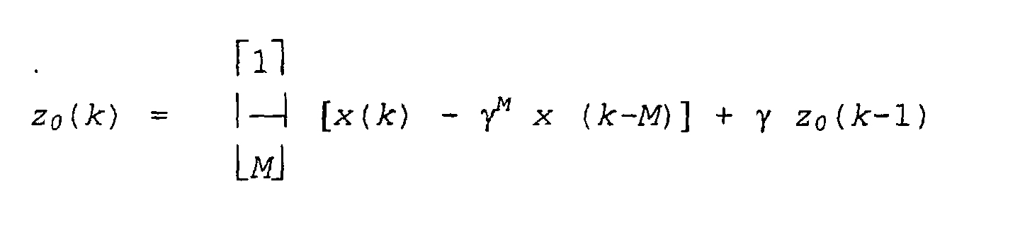
 für feste Filter m = 1, 2, ... M-1,
wobei γ ein Stabilitätsparameter ist, x(k) das rohe Eingangssignal für eine Abtastperiode k ist, M die Anzahl der festen Filter ist, und zm(k) das gefilterte Eingangssignal für den m-ten Filter ist, m = 0, 1 ... M-1. - Integriertes System zur Sprachverbesserung in einem Fahrzeug sowie Freisprech-Mobilfunksystem nach Anspruch 1, wobei das Rauschverminderungsfilter Folgendes umfaßt:mehrere feste Filter, wobei jeder feste Filter ein rohes Eingangssignal annimmt, das von zumindest einem der Mikrophonsignale des Systems stammt, und ein jeweiliges gefiltertes Signal ausgibt;ein jedem festen Filter entsprechendes zeitveränderliches Filterverstärkungselement, das das entsprechende gefilterte Signal annimmt und ein gewichtetes und gefiltertes Signal ausgibt, wobei jedes zeitveränderliche Filterverstärkungselement einen Wert aufweist, der sich im Zeitverlauf im Verhältnis zu einem Signalstärkepegel für das jeweilige gefilterte Signal verändert; undeine Summiervorrichtung, die die gewichteten und gefilterten Eingangssignale annimmt und ein rauschvermindertes Signal ausgibt.
- Integriertes System zur Sprachverbesserung in einem Fahrzeug sowie Freisprech-Mobilfunksystem nach Anspruch 9, wobei der Wert jedes zeitveränderlichen Filterverstärkungselements nach dem folgenden Ausdruck bestimmt wird:wobei βm(k) der Wert des zeitveränderlichen Filterverstärkungselements für den m-ten festen Filter bei der Abtastperiode k ist, m = 0, 1 ... M-1, SSLm(k) der Sprachstärkepegel für das jeweilige gefilterte Telefoneingangssignal bei der Abtastperiode k ist, und µ und α vorgewählte Leistungsparameter sind, die Werte von größer als 0 aufweisen.

- Integriertes System zur Sprachverbesserung in einem Fahrzeug sowie Freisprech-Mobilfunksystem nach Anspruch 10, wobei das zeitveränderliche Filterverstärkungselement βm(k) für den m-ten festen Filter gleich Null gesetzt wird, wenn die Rauschleistung für das jeweilige Frequenzband größer als ein vorgewählter Schwellenwert ist.
- Integriertes System zur Sprachverbesserung in einem Fahrzeug sowie Freisprech-Mobilfunksystem nach Anspruch 10 oder Anspruch 11, wobei der Leistungsparameter µ ungefähr gleich 4 ist, und der Leistungsparameter α ungefähr gleich 2 ist.
- Integriertes System zur Sprachverbesserung in einem Fahrzeug sowie Freisprech-Mobilfunksystem nach einem der Ansprüche 10 bis 12, wobei der Sprachstärkepegel für das jeweilige gefilterte Eingangssignal bei der Abtastperiode k nach dem folgenden Ausdruck bestimmt wird:
- Integriertes System zur Sprachverbesserung in einem Fahrzeug sowie Freisprech-Mobilfunksystem nach Anspruch 13, wobei die Rauschleistungspegelschätzung n_pwrm(k), m = 0, 1 ... M-1, für die Abtastperiode k für jedes der gefilterten Eingangssignale nach dem folgenden Ausdruck erreicht wird:
- Integriertes System zur Sprachverbesserung in einem Fahrzeug sowie Freisprech-Mobilfunksystem nach Anspruch 14, wobei die Zeitkonstante λ0 mit einem kleinen Wert festgesetzt wird, wodurch ein langes Mittelwertbildungsfenster zum Schätzen des Rauschleistungspegels bereitgestellt wird.
- Integriertes System zur Sprachverbesserung in einem Fahrzeug sowie Freisprech-Mobilfunksystem nach Anspruch 13, wobei der kombinierte Sprach- und Rauschleistungspegel s_pwrm(k), m = 0, 1 ... M-1, für die Abtastperiode k für jedes der gefilterten Eingangssignale nach dem folgenden Ausdruck geschätzt wird:
- Integriertes System zur Sprachverbesserung in einem Fahrzeug sowie Freisprech-Mobilfunksystem nach Anspruch 1, wobei das bestimmte primäre Mikrophon in einen "Ein"-Zustand gestellt wird und das eine oder die mehreren anderen Mikrophone in einen "Aus"-Zustand gestellt verbleiben, und das eine oder die mehreren Mikrophone im "Aus"-Zustand ungefähr 20 % ihrer jeweiligen Mikrophonsignale zum Telefoneingangssignal beitragen.
- Integriertes System zur Sprachverbesserung in einem Fahrzeug sowie Freisprech-Mobilfunksystem nach einem der vorhergehenden Ansprüche, wobei
das zellulare Telefon ein Telefonempfangssignal ausgibt, das sowohl mit dem nahen Eingangssignal als auch mit dem fernen Eingangssignal kombiniert ist. - Integriertes System zur Sprachverbesserung in einem Fahrzeug sowie Freisprech-Mobilfunksystem nach Anspruch 18, ferner umfassend
einen Mikrophonprivatbereichschalter, der die Übertragung des fernen Sprachsignals zum Mikrophonsteuerungsschalter unterbricht, wenn der Mikrophonprivatbereichschalter offen ist; und
einen Lautsprecherprivatbereichschalter, der die Übertragung des Telefonempfangssignals zur Kombination mit dem fernen Eingangssignal, welches der ferne Lautsprecher annimmt, unterbricht, wenn der Lautsprecherprivatbereichschalter offen ist. - Integriertes System zur Sprachverbesserung in einem Fahrzeug sowie Freisprech-Mobilfunksystem nach Anspruch 1, ferner umfassend
mehrere nahe Mikrophone, die jeweils Schall in der nahen Zone abfühlen und jeweils ein nahes Sprachsignal erzeugen;
mehrere ferne Mikrophone, die jeweils Schall in der fernen Zone abfühlen und jeweils ein fernes Sprachsignal erzeugen;
einen oder mehrere nahe adaptive Echounterdrückungskanäle, die jeweils ein jeweiliges nahes Eingangssignal erhalten und ein nahes Echounterdrückungssignal für ein zugehöriges nahes Mikrophon ausgeben;
eine nahe Echounterdrückungssummiervorrichtung für jedes nahe Mikrophon, die das jeweilige nahe Sprachsignal vom jeweiligen nahen Mikrophon und jegliches nahe Echounterdrückungssignal vom zugehörigen einen oder den zugehörigen mehreren nahen adaptiven Echounterdrückungskanälen annimmt und ein jeweiliges nahes Sprachsignal mit unterdrücktem Echo ausgibt;
einen oder mehrere ferne adaptive Echounterdrückungskanäle, die jeweils ein jeweiliges fernes Eingangssignal erhalten und ein fernes Echounterdrückungssignal für ein zugehöriges fernes Mikrophon ausgeben;
eine ferne Echounterdrückungssummiervorrichtung für jedes ferne Mikrophon, die das ferne Sprachsignal vom jeweiligen fernen Mikrophon und jegliches ferne Echounterdrückungssignal vom zugehörigen einen oder den zugehörigen mehreren fernen adaptiven Echounterdrückungskanälen annimmt und ein jeweiliges fernes Sprachsignal mit unterdrücktem Echo ausgibt; wobei
der Mikrophonsteuerungsschalter die nahen Sprachsignale mit unterdrücktem Echo und die fernen Sprachsignale mit unterdrücktem Echo annimmt und ein Telefoneingangssignal ausgibt. - System zur Sprachverbesserung, umfassend
eine nahe akustische Zone;
eine ferne akustische Zone;
mehrere nahe Mikrophone, die jeweils Schall in der nahen Zone abfühlen und jeweils ein nahes Sprachsignal erzeugen;
mehrere ferne Mikrophone, die jeweils Schall in der fernen Zone abfühlen und jeweils ein fernes Sprachsignal erzeugen;
zumindest einen nahen Lautsprecher, der ein nahes Eingangssignal annimmt und Schall in die nahe Zone ausgibt;
zumindest einen fernen Lautsprecher, der ein fernes Eingangssignal annimmt und Schall in die ferne Zone ausgibt;
einen oder mehrere nahe adaptive Echounterdrückungskanäle, die jeweils ein jeweiliges nahes Eingangssignal erhalten und ein nahes Echounterdrückungssignal für ein zugehöriges nahes Mikrophon ausgeben;
eine nahe Echounterdrückungssummiervorrichtung für jedes nahe Mikrophon, die das nahe Sprachsignal vom jeweiligen nahen Mikrophon und jegliches nahe Echounterdrückungssignal vom zugehörigen einen oder den zugehörigen mehreren nahen adaptiven Echounterdrückungskanälen annimmt und ein jeweiliges nahes Sprachsignal mit unterdrücktem Echo ausgibt;
einen oder mehrere ferne adaptive Echounterdrückungskanäle, die jeweils ein jeweiliges fernes Eingangssignal erhalten und ein fernes Echounterdrückungssignal für ein zugehöriges fernes Mikrophon ausgeben;
eine ferne Echounterdrückungssummiervorrichtung für jedes ferne Mikrophon, die das ferne Sprachsignal vom jeweiligen fernen Mikrophon und jegliches ferne Echounterdrückungssignal vom zugehörigen einen oder den zugehörigen mehreren fernen adaptiven Echounterdrückungskanälen annimmt und ein jeweiliges fernes Sprachsignal mit unterdrücktem Echo ausgibt;
ein Mittel zum Kombinieren der mehreren nahen Sprachsignale mit unterdrücktem Echo, um ein nahes Sprachverbesserungseingangssignal zu bilden, das eine Sprachkomponente des fernen Eingangssignals zum fernen Lautsprecher ist; und
ein Mittel zum Kombinieren der mehreren fernen Sprachsignale mit unterdrücktem Echo, um ein fernes Sprachverbesserungseingangssignal zu bilden, das eine Sprachkomponente des nahen Eingangssignals zum nahen Lautsprecher ist, wobei
das Mittel zum Kombinieren der mehreren nahen Sprachsignale mit unterdrücktem Echo ein Mittel zum Bestimmen eines der nahen Sprachsignale mit unterdrücktem Echo als ein primäres nahes Sprachsignal aufweist, und wobei das bestimmte primäre nahe Mikrophon in einen "Ein"-Zustand gestellt wird und das eine oder die mehreren anderen nahen Mikrophone in einen "Aus"-Zustand gestellt verbleiben, und das eine oder die mehreren nahen Mikrophone im "Aus"-Zustand weniger als 10 % ihrer jeweiligen Mikrophonsignale zum nahen Sprachverbesserungseingangssignal beitragen; und
das Mittel zum Kombinieren der mehreren fernen Sprachsignale mit unterdrücktem Echo ein Mittel zum Bestimmen eines der fernen Sprachsignale mit unterdrücktem Echo als ein primäres fernes Sprachsignal aufweist, und wobei das bestimmte primäre ferne Mikrophon in einen "Ein"-Zustand gestellt wird und das eine oder die mehreren anderen fernen Mikrophone in einen "Aus"-Zustand gestellt verbleiben, und das eine oder die mehreren fernen Mikrophone im "Aus"-Zustand weniger als 10 % ihrer jeweiligen Mikrophonsignale zum fernen Sprachverbesserungseingangssignal beitragen.
Applications Claiming Priority (2)
| Application Number | Priority Date | Filing Date | Title |
|---|---|---|---|
| US12529 | 1996-02-29 | ||
| US09/012,529 US6505057B1 (en) | 1998-01-23 | 1998-01-23 | Integrated vehicle voice enhancement system and hands-free cellular telephone system |
Publications (3)
| Publication Number | Publication Date |
|---|---|
| EP0932142A2 EP0932142A2 (de) | 1999-07-28 |
| EP0932142A3 EP0932142A3 (de) | 2000-03-15 |
| EP0932142B1 true EP0932142B1 (de) | 2005-07-20 |
Family
ID=21755393
Family Applications (1)
| Application Number | Title | Priority Date | Filing Date |
|---|---|---|---|
| EP99300462A Expired - Lifetime EP0932142B1 (de) | 1998-01-23 | 1999-01-22 | Integriertes System zur Sprachverbesserung in einem Fahrzeug sowie Freisprech-Mobilfunksystem |
Country Status (3)
| Country | Link |
|---|---|
| US (1) | US6505057B1 (de) |
| EP (1) | EP0932142B1 (de) |
| DE (1) | DE69926155T2 (de) |
Families Citing this family (73)
| Publication number | Priority date | Publication date | Assignee | Title |
|---|---|---|---|---|
| US7346374B2 (en) | 1999-05-26 | 2008-03-18 | Johnson Controls Technology Company | Wireless communications system and method |
| EP1246414B1 (de) | 1999-05-26 | 2012-05-23 | Johnson Controls Technology Company | Schnurlosses Kommunikationssystem und Verfahren dafür |
| US6744887B1 (en) * | 1999-10-05 | 2004-06-01 | Zhone Technologies, Inc. | Acoustic echo processing system |
| ATE248497T1 (de) * | 1999-12-09 | 2003-09-15 | Frederick Johannes Bruwer | Sprachsverteilungssystem |
| EP1143411A3 (de) | 2000-04-06 | 2004-11-03 | Siemens VDO Automotive Inc. | Stabilitätslösung für aktive Lärmdämpfung |
| EP1172258B1 (de) * | 2000-07-13 | 2004-09-29 | paragon AG | Freisprechanordnung |
| JP2004506944A (ja) * | 2000-08-15 | 2004-03-04 | コーニンクレッカ フィリップス エレクトロニクス エヌ ヴィ | 共通エコー相殺機能を備える複数装置型オーディオ/ビデオ |
| DE10202061A1 (de) | 2001-01-18 | 2002-09-19 | Andreas Peiker | Anordnung mit Mobiltelefon |
| US7248901B2 (en) | 2001-01-18 | 2007-07-24 | Andreas Peiker | Arrangement for handling a communication device |
| WO2002101728A1 (es) * | 2001-06-11 | 2002-12-19 | Lear Automotive (Eeds) Spain, S.L. | Metodo y sistema para cancelacion de exos y ruidos en entornos con condiciones acusticas variables y altamente realimentados |
| DE60208480T2 (de) * | 2001-10-05 | 2006-08-03 | Matsushita Electric Industrial Co., Ltd., Kadoma | Freisprecheinrichtung zur mobilen Kommunikation im Fahrzeug |
| US6993367B2 (en) * | 2002-09-04 | 2006-01-31 | Fujitsu Ten Limited | In-car telephone system, hands-free unit and portable telephone unit |
| US7103394B2 (en) * | 2003-01-28 | 2006-09-05 | Morphy William F | Motorcycle audio system control device and method |
| US20050221852A1 (en) * | 2004-04-05 | 2005-10-06 | D Avello Robert F | Methods for controlling processing of inputs to a vehicle wireless communication interface |
| EP1625973B1 (de) * | 2004-08-10 | 2007-08-01 | Volkswagen Aktiengesellschaft | Sprachunterstützungssystem für ein Kraftfahrzeug |
| US7716056B2 (en) * | 2004-09-27 | 2010-05-11 | Robert Bosch Corporation | Method and system for interactive conversational dialogue for cognitively overloaded device users |
| US7792314B2 (en) * | 2005-04-20 | 2010-09-07 | Mitsubishi Electric Research Laboratories, Inc. | System and method for acquiring acoustic signals using doppler techniques |
| ATE415048T1 (de) * | 2005-07-28 | 2008-12-15 | Harman Becker Automotive Sys | Verbesserte kommunikation für innenräume von kraftfahrzeugen |
| US7742790B2 (en) * | 2006-05-23 | 2010-06-22 | Alon Konchitsky | Environmental noise reduction and cancellation for a communication device including for a wireless and cellular telephone |
| WO2007145876A2 (en) * | 2006-06-02 | 2007-12-21 | Electro-Media Design, Ltd | Communication system, apparatus and method |
| US7908134B1 (en) * | 2006-07-26 | 2011-03-15 | Starmark, Inc. | Automatic volume control to compensate for speech interference noise |
| WO2009082378A2 (en) | 2006-10-11 | 2009-07-02 | Johnson Controls Technology Company | Wireless network selection |
| US8223981B2 (en) | 2008-05-23 | 2012-07-17 | Analog Devices, Inc. | Wide dynamic range microphone |
| US8041054B2 (en) | 2008-10-31 | 2011-10-18 | Continental Automotive Systems, Inc. | Systems and methods for selectively switching between multiple microphones |
| US9020158B2 (en) * | 2008-11-20 | 2015-04-28 | Harman International Industries, Incorporated | Quiet zone control system |
| US8135140B2 (en) * | 2008-11-20 | 2012-03-13 | Harman International Industries, Incorporated | System for active noise control with audio signal compensation |
| US8718289B2 (en) * | 2009-01-12 | 2014-05-06 | Harman International Industries, Incorporated | System for active noise control with parallel adaptive filter configuration |
| US8189799B2 (en) * | 2009-04-09 | 2012-05-29 | Harman International Industries, Incorporated | System for active noise control based on audio system output |
| US8199924B2 (en) * | 2009-04-17 | 2012-06-12 | Harman International Industries, Incorporated | System for active noise control with an infinite impulse response filter |
| US8077873B2 (en) * | 2009-05-14 | 2011-12-13 | Harman International Industries, Incorporated | System for active noise control with adaptive speaker selection |
| FR2945696B1 (fr) * | 2009-05-14 | 2012-02-24 | Parrot | Procede de selection d'un microphone parmi deux microphones ou plus, pour un systeme de traitement de la parole tel qu'un dispositif telephonique "mains libres" operant dans un environnement bruite. |
| CN102131014A (zh) * | 2010-01-13 | 2011-07-20 | 歌尔声学股份有限公司 | 时频域联合回声消除装置及方法 |
| US10115392B2 (en) * | 2010-06-03 | 2018-10-30 | Visteon Global Technologies, Inc. | Method for adjusting a voice recognition system comprising a speaker and a microphone, and voice recognition system |
| US20140274216A1 (en) * | 2013-03-15 | 2014-09-18 | Onbeond, Llc | Mobile communication device |
| US9484043B1 (en) * | 2014-03-05 | 2016-11-01 | QoSound, Inc. | Noise suppressor |
| US20160039356A1 (en) * | 2014-08-08 | 2016-02-11 | General Motors Llc | Establishing microphone zones in a vehicle |
| US9699550B2 (en) | 2014-11-12 | 2017-07-04 | Qualcomm Incorporated | Reduced microphone power-up latency |
| US9743213B2 (en) * | 2014-12-12 | 2017-08-22 | Qualcomm Incorporated | Enhanced auditory experience in shared acoustic space |
| US9672805B2 (en) | 2014-12-12 | 2017-06-06 | Qualcomm Incorporated | Feedback cancelation for enhanced conversational communications in shared acoustic space |
| US9565493B2 (en) | 2015-04-30 | 2017-02-07 | Shure Acquisition Holdings, Inc. | Array microphone system and method of assembling the same |
| US9554207B2 (en) | 2015-04-30 | 2017-01-24 | Shure Acquisition Holdings, Inc. | Offset cartridge microphones |
| DE102015010723B3 (de) * | 2015-08-17 | 2016-12-15 | Audi Ag | Selektive Schallsignalerfassung im Kraftfahrzeug |
| US10542154B2 (en) | 2015-10-16 | 2020-01-21 | Panasonic Intellectual Property Management Co., Ltd. | Device for assisting two-way conversation and method for assisting two-way conversation |
| EP3333850A4 (de) * | 2015-10-16 | 2018-06-27 | Panasonic Intellectual Property Management Co., Ltd. | Vorrichtung zur trennung von schallquellen und verfahren zur trennung von schallquellen |
| JP2017083600A (ja) | 2015-10-27 | 2017-05-18 | パナソニックIpマネジメント株式会社 | 車載収音装置及び収音方法 |
| US10839302B2 (en) | 2015-11-24 | 2020-11-17 | The Research Foundation For The State University Of New York | Approximate value iteration with complex returns by bounding |
| US10367948B2 (en) | 2017-01-13 | 2019-07-30 | Shure Acquisition Holdings, Inc. | Post-mixing acoustic echo cancellation systems and methods |
| US10049686B1 (en) | 2017-02-13 | 2018-08-14 | Bose Corporation | Audio systems and method for perturbing signal compensation |
| CN107135443B (zh) * | 2017-03-29 | 2020-06-23 | 联想(北京)有限公司 | 一种信号处理方法及电子设备 |
| CN112335261B (zh) | 2018-06-01 | 2023-07-18 | 舒尔获得控股公司 | 图案形成麦克风阵列 |
| US11297423B2 (en) | 2018-06-15 | 2022-04-05 | Shure Acquisition Holdings, Inc. | Endfire linear array microphone |
| US11310596B2 (en) | 2018-09-20 | 2022-04-19 | Shure Acquisition Holdings, Inc. | Adjustable lobe shape for array microphones |
| JP7217572B2 (ja) * | 2018-09-20 | 2023-02-03 | シグニファイ ホールディング ビー ヴィ | 分散マイクロホンシステムを構成するための方法及びコントローラ |
| EP3667662B1 (de) * | 2018-12-12 | 2022-08-10 | Panasonic Intellectual Property Corporation of America | Vorrichtung zur unterdrückung von akustischem echo, verfahren zur unterdrückung von akustischem echo und programm zur unterdrückung von akustischem echo |
| US11303981B2 (en) | 2019-03-21 | 2022-04-12 | Shure Acquisition Holdings, Inc. | Housings and associated design features for ceiling array microphones |
| JP7572964B2 (ja) | 2019-03-21 | 2024-10-24 | シュアー アクイジッション ホールディングス インコーポレイテッド | 阻止機能を伴うビーム形成マイクロフォンローブの自動集束、領域内自動集束、および自動配置 |
| US11558693B2 (en) | 2019-03-21 | 2023-01-17 | Shure Acquisition Holdings, Inc. | Auto focus, auto focus within regions, and auto placement of beamformed microphone lobes with inhibition and voice activity detection functionality |
| TW202101422A (zh) | 2019-05-23 | 2021-01-01 | 美商舒爾獲得控股公司 | 可操縱揚聲器陣列、系統及其方法 |
| WO2020243471A1 (en) | 2019-05-31 | 2020-12-03 | Shure Acquisition Holdings, Inc. | Low latency automixer integrated with voice and noise activity detection |
| CN114467312A (zh) | 2019-08-23 | 2022-05-10 | 舒尔获得控股公司 | 具有改进方向性的二维麦克风阵列 |
| US12028678B2 (en) | 2019-11-01 | 2024-07-02 | Shure Acquisition Holdings, Inc. | Proximity microphone |
| US11552611B2 (en) | 2020-02-07 | 2023-01-10 | Shure Acquisition Holdings, Inc. | System and method for automatic adjustment of reference gain |
| USD944776S1 (en) | 2020-05-05 | 2022-03-01 | Shure Acquisition Holdings, Inc. | Audio device |
| US11706562B2 (en) | 2020-05-29 | 2023-07-18 | Shure Acquisition Holdings, Inc. | Transducer steering and configuration systems and methods using a local positioning system |
| CN112530453B (zh) * | 2020-11-27 | 2022-04-05 | 五邑大学 | 一种适用于噪声环境下的语音识别方法及装置 |
| JP7814400B2 (ja) | 2021-01-28 | 2026-02-16 | シュアー アクイジッション ホールディングス インコーポレイテッド | ハイブリッドオーディオビーム形成システム |
| US12452584B2 (en) | 2021-01-29 | 2025-10-21 | Shure Acquisition Holdings, Inc. | Scalable conferencing systems and methods |
| DE102021115652A1 (de) | 2021-06-17 | 2022-12-22 | Audi Aktiengesellschaft | Verfahren zum Ausblenden von mindestens einem Geräusch |
| US12542123B2 (en) | 2021-08-31 | 2026-02-03 | Shure Acquisition Holdings, Inc. | Mask non-linear processor for acoustic echo cancellation |
| US12289584B2 (en) | 2021-10-04 | 2025-04-29 | Shure Acquisition Holdings, Inc. | Networked automixer systems and methods |
| EP4427465A1 (de) | 2021-11-05 | 2024-09-11 | Shure Acquisition Holdings, Inc. | Verteilter algorithmus zur automatischen mischung von sprache über drahtlose netzwerke |
| US12250526B2 (en) | 2022-01-07 | 2025-03-11 | Shure Acquisition Holdings, Inc. | Audio beamforming with nulling control system and methods |
| US12598261B2 (en) | 2022-09-28 | 2026-04-07 | Shure Acquisition Holdings, Inc. | Wideband doubletalk detection for optimization of acoustic echo cancellation |
Family Cites Families (25)
| Publication number | Priority date | Publication date | Assignee | Title |
|---|---|---|---|---|
| US4025721A (en) | 1976-05-04 | 1977-05-24 | Biocommunications Research Corporation | Method of and means for adaptively filtering near-stationary noise from speech |
| US4630305A (en) | 1985-07-01 | 1986-12-16 | Motorola, Inc. | Automatic gain selector for a noise suppression system |
| WO1987001546A1 (en) | 1985-09-03 | 1987-03-12 | Motorola, Inc. | Hands-free control system for a radiotelephone |
| JPH0344222A (ja) * | 1989-07-12 | 1991-02-26 | Toshiba Corp | 無線電話装置 |
| US5259035A (en) | 1991-08-02 | 1993-11-02 | Knowles Electronics, Inc. | Automatic microphone mixer |
| JPH05111020A (ja) * | 1991-10-17 | 1993-04-30 | Matsushita Electric Ind Co Ltd | テレビ会議用画面切替制御装置 |
| JP2921232B2 (ja) * | 1991-12-27 | 1999-07-19 | 日産自動車株式会社 | 能動型不快波制御装置 |
| JP2792311B2 (ja) * | 1992-01-31 | 1998-09-03 | 日本電気株式会社 | 多チャンネルエコー除去方法および装置 |
| JP2508574B2 (ja) * | 1992-11-10 | 1996-06-19 | 日本電気株式会社 | 多チャンネルエコ―除去装置 |
| US5432859A (en) | 1993-02-23 | 1995-07-11 | Novatel Communications Ltd. | Noise-reduction system |
| EP0707763B1 (de) | 1993-07-07 | 2001-08-29 | Picturetel Corporation | Verringerung des hintergrundrauschens zur sprachverbesserung |
| US5764779A (en) | 1993-08-25 | 1998-06-09 | Canon Kabushiki Kaisha | Method and apparatus for determining the direction of a sound source |
| US5526419A (en) | 1993-12-29 | 1996-06-11 | At&T Corp. | Background noise compensation in a telephone set |
| US5574824A (en) | 1994-04-11 | 1996-11-12 | The United States Of America As Represented By The Secretary Of The Air Force | Analysis/synthesis-based microphone array speech enhancer with variable signal distortion |
| US5664019A (en) * | 1995-02-08 | 1997-09-02 | Interval Research Corporation | Systems for feedback cancellation in an audio interface garment |
| US5680450A (en) * | 1995-02-24 | 1997-10-21 | Ericsson Inc. | Apparatus and method for canceling acoustic echoes including non-linear distortions in loudspeaker telephones |
| DE69634027T2 (de) | 1995-08-14 | 2005-12-22 | Nippon Telegraph And Telephone Corp. | Akustischer Teilband-Echokompensator |
| FI111896B (fi) * | 1995-11-24 | 2003-09-30 | Nokia Corp | Kaksitoimisen tiedonvälityslaitteen käyttöä helpottava toiminto ja kaksitoiminen tiedonvälityslaite |
| DE69731573T2 (de) | 1996-02-09 | 2005-03-31 | Texas Instruments Inc., Dallas | Geräuschverminderungsanordnung |
| US5903819A (en) | 1996-03-13 | 1999-05-11 | Ericsson Inc. | Noise suppressor circuit and associated method for suppressing periodic interference component portions of a communication signal |
| US5706344A (en) | 1996-03-29 | 1998-01-06 | Digisonix, Inc. | Acoustic echo cancellation in an integrated audio and telecommunication system |
| KR0180896B1 (ko) * | 1996-07-19 | 1999-05-15 | 정인현 | 개인휴대용 통신 단말기용 자동차 내장장치 |
| US5796819A (en) * | 1996-07-24 | 1998-08-18 | Ericsson Inc. | Echo canceller for non-linear circuits |
| US5978689A (en) * | 1997-07-09 | 1999-11-02 | Tuoriniemi; Veijo M. | Personal portable communication and audio system |
| US6131042A (en) * | 1998-05-04 | 2000-10-10 | Lee; Chang | Combination cellular telephone radio receiver and recorder mechanism for vehicles |
-
1998
- 1998-01-23 US US09/012,529 patent/US6505057B1/en not_active Expired - Lifetime
-
1999
- 1999-01-22 DE DE69926155T patent/DE69926155T2/de not_active Expired - Lifetime
- 1999-01-22 EP EP99300462A patent/EP0932142B1/de not_active Expired - Lifetime
Also Published As
| Publication number | Publication date |
|---|---|
| US6505057B1 (en) | 2003-01-07 |
| EP0932142A2 (de) | 1999-07-28 |
| EP0932142A3 (de) | 2000-03-15 |
| DE69926155T2 (de) | 2006-04-20 |
| DE69926155D1 (de) | 2005-08-25 |
Similar Documents
| Publication | Publication Date | Title |
|---|---|---|
| EP0932142B1 (de) | Integriertes System zur Sprachverbesserung in einem Fahrzeug sowie Freisprech-Mobilfunksystem | |
| EP0843934B1 (de) | Einrichtung zur unterdrückung einer störenden komponente eines eingangssignals | |
| EP1429315B1 (de) | Verfahren und system zum unterdrücken von echos und geräuschen in umgebungen unter variablen akustischen und stark rückgekoppelten bedingungen | |
| EP1298815B1 (de) | Echoprozessor mit einem Pseudo-Hintergrundrauschengenerator | |
| US6674865B1 (en) | Automatic volume control for communication system | |
| US7171003B1 (en) | Robust and reliable acoustic echo and noise cancellation system for cabin communication | |
| EP1855457B1 (de) | Kompensation von Mehrkanalechos durch Dekorrelation | |
| DE69331223T2 (de) | Netzwerkechokompensator | |
| US7117145B1 (en) | Adaptive filter for speech enhancement in a noisy environment | |
| US7003099B1 (en) | Small array microphone for acoustic echo cancellation and noise suppression | |
| US7062040B2 (en) | Suppression of echo signals and the like | |
| JP2538176B2 (ja) | エコ―制御装置 | |
| US8306215B2 (en) | Echo canceller for eliminating echo without being affected by noise | |
| US5933495A (en) | Subband acoustic noise suppression | |
| EP1097562B1 (de) | Adaptiver filter und akustischer echokompensator mit demselben | |
| US7039197B1 (en) | User interface for communication system | |
| US7054437B2 (en) | Statistical adaptive-filter controller | |
| US20040264610A1 (en) | Interference cancelling method and system for multisensor antenna | |
| EP0895397A2 (de) | Akusticher Echokompensator | |
| US20030026442A1 (en) | Subband acoustic feedback cancellation in hearing aids | |
| EP1022866A1 (de) | Echounterdrückungsverfahren, echokompensator und sprachschalter | |
| KR20040019362A (ko) | 후처리기로서 멀티 마이크로폰 에코 억제기를 가지는 음향보강 시스템 | |
| EP0789476B1 (de) | Geräuschverminderungsanordnung | |
| KR20040019339A (ko) | 반향 억제기 및 확성기 빔 형성기를 구비한 사운드 보강시스템 | |
| Martin et al. | Coupled adaptive filters for acoustic echo control and noise reduction |
Legal Events
| Date | Code | Title | Description |
|---|---|---|---|
| PUAI | Public reference made under article 153(3) epc to a published international application that has entered the european phase |
Free format text: ORIGINAL CODE: 0009012 |
|
| AK | Designated contracting states |
Kind code of ref document: A2 Designated state(s): DE FR GB |
|
| AX | Request for extension of the european patent |
Free format text: AL;LT;LV;MK;RO;SI |
|
| PUAL | Search report despatched |
Free format text: ORIGINAL CODE: 0009013 |
|
| AK | Designated contracting states |
Kind code of ref document: A3 Designated state(s): AT BE CH CY DE DK ES FI FR GB GR IE IT LI LU MC NL PT SE |
|
| AX | Request for extension of the european patent |
Free format text: AL;LT;LV;MK;RO;SI |
|
| 17P | Request for examination filed |
Effective date: 20000912 |
|
| AKX | Designation fees paid |
Free format text: DE FR GB |
|
| 17Q | First examination report despatched |
Effective date: 20040720 |
|
| GRAP | Despatch of communication of intention to grant a patent |
Free format text: ORIGINAL CODE: EPIDOSNIGR1 |
|
| RIC1 | Information provided on ipc code assigned before grant |
Ipc: 7G 10L 21/02 A |
|
| GRAS | Grant fee paid |
Free format text: ORIGINAL CODE: EPIDOSNIGR3 |
|
| GRAA | (expected) grant |
Free format text: ORIGINAL CODE: 0009210 |
|
| AK | Designated contracting states |
Kind code of ref document: B1 Designated state(s): DE FR GB |
|
| REG | Reference to a national code |
Ref country code: GB Ref legal event code: FG4D |
|
| REF | Corresponds to: |
Ref document number: 69926155 Country of ref document: DE Date of ref document: 20050825 Kind code of ref document: P |
|
| PG25 | Lapsed in a contracting state [announced via postgrant information from national office to epo] |
Ref country code: GB Free format text: LAPSE BECAUSE OF NON-PAYMENT OF DUE FEES Effective date: 20060122 |
|
| PLBE | No opposition filed within time limit |
Free format text: ORIGINAL CODE: 0009261 |
|
| STAA | Information on the status of an ep patent application or granted ep patent |
Free format text: STATUS: NO OPPOSITION FILED WITHIN TIME LIMIT |
|
| 26N | No opposition filed |
Effective date: 20060421 |
|
| EN | Fr: translation not filed | ||
| PG25 | Lapsed in a contracting state [announced via postgrant information from national office to epo] |
Ref country code: FR Free format text: LAPSE BECAUSE OF FAILURE TO SUBMIT A TRANSLATION OF THE DESCRIPTION OR TO PAY THE FEE WITHIN THE PRESCRIBED TIME-LIMIT Effective date: 20060915 |
|
| GBPC | Gb: european patent ceased through non-payment of renewal fee |
Effective date: 20060122 |
|
| PG25 | Lapsed in a contracting state [announced via postgrant information from national office to epo] |
Ref country code: FR Free format text: LAPSE BECAUSE OF FAILURE TO SUBMIT A TRANSLATION OF THE DESCRIPTION OR TO PAY THE FEE WITHIN THE PRESCRIBED TIME-LIMIT Effective date: 20050720 |
|
| PGFP | Annual fee paid to national office [announced via postgrant information from national office to epo] |
Ref country code: DE Payment date: 20180129 Year of fee payment: 20 |
|
| REG | Reference to a national code |
Ref country code: DE Ref legal event code: R071 Ref document number: 69926155 Country of ref document: DE |