EP0895397A2 - Akusticher Echokompensator - Google Patents
Akusticher Echokompensator Download PDFInfo
- Publication number
- EP0895397A2 EP0895397A2 EP98306066A EP98306066A EP0895397A2 EP 0895397 A2 EP0895397 A2 EP 0895397A2 EP 98306066 A EP98306066 A EP 98306066A EP 98306066 A EP98306066 A EP 98306066A EP 0895397 A2 EP0895397 A2 EP 0895397A2
- Authority
- EP
- European Patent Office
- Prior art keywords
- speaker
- echo
- echo canceller
- estimating
- signal
- Prior art date
- Legal status (The legal status is an assumption and is not a legal conclusion. Google has not performed a legal analysis and makes no representation as to the accuracy of the status listed.)
- Granted
Links
Images


Classifications
-
- H—ELECTRICITY
- H04—ELECTRIC COMMUNICATION TECHNIQUE
- H04M—TELEPHONIC COMMUNICATION
- H04M9/00—Arrangements for interconnection not involving centralised switching
- H04M9/08—Two-way loud-speaking telephone systems with means for conditioning the signal, e.g. for suppressing echoes for one or both directions of traffic
- H04M9/082—Two-way loud-speaking telephone systems with means for conditioning the signal, e.g. for suppressing echoes for one or both directions of traffic using echo cancellers
Definitions
- the present invention relates generally to the field of acoustic echo cancellation in telecommunications, and particularly to a pseudo spectrum-based acoustic echo canceller which adaptively cancels echoes arising in hands-free audio and video teleconferencing and related systems without requiring a state machine or training.
- a typical acoustic echo canceller currently available uses what-is-known-as an adaptive filter which employs a well-known algorithm such as the algorithm known as the Least-Mean-Square algorithm, or LMS.
- LMS Least-Mean-Square algorithm
- This algorithm continuously adapts to changes In the placement of both the speaker and microphone and to changes in loudspeaker volume.
- a state machine is needed to automatically determine each of the four states, i.e., receiving, transmitting, double-talk, and idle.
- these cancellers much be trained, that is, they must "leam" the loudspeaker-to-microphone acoustic response function for the room it is servicing.
- the acoustic compensation length is determined by the length of the filter that is determined by the host resource availability.
- a microphone array is used together with a block adaptive algorithm to effectively suppress acoustic echo arising in hands free voice communication.
- the system is also capable of suppressing environmental noise.
- the present echo canceller utilizes the principle that the spectrum pattem of human speech does not change much in the short run.
- the present echo canceller takes 256 overlap 128 samples in 16 ms intervals, or sample blocks.
- the power spectrum taken at time 0 and at any time within the 16 ms interval are generally the same. This is true even though the waveform of the speech may change over time even in the short run.
- the echoes are simply a delayed form of a speech signal. Therefore, in following the principle described above, the spectrum of the speech signal and the spectrum of the echo taking are substantially the same.
- the inputs to the present echo canceller are x ( t ) and y ( t ), y ( t ) representing the incoming speech signal from a far-end speaker and x ( t ) representing the combination of speech signal from a near-end speaker and the echo.
- the well-known normalized cross-correlation estimation between x ( t ) and y ( t ) is performed to determine the level of correlation between x ( t ) and y ( t ) which is quantitatively represented by the correlation coefficient C , a value of 1 for C being perfect correlation.
- x ( t ) comprises of only the echo portion which is essentially a delayed form of y ( t ). In that case, there is almost a perfect correlation between x ( t ) and y ( t ) and the C value is near 1.
- the x ( t ) comprises only of the signal and the C value is near 0.
- the C value may be between 0 and 1, but typically near to 0 since the two speech signals will not be highly correlated. And of course, silence would result in a near 0 also, since respective noises will not be highly correlated. Certain decisions are based on whether the C value exceeds certain thresholds.
- the amount of delay is estimated by measuring the time shift required to produce the maximum C value. Once the delay is determined, the two channels of inputs are aligned by time-shifting x ( t ) to match y ( t ). The amplitude of the x ( t ) and y ( t ) is then normalized by first determining a certain gain factor, and then multiplying y ( t ) by the gain factor.
- the processed forms of the input x ( t ) and y ( t ) are next processed by applying the well-known Hanning window. They are then transformed into their respective frequency domain using the well-known fast Fourier transform (FFT) and then to Bark Scales, P x ( b ) and P y ( b ) , using the Bark Frequency Warping technique.
- the transfer function H ( b ) is then estimated using the Bark Scales.
- the transfer function is used to normalize P y ( b ), which, in tum together with P x ( b ), is used to estimate the gain G ( b ) which will be used to suppress the echo.
- the Bark Scales are unwarped and the gain function is then used to suppress the echo from the input x ( t ).
- the well-known inverse FFT (IFFT) and overlap add are performed to yield an echo-free signal.
- FIG. 1 is a functional diagram illustrating the present echo canceller deployed in a teleconference room setting.
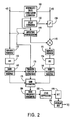
- FIG. 2 is functional block diagram illustrating the circuitry of the present echo canceller.
- FIGS. 3a through 3c is a continuous flow diagram illustrating the echo canceling process employed by the present echo canceller.
- FIG. 4 is a lookup Table 1 listing values for G s .
- FIG. 5 is a lookup Table 2 listing values for L b ( b ).
- FIG. 6 is a lookup Table 3 listing values for W i .
- FIG. 1 illustrates schematically the present echo canceller 1 placed in a telephone conference system operating in a room 10.
- the echo canceller 1 is serially connected to a telecommunications network through incoming line 15 and outgoing line 16.
- Room reverberative surfaces 18 define multiple echo paths which depend on room geometry. Two such echo paths, 20 and 21, are illustrated. Speech originating from a far-end speaker (speaker not shown) emanating from the room loudspeaker 1 travels along the echo paths 20 and 21, among others paths, and enters microphone 25 with various time delays. Speech 31 from the near-end speaker 30 also enters the microphone 25.
- Both the speech signal and the echo denoted as x ( t ), travel along the line 35 and into the echo canceller 1.
- the speech signal from the far-end speaker denoted as y ( t ), which is generally the same as the echo without the delay, is also an input to the echo canceller 1 via line 15.
- a microphone array consisting of 3 microphones is used instead of a single microphone, and a well-known beam-forming technique is employed. This arrangement enhances the strength of the near-end speech signal while reducing the strength of the echo signal from the loudspeaker. This occurs because the array forms an acoustic beam at the signal direction and a null in the speaker direction. It has been found that this microphone array significantly enhances the performance of embodiments of the present invention.
- the present echo canceller utilizes the principle that the spectrum pattern of human speech does not change much in the short run.
- the present echo canceller takes 256 overlap 128 samples in 16 ms intervals, or sample blocks.
- the power spectrum of a speech signal taken at time 0, for instance, and at any time within the 16 ms interval are generally the same. This is true even though the waveform of the speech may change over time even in the short run.
- the echo taking the paths 21 and 20, for instance are simply a delayed form of y ( t ). Therefore, in following the principle described above, the spectrum of the speech signal from the far-end speaker's speech signal y ( t ) and the spectrum of the echo taking the paths 21 and 20 are substantially the same. The following description will make it clearer to the those skilled in the art, how this principle is utilized in the present echo canceller to cancel the echo in a manner which is more effective than the currently-available systems.
- FIG. 2 illustrates a functional block diagram representing the circuitry for the echo canceller 1 referred to in FIG. 1.
- the circuitry would be implemented in a DSP chip or a microprocessor, though it can be implemented in other ways which are known to one skilled in the art.
- a brief description of the blocks will be given for FIG. 2.
- a more detailed flow diagram and description for the echo cancellation process employed by the circuit of FIG. 2 shall follow thereafter.
- the inputs to the circuit are x ( t ) and y ( t ), y ( t ) representing the incoming speech signal from the far-end speaker and x ( t ) representing the combination of speech signal from the near-end speaker and the echo.
- the well-known normalized cross-correlation estimation between x ( t ) and y ( t ) is performed in block 100 to determine the level of correlation between x ( t ) and y ( t ) which is quantitatively represented by the correlation coefficient C , a value of 1 for C being perfect correlation.
- x ( t ) comprises of only the echo portion which is generally a delayed form of y ( t ). In that case, there is almost a perfect correlation between x ( t ) and y ( t ) and the C value is near 1.
- the x ( t ) comprises only of the signal and the C value is near 0.
- the C value may be between 0 and 1, but typically near to 0 since the two speech signals will not be highly correlated. And of course, silence would result in a near 0 also, since respective noises will not be highly correlated. Certain decisions are based on whether the C value exceeds certain thresholds.
- the amount of delay is estimated in block 120 by measuring the time shift required to produce the maximum C value. Once the delay is determined, the two channels of inputs are aligned in block 130 by time-shifting y ( t ) to match x ( t ). The amplitude of the x ( t ) and y ( t ) is then normalized in block 140 by first determining a certain gain factor, and then multiplying y(t) by the gain factor in block 145.
- the processed form of the input x ( t ) is next processed in blocks 150 through 165; the processed form of the input y ( t ) is next processed 151 through 166. Because both channels are processed in an identical manner which is well known and understood, only a brief description will be provided.
- the well-known Hanning window is applied to the processed inputs. They are then transformed into their respective frequency domain using the well-known fast Fourier transform (FFT), blocks 155 and 156, and then to Bark Scales, P x ( b ) and P y ( b ), using the Bark Frequency Warping technique in blocks 165 and 166.
- FFT fast Fourier transform
- P x ( b ) and P y ( b ) using the Bark Frequency Warping technique in blocks 165 and 166.
- the transfer function H ( b ) is estimated.
- the transfer function is then used in block 175 to normalize P y ( b ), which is then used to estimate the gain G ( b ) which will be used to suppress the echo.
- the Bark Scales are unwarped.
- the gain function is then used to suppress the echo from the input spectrum in block 185.
- the well-known inverse FFT (IFFT) is performed in block 190 and the overlap add in block 195 to yield an echo-free signal.
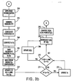
- M samples (in this case 256 overlap 128, though other values are possible) are taken from the inputs x ( t ) and y ( t ) in step 205 at 16 ms block intervals (8 KHz sampling rate).
- step 210 Sometimes a dc component exists with the inputs and so it is removed, step 210, using a common procedure well known to those skilled in the art.
- T denotes the transpose of a vector.
- a number of C values will result from this calculation so in step 220, the maximum value representing C , or C max , is chosen.
- step 230 the amount of delay between the two inputs, or D n , is estimated in step 230.
- the present canceller can still function, though not as optimally, even if steps 232, 234, 236, and 240 were eliminated, and step 245 were to be performed immediately after 230 using the same D n each time.
- step 250 an amplitude normalization is performed on the inputs using a gain normalization factor, Z which is initially set at 1, but which is continually updated in step 269 when the stated condition is met.
- ⁇ is near to 0, that indicates either a double-talk or only near-end speech or only silence.
- the coherence factor, ⁇ is used together with a non-linear energy function described in step 267 (see below) to further control the echo suppression.
- step 265 P x and P y are converted to Bark Scales P x ( b ) and P y ( b )using the well-known Bark Frequency Warping technique.
- the gain normalization factor, Z is updated if the following conditions are met: ⁇ > ⁇ and E n >T n .
- the gain normalization factor, Z is computed as follows: where ⁇ 1. It is important to note that while this is the preferred method other gain normalization methods may be used.
- step 275 it is determined whether ⁇ > ⁇ and E n > T n .
- ⁇ 0.65, though a different value may be optimal for ⁇ under different configuration, e.g., different microphone set-up. If the condition in step 275 is met, the transfer function H ( b ) is updated from its initial value of 1 in step 280. If the condition in step 275 is not met, then the step 285 is performed without updating the H ( b ).
- P y ( b ) is normalised by H ( b ) as follows:
- a buffer is provided to store M old values of ( b ).
- the total echo power is computed as follows: W i is a weighting fraction and its value depends on the echo path characteristics. The typical values are listed in Table 3.
- the value of G s is found by referring to lookup Table 1 using the current value for ⁇ .
- step 335 the G ( b ) is unwarped to produce G ( f ).
- the output spectrum is then computed in step 340 as follows:
- step 345 the well-known inverse FFT (IFFT) and overlap add are performed on ( f ) and to produce an echo-free signal ( t ).
- IFFT inverse FFT
- the cross-correlation estimation technique employed here may be substituted with other techniques for determining the correction between two signals.
- the amplitude normalisation, the use of Hanning Window and Bark Scales while contributing to the effectiveness of the preferred embodiment of the present invention, may be eliminated under some circumstances without completely negating the function of the present invention.
- the Bark Scales for instance, are used in this case as way of reducing computation time and, therefore, may not unduly effect the performance of the present echo canceller.
- the Hanning Window was found to be optimal in this case, it may be replaced with other windows.
Landscapes
- Engineering & Computer Science (AREA)
- Signal Processing (AREA)
- Cable Transmission Systems, Equalization Of Radio And Reduction Of Echo (AREA)
Applications Claiming Priority (2)
| Application Number | Priority Date | Filing Date | Title |
|---|---|---|---|
| SG9702744 | 1997-08-01 | ||
| SG1997002744A SG71035A1 (en) | 1997-08-01 | 1997-08-01 | Acoustic echo canceller |
Publications (4)
| Publication Number | Publication Date |
|---|---|
| EP0895397A2 true EP0895397A2 (de) | 1999-02-03 |
| EP0895397A3 EP0895397A3 (de) | 1999-08-18 |
| EP0895397B1 EP0895397B1 (de) | 2006-08-23 |
| EP0895397B9 EP0895397B9 (de) | 2007-01-17 |
Family
ID=20429709
Family Applications (1)
| Application Number | Title | Priority Date | Filing Date |
|---|---|---|---|
| EP98306066A Expired - Lifetime EP0895397B9 (de) | 1997-08-01 | 1998-07-30 | Akustischer Echokompensator |
Country Status (4)
| Country | Link |
|---|---|
| US (1) | US6249581B1 (de) |
| EP (1) | EP0895397B9 (de) |
| DE (1) | DE69835644T2 (de) |
| SG (1) | SG71035A1 (de) |
Cited By (10)
| Publication number | Priority date | Publication date | Assignee | Title |
|---|---|---|---|---|
| FR2802367A1 (fr) * | 1999-12-14 | 2001-06-15 | France Telecom | Procede temps reel de traitement et de gestion pour l'annulation d'echo entre haut-parleur et microphone d'un terminal informatique |
| WO2001045291A1 (en) | 1999-12-17 | 2001-06-21 | Nokia Corporation | A delay measurement system in a packet network |
| WO2002003563A1 (en) * | 2000-06-29 | 2002-01-10 | Ericsson Inc. | Echo suppression using adaptive gain based on residual echo energy |
| WO2003010996A3 (en) * | 2001-07-20 | 2003-05-30 | Koninkl Philips Electronics Nv | Sound reinforcement system having an echo suppressor and loudspeaker beamformer |
| WO2003010995A3 (en) * | 2001-07-20 | 2003-06-05 | Koninkl Philips Electronics Nv | Sound reinforcement system having an multi microphone echo suppressor as post processor |
| DE10043064B4 (de) * | 2000-09-01 | 2004-07-08 | Dietmar Dr. Ruwisch | Verfahren und Vorrichtung zur Elimination von Lautsprecherinterferenzen aus Mikrofonsignalen |
| WO2006111370A1 (en) * | 2005-04-19 | 2006-10-26 | Epfl (Ecole Polytechnique Federale De Lausanne) | A method and device for removing echo in a multi-channel audio signal |
| WO2009092522A1 (en) * | 2008-01-25 | 2009-07-30 | Fraunhofer-Gesellschaft zur Förderung der angewandten Forschung e.V. | Apparatus and method for computing control information for an echo suppression filter and apparatus and method for computing a delay value |
| WO2012158163A1 (en) * | 2011-05-17 | 2012-11-22 | Google Inc. | Non-linear post-processing for acoustic echo cancellation |
| US8743939B2 (en) * | 2002-07-03 | 2014-06-03 | Marvell International Ltd. | Nonlinear echo compensator for class B transmitter line driver |
Families Citing this family (25)
| Publication number | Priority date | Publication date | Assignee | Title |
|---|---|---|---|---|
| DE19850272A1 (de) * | 1998-10-31 | 2000-05-04 | Alcatel Sa | Verfahren zur Verbesserung der Echounterdrückung in einem Telekommunikaionssystem |
| US6766019B1 (en) * | 2000-07-21 | 2004-07-20 | Agere Systems Inc. | Method and apparatus for performing double-talk detection in acoustic echo cancellation |
| EP1372516B1 (de) | 2001-02-27 | 2009-05-13 | Smith & Nephew, Inc. | Chirurgisches navigationssystem zur teilweisen kniegelenkrekonstruktion |
| US7547307B2 (en) * | 2001-02-27 | 2009-06-16 | Smith & Nephew, Inc. | Computer assisted knee arthroplasty instrumentation, systems, and processes |
| US6889066B2 (en) * | 2001-03-27 | 2005-05-03 | Qualcomm Incorporated | Network echo suppression in mobile stations |
| JP2005516724A (ja) | 2002-02-11 | 2005-06-09 | スミス アンド ネフュー インコーポレーテッド | 画像案内式骨折整復 |
| US7272224B1 (en) * | 2003-03-03 | 2007-09-18 | Apple Inc. | Echo cancellation |
| US7363334B2 (en) * | 2003-08-28 | 2008-04-22 | Accoutic Processing Technology, Inc. | Digital signal-processing structure and methodology featuring engine-instantiated, wave-digital-filter componentry, and fabrication thereof |
| US20050065778A1 (en) * | 2003-09-24 | 2005-03-24 | Mastrianni Steven J. | Secure speech |
| US7862570B2 (en) | 2003-10-03 | 2011-01-04 | Smith & Nephew, Inc. | Surgical positioners |
| US7764985B2 (en) | 2003-10-20 | 2010-07-27 | Smith & Nephew, Inc. | Surgical navigation system component fault interfaces and related processes |
| US7794467B2 (en) | 2003-11-14 | 2010-09-14 | Smith & Nephew, Inc. | Adjustable surgical cutting systems |
| EP1729665A1 (de) | 2004-03-31 | 2006-12-13 | Smith and Nephew, Inc. | Verfahren und geräte zur bereitstellung einer referenz-array-eingabevorrichtung |
| EP1737375B1 (de) | 2004-04-21 | 2021-08-11 | Smith & Nephew, Inc | Computerunterstützte navigationssysteme für die schulter-arthroplastie |
| US7395790B2 (en) * | 2004-11-18 | 2008-07-08 | S&S Cycle, Inc. | Reed valve breather for evolution engine |
| US8177788B2 (en) | 2005-02-22 | 2012-05-15 | Smith & Nephew, Inc. | In-line milling system |
| US7647077B2 (en) | 2005-05-31 | 2010-01-12 | Bitwave Pte Ltd | Method for echo control of a wireless headset |
| US7856098B1 (en) * | 2005-09-15 | 2010-12-21 | Mindspeed Technologies, Inc. | Echo cancellation and control in discrete cosine transform domain |
| NO332437B1 (no) * | 2010-01-18 | 2012-09-17 | Cisco Systems Int Sarl | Apparat og fremgangsmate for a supprimere et akustisk ekko |
| US9065895B2 (en) * | 2012-02-22 | 2015-06-23 | Broadcom Corporation | Non-linear echo cancellation |
| US9628141B2 (en) * | 2012-10-23 | 2017-04-18 | Interactive Intelligence Group, Inc. | System and method for acoustic echo cancellation |
| US9083782B2 (en) * | 2013-05-08 | 2015-07-14 | Blackberry Limited | Dual beamform audio echo reduction |
| CN103414453B (zh) * | 2013-08-19 | 2016-02-24 | 北京无线电计量测试研究所 | 一种频率源短稳参数数字化检测方法及装置 |
| CN109448748B (zh) * | 2018-12-17 | 2021-08-03 | 嘉楠明芯(北京)科技有限公司 | 一种用于回声消除的滤波方法及装置、设备、介质 |
| CN111917926B (zh) * | 2019-05-09 | 2021-08-06 | 上海触乐信息科技有限公司 | 一种通信终端中的回声消除方法、装置及终端设备 |
Family Cites Families (12)
| Publication number | Priority date | Publication date | Assignee | Title |
|---|---|---|---|---|
| US3699271A (en) * | 1970-11-16 | 1972-10-17 | Bell Telephone Labor Inc | Speech processor using multiband controlled center clipping |
| US3784747A (en) * | 1971-12-03 | 1974-01-08 | Bell Telephone Labor Inc | Speech suppression by predictive filtering |
| DE3118473C2 (de) * | 1981-05-09 | 1987-02-05 | Felten & Guilleaume Fernmeldeanlagen GmbH, 8500 Nürnberg | Verfahren zur Aufbereitung elektrischer Signale mit einer digitalen Filteranordnung |
| US4644108A (en) * | 1982-10-27 | 1987-02-17 | International Business Machines Corporation | Adaptive sub-band echo suppressor |
| US4562312A (en) * | 1983-02-17 | 1985-12-31 | At&T Bell Laboratories | Subsampling delay estimator for an echo canceler |
| CA1332187C (en) * | 1986-10-30 | 1994-09-27 | Fumio Amano | Echo canceller with short processing delay and decreased multiplication number |
| NL8701633A (nl) * | 1987-07-10 | 1989-02-01 | Philips Nv | Digitale echocompensator. |
| US5588089A (en) * | 1990-10-23 | 1996-12-24 | Koninklijke Ptt Nederland N.V. | Bark amplitude component coder for a sampled analog signal and decoder for the coded signal |
| US5450522A (en) * | 1991-08-19 | 1995-09-12 | U S West Advanced Technologies, Inc. | Auditory model for parametrization of speech |
| DE4316297C1 (de) * | 1993-05-14 | 1994-04-07 | Fraunhofer Ges Forschung | Frequenzanalyseverfahren |
| WO1995028034A2 (en) * | 1994-04-12 | 1995-10-19 | Philips Electronics N.V. | Signal amplifier system with improved echo cancellation |
| US5659619A (en) * | 1994-05-11 | 1997-08-19 | Aureal Semiconductor, Inc. | Three-dimensional virtual audio display employing reduced complexity imaging filters |
-
1997
- 1997-08-01 SG SG1997002744A patent/SG71035A1/en unknown
-
1998
- 1998-07-29 US US09/124,804 patent/US6249581B1/en not_active Expired - Lifetime
- 1998-07-30 DE DE69835644T patent/DE69835644T2/de not_active Expired - Fee Related
- 1998-07-30 EP EP98306066A patent/EP0895397B9/de not_active Expired - Lifetime
Cited By (17)
| Publication number | Priority date | Publication date | Assignee | Title |
|---|---|---|---|---|
| WO2001045375A1 (fr) * | 1999-12-14 | 2001-06-21 | France Telecom | Procede temps reel de traitemten et de gestion pour l'annulation d'echo entre haut-parleur et microphone d'un terminal informatique |
| FR2802367A1 (fr) * | 1999-12-14 | 2001-06-15 | France Telecom | Procede temps reel de traitement et de gestion pour l'annulation d'echo entre haut-parleur et microphone d'un terminal informatique |
| US7555116B1 (en) | 1999-12-14 | 2009-06-30 | France Telecom | Real time processing and management method for cancelling out the echo between a loudspeaker and a microphone of a computer terminal |
| WO2001045291A1 (en) | 1999-12-17 | 2001-06-21 | Nokia Corporation | A delay measurement system in a packet network |
| US7304962B1 (en) | 1999-12-17 | 2007-12-04 | Nokia Corporation | Delay measurement system in a packet network |
| WO2002003563A1 (en) * | 2000-06-29 | 2002-01-10 | Ericsson Inc. | Echo suppression using adaptive gain based on residual echo energy |
| US6622030B1 (en) | 2000-06-29 | 2003-09-16 | Ericsson Inc. | Echo suppression using adaptive gain based on residual echo energy |
| DE10043064B4 (de) * | 2000-09-01 | 2004-07-08 | Dietmar Dr. Ruwisch | Verfahren und Vorrichtung zur Elimination von Lautsprecherinterferenzen aus Mikrofonsignalen |
| WO2003010996A3 (en) * | 2001-07-20 | 2003-05-30 | Koninkl Philips Electronics Nv | Sound reinforcement system having an echo suppressor and loudspeaker beamformer |
| WO2003010995A3 (en) * | 2001-07-20 | 2003-06-05 | Koninkl Philips Electronics Nv | Sound reinforcement system having an multi microphone echo suppressor as post processor |
| US8743939B2 (en) * | 2002-07-03 | 2014-06-03 | Marvell International Ltd. | Nonlinear echo compensator for class B transmitter line driver |
| US8989251B2 (en) | 2002-07-03 | 2015-03-24 | Marvell International Ltd. | Method and apparatus to compensate for nonlinear echo in an output of a current source |
| WO2006111370A1 (en) * | 2005-04-19 | 2006-10-26 | Epfl (Ecole Polytechnique Federale De Lausanne) | A method and device for removing echo in a multi-channel audio signal |
| US8594320B2 (en) | 2005-04-19 | 2013-11-26 | (Epfl) Ecole Polytechnique Federale De Lausanne | Hybrid echo and noise suppression method and device in a multi-channel audio signal |
| US8731207B2 (en) | 2008-01-25 | 2014-05-20 | Fraunhofer-Gesellschaft Zur Foerderung Der Angewandten Forschung E.V. | Apparatus and method for computing control information for an echo suppression filter and apparatus and method for computing a delay value |
| WO2009092522A1 (en) * | 2008-01-25 | 2009-07-30 | Fraunhofer-Gesellschaft zur Förderung der angewandten Forschung e.V. | Apparatus and method for computing control information for an echo suppression filter and apparatus and method for computing a delay value |
| WO2012158163A1 (en) * | 2011-05-17 | 2012-11-22 | Google Inc. | Non-linear post-processing for acoustic echo cancellation |
Also Published As
| Publication number | Publication date |
|---|---|
| US6249581B1 (en) | 2001-06-19 |
| EP0895397B1 (de) | 2006-08-23 |
| DE69835644T2 (de) | 2007-08-23 |
| DE69835644D1 (de) | 2006-10-05 |
| SG71035A1 (en) | 2000-03-21 |
| EP0895397B9 (de) | 2007-01-17 |
| EP0895397A3 (de) | 1999-08-18 |
Similar Documents
| Publication | Publication Date | Title |
|---|---|---|
| EP0895397A2 (de) | Akusticher Echokompensator | |
| US7742592B2 (en) | Method and device for removing echo in an audio signal | |
| US8594320B2 (en) | Hybrid echo and noise suppression method and device in a multi-channel audio signal | |
| EP1855457B1 (de) | Kompensation von Mehrkanalechos durch Dekorrelation | |
| JP4975073B2 (ja) | デジタル適応フィルタと同フィルタを用いたアコスティックエコーキャンセラ | |
| US6546099B2 (en) | Arrangement for suppressing an interfering component of an input signal | |
| US5796819A (en) | Echo canceller for non-linear circuits | |
| US9426279B2 (en) | Systems and methods for echo cancellation and echo suppression | |
| EP0932142B1 (de) | Integriertes System zur Sprachverbesserung in einem Fahrzeug sowie Freisprech-Mobilfunksystem | |
| US6768796B2 (en) | System and method for echo cancellation | |
| JP3228940B2 (ja) | 音声通信ネットワークにおける残留遠端エコーを低減するための方法と装置 | |
| US7062040B2 (en) | Suppression of echo signals and the like | |
| JP4257113B2 (ja) | 音響エコーの相殺および抑制を実行する利得制御方法 | |
| JP2538176B2 (ja) | エコ―制御装置 | |
| JP2936101B2 (ja) | デジタルエコーキャンセラ | |
| JP3199155B2 (ja) | 反響消去装置 | |
| CN101262530B (zh) | 一种消除移动终端回音的装置 | |
| CN110838300A (zh) | 回声消除的处理方法及处理系统 | |
| US20030185402A1 (en) | Adaptive distortion manager for use with an acoustic echo canceler and a method of operation thereof | |
| Martin et al. | Coupled adaptive filters for acoustic echo control and noise reduction | |
| US6834108B1 (en) | Method for improving acoustic noise attenuation in hand-free devices | |
| US6108412A (en) | Adaptive echo cancelling system for telephony applications | |
| US6694020B1 (en) | Frequency domain stereophonic acoustic echo canceller utilizing non-linear transformations | |
| JP3756839B2 (ja) | 反響低減方法、反響低減装置、反響低減プログラム | |
| Martin et al. | Combined acoustic echo control and noise reduction for hands-free telephony—State of the art and perspectives |
Legal Events
| Date | Code | Title | Description |
|---|---|---|---|
| PUAI | Public reference made under article 153(3) epc to a published international application that has entered the european phase |
Free format text: ORIGINAL CODE: 0009012 |
|
| AK | Designated contracting states |
Kind code of ref document: A2 Designated state(s): DE ES FR GB IT |
|
| AX | Request for extension of the european patent |
Free format text: AL;LT;LV;MK;RO;SI |
|
| PUAL | Search report despatched |
Free format text: ORIGINAL CODE: 0009013 |
|
| AK | Designated contracting states |
Kind code of ref document: A3 Designated state(s): AT BE CH CY DE DK ES FI FR GB GR IE IT LI LU MC NL PT SE |
|
| AX | Request for extension of the european patent |
Free format text: AL;LT;LV;MK;RO;SI |
|
| 17P | Request for examination filed |
Effective date: 20000115 |
|
| AKX | Designation fees paid |
Free format text: DE ES FR GB IT |
|
| 17Q | First examination report despatched |
Effective date: 20040129 |
|
| GRAP | Despatch of communication of intention to grant a patent |
Free format text: ORIGINAL CODE: EPIDOSNIGR1 |
|
| GRAS | Grant fee paid |
Free format text: ORIGINAL CODE: EPIDOSNIGR3 |
|
| GRAA | (expected) grant |
Free format text: ORIGINAL CODE: 0009210 |
|
| AK | Designated contracting states |
Kind code of ref document: B1 Designated state(s): DE ES FR GB IT |
|
| PG25 | Lapsed in a contracting state [announced via postgrant information from national office to epo] |
Ref country code: IT Free format text: LAPSE BECAUSE OF FAILURE TO SUBMIT A TRANSLATION OF THE DESCRIPTION OR TO PAY THE FEE WITHIN THE PRESCRIBED TIME-LIMIT;WARNING: LAPSES OF ITALIAN PATENTS WITH EFFECTIVE DATE BEFORE 2007 MAY HAVE OCCURRED AT ANY TIME BEFORE 2007. THE CORRECT EFFECTIVE DATE MAY BE DIFFERENT FROM THE ONE RECORDED. Effective date: 20060823 |
|
| REG | Reference to a national code |
Ref country code: GB Ref legal event code: FG4D |
|
| REF | Corresponds to: |
Ref document number: 69835644 Country of ref document: DE Date of ref document: 20061005 Kind code of ref document: P |
|
| PG25 | Lapsed in a contracting state [announced via postgrant information from national office to epo] |
Ref country code: ES Free format text: LAPSE BECAUSE OF FAILURE TO SUBMIT A TRANSLATION OF THE DESCRIPTION OR TO PAY THE FEE WITHIN THE PRESCRIBED TIME-LIMIT Effective date: 20061204 |
|
| ET | Fr: translation filed | ||
| REG | Reference to a national code |
Ref country code: FR Ref legal event code: CA |
|
| PLBE | No opposition filed within time limit |
Free format text: ORIGINAL CODE: 0009261 |
|
| STAA | Information on the status of an ep patent application or granted ep patent |
Free format text: STATUS: NO OPPOSITION FILED WITHIN TIME LIMIT |
|
| 26N | No opposition filed |
Effective date: 20070524 |
|
| PGFP | Annual fee paid to national office [announced via postgrant information from national office to epo] |
Ref country code: DE Payment date: 20080731 Year of fee payment: 11 |
|
| PGFP | Annual fee paid to national office [announced via postgrant information from national office to epo] |
Ref country code: FR Payment date: 20080630 Year of fee payment: 11 |
|
| PGFP | Annual fee paid to national office [announced via postgrant information from national office to epo] |
Ref country code: GB Payment date: 20080704 Year of fee payment: 11 |
|
| GBPC | Gb: european patent ceased through non-payment of renewal fee |
Effective date: 20090730 |
|
| REG | Reference to a national code |
Ref country code: FR Ref legal event code: ST Effective date: 20100331 |
|
| PG25 | Lapsed in a contracting state [announced via postgrant information from national office to epo] |
Ref country code: FR Free format text: LAPSE BECAUSE OF NON-PAYMENT OF DUE FEES Effective date: 20090731 |
|
| PG25 | Lapsed in a contracting state [announced via postgrant information from national office to epo] |
Ref country code: GB Free format text: LAPSE BECAUSE OF NON-PAYMENT OF DUE FEES Effective date: 20090730 |
|
| PG25 | Lapsed in a contracting state [announced via postgrant information from national office to epo] |
Ref country code: DE Free format text: LAPSE BECAUSE OF NON-PAYMENT OF DUE FEES Effective date: 20100202 |