EP0895397B9 - Akustischer Echokompensator - Google Patents
Akustischer Echokompensator Download PDFInfo
- Publication number
- EP0895397B9 EP0895397B9 EP98306066A EP98306066A EP0895397B9 EP 0895397 B9 EP0895397 B9 EP 0895397B9 EP 98306066 A EP98306066 A EP 98306066A EP 98306066 A EP98306066 A EP 98306066A EP 0895397 B9 EP0895397 B9 EP 0895397B9
- Authority
- EP
- European Patent Office
- Prior art keywords
- spectrum
- signal
- echo
- time
- estimating
- Prior art date
- Legal status (The legal status is an assumption and is not a legal conclusion. Google has not performed a legal analysis and makes no representation as to the accuracy of the status listed.)
- Expired - Lifetime
Links
- 238000001228 spectrum Methods 0.000 claims description 30
- 238000000034 method Methods 0.000 claims description 19
- 238000012546 transfer Methods 0.000 claims description 12
- 238000004891 communication Methods 0.000 claims description 5
- 230000001131 transforming effect Effects 0.000 claims 7
- 238000010586 diagram Methods 0.000 description 7
- 230000003111 delayed effect Effects 0.000 description 6
- 238000010606 normalization Methods 0.000 description 6
- 238000002592 echocardiography Methods 0.000 description 5
- 230000008859 change Effects 0.000 description 4
- 230000002596 correlated effect Effects 0.000 description 4
- 230000008569 process Effects 0.000 description 4
- 230000003044 adaptive effect Effects 0.000 description 2
- 230000001934 delay Effects 0.000 description 2
- 230000001629 suppression Effects 0.000 description 2
- 238000012549 training Methods 0.000 description 2
- 238000004364 calculation method Methods 0.000 description 1
- 230000001427 coherent effect Effects 0.000 description 1
- 238000012937 correction Methods 0.000 description 1
- 230000008878 coupling Effects 0.000 description 1
- 238000010168 coupling process Methods 0.000 description 1
- 238000005859 coupling reaction Methods 0.000 description 1
- 238000005516 engineering process Methods 0.000 description 1
- 230000007613 environmental effect Effects 0.000 description 1
- 230000009467 reduction Effects 0.000 description 1
- 238000005316 response function Methods 0.000 description 1
- 238000005070 sampling Methods 0.000 description 1
Images


Classifications
-
- H—ELECTRICITY
- H04—ELECTRIC COMMUNICATION TECHNIQUE
- H04M—TELEPHONIC COMMUNICATION
- H04M9/00—Arrangements for interconnection not involving centralised switching
- H04M9/08—Two-way loud-speaking telephone systems with means for conditioning the signal, e.g. for suppressing echoes for one or both directions of traffic
- H04M9/082—Two-way loud-speaking telephone systems with means for conditioning the signal, e.g. for suppressing echoes for one or both directions of traffic using echo cancellers
Definitions
- the present invention relates generally to the field of acoustic echo cancellation in telecommunications, and particularly to a pseudo spectrum-based acoustic echo canceller which adaptively cancels echoes arising in hands-free audio and video teleconferencing and related systems without requiring a state machine or training.
- a typical acoustic echo canceller currently available uses what-is-known-as an adaptive filter which employs a well-known algorithm such as the algorithm known as the Least-Mean-Square algorithm, or LMS.
- LMS Least-Mean-Square algorithm
- This algorithm continuously adapts to changes in the placement of both the speaker and microphone and to changes in loudspeaker volume.
- a state machine is needed to automatically determine each of the four states, i.e., receiving, transmitting, double-talk, and idle.
- these cancellers much be trained, that is, they must "leam" the loudspeaker-to-microphone acoustic response function for the room it is servicing.
- the acoustic compensation length is determined by the length of the filter that is determined by the host resource availability.
- Duttweiler in US Patent No, 4,562,312 discloses the estimation of delays in incoming and outgoing signals from a communication circuit. Obtaining the correlation between the signals and estimating the delay between the signals so as to employ an echo canceller to cancel echos developed in the delay.
- a microphone array is used together with a block adaptive algorithm to effectively suppress acoustic echo arising in hands free voice communication.
- the system is also capable of suppressing environmental noise.
- the present echo canceller utilizes the principle that the spectrum pattem of human speech does not change much in the short run.
- the present echo canceller takes 256 overlap 128 samples in 16 ms intervals, or sample blocks.
- the power spectrum taken at time 0 and at any time within the 16 ms interval are generally the same. This is true even though the waveform of the speech may change over time even in the short run.
- the echoes are simply a delayed form of a speech signal. Therefore, in following the principle described above, the spectrum of the speech signal and the spectrum of the echo taking are substantially the same.
- the inputs to the present echo canceller are x ( t ) and y ( t ), y ( t ) representing the incoming speech signal from a far-end speaker and x ( t ) representing the combination of speech signal from a near-end speaker and the echo.
- the well-known normalized cross-correlation estimation between x ( t ) and y ( t ) is performed to determine the level of correlation between x ( t ) and y ( t ) which is quantitatively represented by the correlation coefficient C , a value of 1 for C being perfect correlation.
- x ( t ) comprises of only the echo portion which is essentially a delayed form of y ( t ). In that case, there is almost a perfect correlation between x ( t ) and y ( t ) and the C value is near 1.
- the x ( t ) comprises only of the signal and the C value is near 0.
- the C value may be between 0 and 1, but typically near to 0 since the two speech signals will not be highly correlated. And of course, silence would result in a near 0 also, since respective noises will not be highly correlated. Certain decisions are based on whether the C value exceeds certain thresholds.
- the amount of delay is estimated by measuring the time shift required to produce the maximum C value. Once the delay is determined, the two channels of inputs are aligned by time-shifting x ( t ) to match y ( t ). The amplitude of the x ( t ) and y ( t ) is then normalized by first determining a certain gain factor, and then multiplying y ( t ) by the gain factor.
- the processed forms of the input x ( t ) and y ( t ) are next processed by applying the well-known Hanning window. They are then transformed into their respective frequency domain using the well-known fast Fourier transform (FFT) and then to Bark Scales, P x ( b ) and P y ( b ), using the Bark Frequency Warping technique.
- the transfer function H ( b ) is then estimated using the Bark Scales.
- the transfer function is used to normalize P y ( b ), which, in turn together with P x ( b ), is used to estimate the gain G ( b ) which will be used to suppress the echo.
- the Bark Scales are unwarped and the gain function is then used to suppress the echo from the input x ( t ).
- the well-known inverse FFT (IFFT) and overlap add are performed to yield an echo-free signal.
- FIG. 1 illustrates schematically the present echo canceller 1 placed in a telephone conference system operating in a room 10.
- the echo canceller 1 is serially connected to a telecommunications network through incoming line 15 and outgoing line 16.
- Room reverberative surfaces 18 define multiple echo paths which depend on room geometry. Two such echo paths, 20 and 21, are illustrated. Speech originating from a far-end speaker (speaker not shown) emanating from the room loudspeaker 1 travels along the echo paths 20 and 21, among others paths, and enters microphone 25 with various time delays. Speech 31 from the near-end speaker 30 also enters the microphone 25.
- Both the speech signal and the echo denoted as x ( t ), travel along the line 35 and into the echo canceller 1.
- the speech signal from the far-end speaker denoted as y ( t ), which is essentially the same as the echo without the delay, is also an input to the echo canceller 1 via line 15.
- a microphone array consisting of 3 microphones is used instead of a single microphone, and a well-known beam-forming technique is employed. This arrangement enhances the strength of the near-end speech signal while reducing the strength of the echo signal from the loudspeaker. This occurs because the array forms an acoustic beam at the signal direction and a null in the speaker direction. It has been found that this microphone array significantly enhances the performance of embodiments of the present invention.
- the present echo canceller utilizes the principle that the spectrum pattern of human speech does not change much in the short run.
- the present echo canceller takes 256 overlap 128 samples in 16 ms intervals, or sample blocks.
- the power spectrum of a speech signal taken at time 0, for instance, and at any time within the 16 ms interval are essentially the same. This is true even though the waveform of the speech may change over time even in the short run.
- the echo taking the paths 21 and 20, for instance are simply a delayed form of y ( t ). Therefore, in following the principle described above, the spectrum of the speech signal from the far-end speaker's speech signal y ( t ) and the spectrum of the echo taking the paths 21 and 20 are substantially the same.
- this principle is utilized in the present echo canceller to cancel the echo in a manner which is more effective than the currently-available systems.
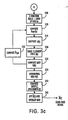
- FIG. 2 illustrates a functional block diagram representing the circuitry for the echo canceller 1 referred to in FIG. 1.
- the circuitry would be implemented in a DSP chip or a microprocessor, though it can be implemented in other ways which are known to one skilled in the art.
- a brief description of the blocks will be given for FIG. 2.
- a more detailed flow diagram and description for the echo cancellation process employed by the circuit of FIG. 2 shall follow thereafter.
- the inputs to the circuit are x ( t ) and y ( t ), y ( t ) representing the incoming speech signal from the far-end speaker and x ( t ) representing the combination of speech signal from the near-end speaker and the echo.
- the well-known normalized cross-correlation estimation between x ( t ) and y ( t ) is performed in block 100 to determine the level of correlation between x ( t ) and y ( t ) which is quantitatively represented by the correlation coefficient C , a value of 1 for C being perfect correlation.
- x ( t ) comprises of only the echo portion which is essentially a delayed form of y ( t ). In that case, there is almost a perfect correlation between x ( t ) and y ( t ) and the C value is near 1.
- the x ( t ) comprises only of the signal and the C value is near 0.
- the C value may be between 0 and 1, but typically near to 0 since the two speech signals will not be highly correlated. And of course, silence would result in a near 0 also, since respective noises will not be highly correlated. Certain decisions are based on whether the C value exceeds certain thresholds.
- the amount of delay is estimated in block 120 by measuring the time shift required to produce the maximum C value. Once the delay is determined, the two channels of inputs are aligned in block 130 by time-shifting y ( t ) to match x ( t ). The amplitude of the x ( t ) and y ( t ) is then normalized in block 140 by first determining a certain gain factor, and then multiplying y ( t ) by the gain factor in block 145.
- the processed form of the input x ( t ) is next processed in blocks 150 through 165; the processed form of the input y ( t ) is next processed 151 through 166. Because both channels are processed in an identical manner which is well known and understood, only a brief description will be provided.
- the well-known Hanning window is applied to the processed inputs. They are then transformed into their respective frequency domain using the well-known fast Fourier transform (FFT), blocks 155 and 156, and then to Bark Scales, P x ( b ) and P y ( b ), using the Bark Frequency Warping technique in blocks 165 and 166.
- FFT fast Fourier transform
- P x ( b ) and P y ( b ) using the Bark Frequency Warping technique in blocks 165 and 166.
- the transfer function H ( b ) is estimated.
- the transfer function is then used in block 175 to normalize P y ( b ), which is then used to estimate the gain G ( b ) which will be used to suppress the echo.
- the Bark Scales are unwarped.
- the gain function is then used to suppress the echo from the input spectrum in block 185.
- the well-known inverse FFT (IFFT) is performed in block 190 and the overlap add in block 195 to yield an echo-free signal.
- M samples (in this case 256 overlap 128, though other values are possible) are taken from the inputs x ( t ) and y ( t ) in step 205 at 16 ms block intervals (8 KHz sampling rate).
- step 210 Sometimes a dc component exists with the inputs and so it is removed, step 210, using a common procedure well known to those skilled in the art.
- T denotes the transpose of a vector.
- step 230 the amount of delay between the two inputs, or D n , is estimated in step 230.
- the present canceller can still function, though not as optimally, even if steps 232, 234, 236, and 240 were eliminated, and step 245 were to be performed immediately after 230 using the same D n each time.
- step 250 an amplitude normalization is performed on the inputs using a gain normalization factor, Z which is initially set at 1, but which is continually updated in step 269 when the stated condition is met.
- ⁇ is near to 0, that indicates either a double-talk or only near-end speech or only silence.
- the coherence factor, ⁇ is used together with a non-linear energy function described in step 267 (see below) to further control the echo suppression.
- step 265 P x and P y are converted to Bark Scales P x ( b ) and P y ( b ) using the well-known Bark Frequency Warping technique.
- the gain normalization factor, Z is updated if the following conditions are met: ⁇ > ⁇ and E n >T n .
- step 275 it is determined whether ⁇ > ⁇ and E n > T n .
- ⁇ 0.65, though a different value may be optimal for ⁇ under different configuration, e.g., different microphone set-up. If the condition in step 275 is met, the transfer function H ( b ) is updated from its initial value of 1 in step 280. If the condition in step 275 is not met, then the step 285 is performed without updating the H ( b ).
- a buffer is provided to store M old values of P ⁇ y ( b ).
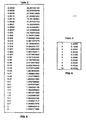
- the value of G s is found by referring to lookup Table 1 using the current value for ⁇ .
- steps 310, 315, 320, 325 and 330 are repeatedly performed for each sample block of input, each loop producing an updated value for the parameters involved.
- step 335 the G ( b ) is unwarped to produce G ( f ).
- step 345 the well-known inverse FFT (IFFT) and overlap add are performed on X ⁇ ( f ) and to produce an echo-free signal X ⁇ ( t ).
- IFFT inverse FFT
- the cross-correlation estimation technique employed here may be substituted with other techniques for determining the correction between two signals.
- the amplitude normalisation, the use of Hanning Window and Bark Scales while contributing to the effectiveness of the preferred embodiment of the present invention, may be eliminated under some circumstances without completely negating the function of the present invention.
- the Bark Scales are used in this case as way of reducing computation time and, therefore, may not unduly affect the performance of the present echo canceller.
- the Hanning Window was found to be optimal in this case, it may be replaced with other windows.
Landscapes
- Engineering & Computer Science (AREA)
- Signal Processing (AREA)
- Cable Transmission Systems, Equalization Of Radio And Reduction Of Echo (AREA)
Claims (14)
- Akustischer Echokompensator (1) für ein Telekommunikationssystem, das für eine Kommunikation zwischen einem Sprecher an einem fernen Ende und einem Sprecher (30) an einem nahen Ende ausgelegt ist, wobei das System ein Mikrophon (25) und einen Lautsprecher (23) aufweist, wobei das Mikrophon (25) ein Sprachsignal von dem Sprecher (30) an dem nahen Ende und ein Echosignal eines Sprachsignals von dem Sprecher an dem fernen Ende erhält, das von dem Lautsprecher (23) stammt, wobei der Echokompensator (1) umfaßt:ein Mittel, das zum Sammeln von Proben zweier Eingaben x(t) und y(t) von dem Telekommunikationssystem ausgelegt ist, wobei y(t) das Sprachsignal von dem Sprecher an dem fernen Ende ist und wobei x(t) eine Kombination des Sprachsignals des Sprechers an dem nahen Ende und dem Echosignal von y(t) ist;ein Mittel (100), das ausgelegt ist, um eine Korrelation zwischen x(t) und y(t) zu berechnen;ein Mittel (120), das ausgelegt ist, um eine Verzögerung zwischen x(t) und y(t) zu berechnen;ein Mittel (130), das ausgelegt ist, um x(t) und y(t) durch Zeitversetzung durch die Verzögerung zwischen x(t) und y(t) auszurichten;wobei der Echokompensator dadurch gekennzeichnet ist, daß er umfaßt:ein Mittel, das ausgelegt ist, das x(t)-Signal und das zeitversetzte y(t)-Signal in deren Spektren in einem Frequenzbereich zu transformieren;ein Mittel (170), das ausgelegt ist, eine Transferfunktion unter Verwendung des Spektrums von x(t) und des Spektrums des zeitversetzten y(t) zu berechnen, und das ausgelegt ist, das Spektrum des zeitversetzten y(t) unter Verwendung der Transferfunktion zu normieren;ein Mittel (175), das ausgelegt ist, um eine Verstärkungsfunktion unter Verwendung des Spektrums x(t) und des normierten Spektrums des zeitversetzten y(t) zu berechnen;ein Mittel, das ausgelegt ist, das Spektrum von x(t) durch die Verstärkungsfunktion zu vervielfachen;und ein Mittel, das ausgelegt ist, das resultierende Spektrum in ein Zeitbereichssignal zu transformieren, das ein Echo freies Signal herstellt.
- Echokompensator (1) nach Anspruch 1, des weiteren ein Mittel zur Anwendung eines Hann-Fensters (150, 151) umfassend.
- Echokompensator (1) nach Anspruch 1 oder 2, des weiteren ein Mittel (165, 166), das für Bark-Skala-Skalierung ausgelegt ist, und Mittel (180) umfassend, das für Bark-Skala-Reskalierung ausgelegt ist.
- Echokompensator (1) nach einem der vorangehenden Ansprüche, wobei 256 Proben gesammelt werden, die 128 Proben in 16ms Blockintervallen überlappen.
- Echokompensator (1) nach einem der vorangehenden Ansprüche, des weiteren umfassend ein Mittel (195), das für einen Überlappungszusatz ausgelegt ist.
- Verfahren zum Löschen eines akustischen Echos in einem Telekommunikationssystem, das zur Kommunikation zwischen einem Sprecher an einem fernen Ende und einem Sprecher (30) an einem nahen Ende ausgelegt ist, wobei das System ein Mikrophon (25) und einen Lautsprecher (23) aufweist, wobei das Mikrophon (25) ein Sprachsignal des Sprechers (30) an dem nahen Ende und ein Echosignal des Sprechers an dem fernen Ende erhält, welches von dem Lautsprecher (23) stammt, wobei das Verfahren die Schritte umfaßt:(a) Sammeln (295) von Proben zweier Eingaben, x(t) und y(t), von dem Telekommunikationssystem, wobei y(t) das Sprachsignal des Sprechers an dem fernen Ende ist, wobei x(t) eine Kombination des Sprachsignals von dem Sprecher (30) an dem nahen Ende und des Echosignals von dem y(t) ist;(b) Berechnen (220) einer Korrelation zwischen x(t) und y(t);(c) Berechnen (230) einer Verzögerung zwischen x(t) und y(t);(d) Ausrichten (245) von x(t) und y(t) durch Zeitversetzen von y(t) durch die in Schritt c) berechnete Verzögerung;wobei das Verfahren dadurch gekennzeichnet ist, daß es die folgenden Schritte umfaßt:(e) Transformieren (255) des x(t)-Signals und des zeitversetzten y(t)-Signals in deren Spektren in einem Frequenzbereich;(f) Berechnen einer Transferfunktion unter Verwendung des Spektrums von x(t) und des Spektrums des zeitversetzten y(t);(g) Normieren des Spektrums des zeitversetzten y(t) unter Verwendung der Transferfunktion;(h) Berechnen (325) einer Verstärkungsfunktion unter Verwendung des Spektrums von x(t) und des normierten Spektrums des zeitversetzten y(t);(i) Vervielfachen (340) des Spektrums von x(t) durch die Verstärkungsfunktion; und(j) Transformieren (345) des resultierenden Spektrums des Schritts i) in ein Zeitbereichssignal, das ein Echo freies Signal erzeugt.
- Verfahren nach Anspruch 6, des weiteren umfassend den Schritt des Anwendens (255) eines Hann-Fensters nach Schritt d).
- Verfahren nach Anspruch 6 oder 7, des weiteren umfassend den Schritt der Bark-Skala-Skalierung (265) des Spektrums nach Schritt e) und der Bark-Skala-Reskalierung (335) nach Schritt h).
- Verfahren nach einem der Ansprüche 6 bis 8, wobei die 256 Proben gesammelt werden, die 128 Proben in 16ms Blockintervallen überlappen.
- Verfahren nach einem der Ansprüche 6 bis 9, des weiteren den Schritt des Ausführens eines Überlappungszusatzes umfassend.
- Akustischer Echokompensator (1) nach einem der Ansprüche 1 bis 5, wobei das Mittel, das zum Transformieren der Signale in deren Spektren ausgelegt ist, des weiteren umfaßt:ein Mittel (140), das ausgelegt ist, um eine Amplitude von x(t) und des zeitversetzten y(t) zu normieren;ein Mittel (150), das ausgelegt ist, ein Hann-Fenster anzuwenden und das normierte x(t)-Signal und das normierte zeitversetzte y(t)-Signal in einen Frequenzbereich zu transformieren, wo X(f)=xr(f) + jxi(f) und Y(f)=yr(f) + jyi(f) und wo X(f)=FFT(x) und Y(f)=FFT(y);ein Mittel (155, 156), das ausgelegt ist, ein Leistungsspektrum Px und Py zu berechnen, wo Px = |xr (f)|+|xi (f)|+ε|xr (f)||xi (f)| und Py =|yr (f)|+|yi (f)|+ε|yr (f)||yi (f)|, wobei ε ein Skalierungsfaktor ist, welcher die Menge des zu unterdrückenden Echos und des Rauschens steuert;ein Mittel (165, 166) zur Bark-Skala-Skalierung von Px und Py, um Px(b) und Py(b) zu erhalten;wobei das Mittel, das zur Berechnung der Transferfunktion ausgelegt ist, des weiteren umfaßt:ein Mittel (170), das zur Berechnung einer Transferfunktion H(b) und zur Normierung von Py(b) durch die Transferfunktion ausgelegt ist;wobei das Mittel zur Berechnung der Verstärkungsfunktion des weiteren umfaßt:ein Mittel (175), das zur Berechung einer Verstärkungsfunktion G(b) ausgelegt ist, wobei G(b) von Px(b) und Py(b) berechnet wird;wobei das Mittel zur Vervielfachung des weiteren umfaßt:ein Mittel (180), das zur Bark-Skala-Skalierung von G(b) ausgelegt ist, um G(f) zu erhalten;ein Mittel, das zur Vervielfachung des Signals X(f) durch die Verstärkungsfunktion G(f) ausgelegt ist, um X̃(f) zu erhalten; undwobei das Mittel, das zum Transformieren in ein Zeitbereichssignal ausgelegt ist, des weiteren umfaßt:ein Mittel (190), das zum Ausführen eines inversen Transformierungs- und Überlappungszusatzes ausgelegt ist, um das Signal X̃(f) umzuwandeln, um ein Echo freies Signal X̃(t) zu erhalten.
- Akustischer Echokompensator nach Anspruch 11, des weiteren umfassend ein Mittel, das ausgelegt ist, um die Verzögerung zu aktualisieren, wobei die Verzögerung basierend auf einem Wert der Korrelation zwischen x(t) und y(t) aktualisiert wird.
- Akustischer Echokompensator nach Anspruch 11 oder 12, wobei H(b) wie folgt berechnet wird:

wobei α < 1. - Akustischer Echokompensator nach einem der Ansprüche 11 bis 13, wobei

wo L̅ (b) ein Faktor ist, der hinsichtlich Lb variiert, wobei Lb = Rrpr (b)Rpo (b);
wo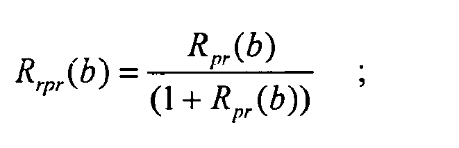
wo
γ ist ein Glättungsfaktor mit γ <1;
und P̅rpo hat anfänglich einen Wert von 0;

und
wo P̅y (b) eine normierte Bark-Skala Py(b) ist;
wo Gs ein Faktor ist, der hinsichtlich des Koheränzfaktors Φ variiert, wobei
Applications Claiming Priority (2)
| Application Number | Priority Date | Filing Date | Title |
|---|---|---|---|
| SG9702744 | 1997-08-01 | ||
| SG1997002744A SG71035A1 (en) | 1997-08-01 | 1997-08-01 | Acoustic echo canceller |
Publications (4)
| Publication Number | Publication Date |
|---|---|
| EP0895397A2 EP0895397A2 (de) | 1999-02-03 |
| EP0895397A3 EP0895397A3 (de) | 1999-08-18 |
| EP0895397B1 EP0895397B1 (de) | 2006-08-23 |
| EP0895397B9 true EP0895397B9 (de) | 2007-01-17 |
Family
ID=20429709
Family Applications (1)
| Application Number | Title | Priority Date | Filing Date |
|---|---|---|---|
| EP98306066A Expired - Lifetime EP0895397B9 (de) | 1997-08-01 | 1998-07-30 | Akustischer Echokompensator |
Country Status (4)
| Country | Link |
|---|---|
| US (1) | US6249581B1 (de) |
| EP (1) | EP0895397B9 (de) |
| DE (1) | DE69835644T2 (de) |
| SG (1) | SG71035A1 (de) |
Cited By (1)
| Publication number | Priority date | Publication date | Assignee | Title |
|---|---|---|---|---|
| CN109448748A (zh) * | 2018-12-17 | 2019-03-08 | 杭州嘉楠耘智信息科技有限公司 | 一种用于回声消除的滤波方法及装置、设备、介质 |
Families Citing this family (34)
| Publication number | Priority date | Publication date | Assignee | Title |
|---|---|---|---|---|
| DE19850272A1 (de) * | 1998-10-31 | 2000-05-04 | Alcatel Sa | Verfahren zur Verbesserung der Echounterdrückung in einem Telekommunikaionssystem |
| FR2802367B1 (fr) * | 1999-12-14 | 2006-08-18 | France Telecom | Procede temps reel de traitement et de gestion pour l'annulation d'echo entre haut-parleur et microphone d'un terminal informatique |
| AU3039900A (en) | 1999-12-17 | 2001-06-25 | Nokia Corporation | A delay measurement system in a packet network |
| US6622030B1 (en) | 2000-06-29 | 2003-09-16 | Ericsson Inc. | Echo suppression using adaptive gain based on residual echo energy |
| US6766019B1 (en) * | 2000-07-21 | 2004-07-20 | Agere Systems Inc. | Method and apparatus for performing double-talk detection in acoustic echo cancellation |
| DE10043064B4 (de) * | 2000-09-01 | 2004-07-08 | Dietmar Dr. Ruwisch | Verfahren und Vorrichtung zur Elimination von Lautsprecherinterferenzen aus Mikrofonsignalen |
| EP1372516B1 (de) | 2001-02-27 | 2009-05-13 | Smith & Nephew, Inc. | Chirurgisches navigationssystem zur teilweisen kniegelenkrekonstruktion |
| US7547307B2 (en) * | 2001-02-27 | 2009-06-16 | Smith & Nephew, Inc. | Computer assisted knee arthroplasty instrumentation, systems, and processes |
| US6889066B2 (en) * | 2001-03-27 | 2005-05-03 | Qualcomm Incorporated | Network echo suppression in mobile stations |
| JP2004537232A (ja) * | 2001-07-20 | 2004-12-09 | コーニンクレッカ フィリップス エレクトロニクス エヌ ヴィ | 多数のマイクロフォンのエコーを抑圧する回路をポストプロセッサとして有する音響補強システム |
| EP1413168A2 (de) * | 2001-07-20 | 2004-04-28 | Koninklijke Philips Electronics N.V. | Schallverstärkungsystem mit echounterdrücker und lautsprecherstrahlformer |
| JP2005516724A (ja) | 2002-02-11 | 2005-06-09 | スミス アンド ネフュー インコーポレーテッド | 画像案内式骨折整復 |
| US7409057B1 (en) * | 2002-07-03 | 2008-08-05 | Marvell International Ltd. | Nonlinear echo compensator for class B transmitter line driver |
| US7272224B1 (en) * | 2003-03-03 | 2007-09-18 | Apple Inc. | Echo cancellation |
| US7363334B2 (en) * | 2003-08-28 | 2008-04-22 | Accoutic Processing Technology, Inc. | Digital signal-processing structure and methodology featuring engine-instantiated, wave-digital-filter componentry, and fabrication thereof |
| US20050065778A1 (en) * | 2003-09-24 | 2005-03-24 | Mastrianni Steven J. | Secure speech |
| US7862570B2 (en) | 2003-10-03 | 2011-01-04 | Smith & Nephew, Inc. | Surgical positioners |
| US7764985B2 (en) | 2003-10-20 | 2010-07-27 | Smith & Nephew, Inc. | Surgical navigation system component fault interfaces and related processes |
| US7794467B2 (en) | 2003-11-14 | 2010-09-14 | Smith & Nephew, Inc. | Adjustable surgical cutting systems |
| EP1729665A1 (de) | 2004-03-31 | 2006-12-13 | Smith and Nephew, Inc. | Verfahren und geräte zur bereitstellung einer referenz-array-eingabevorrichtung |
| EP1737375B1 (de) | 2004-04-21 | 2021-08-11 | Smith & Nephew, Inc | Computerunterstützte navigationssysteme für die schulter-arthroplastie |
| US7395790B2 (en) * | 2004-11-18 | 2008-07-08 | S&S Cycle, Inc. | Reed valve breather for evolution engine |
| US8177788B2 (en) | 2005-02-22 | 2012-05-15 | Smith & Nephew, Inc. | In-line milling system |
| WO2006111370A1 (en) * | 2005-04-19 | 2006-10-26 | Epfl (Ecole Polytechnique Federale De Lausanne) | A method and device for removing echo in a multi-channel audio signal |
| US7647077B2 (en) | 2005-05-31 | 2010-01-12 | Bitwave Pte Ltd | Method for echo control of a wireless headset |
| US7856098B1 (en) * | 2005-09-15 | 2010-12-21 | Mindspeed Technologies, Inc. | Echo cancellation and control in discrete cosine transform domain |
| DE102008039329A1 (de) * | 2008-01-25 | 2009-07-30 | Fraunhofer-Gesellschaft zur Förderung der angewandten Forschung e.V. | Vorrichtung und Verfahren zur Berechnung von Steuerinformationen für ein Echounterdrückungsfilter und Vorrichtung und Verfahren zur Berechnung eines Verzögerungswerts |
| NO332437B1 (no) * | 2010-01-18 | 2012-09-17 | Cisco Systems Int Sarl | Apparat og fremgangsmate for a supprimere et akustisk ekko |
| WO2012158163A1 (en) * | 2011-05-17 | 2012-11-22 | Google Inc. | Non-linear post-processing for acoustic echo cancellation |
| US9065895B2 (en) * | 2012-02-22 | 2015-06-23 | Broadcom Corporation | Non-linear echo cancellation |
| US9628141B2 (en) * | 2012-10-23 | 2017-04-18 | Interactive Intelligence Group, Inc. | System and method for acoustic echo cancellation |
| US9083782B2 (en) * | 2013-05-08 | 2015-07-14 | Blackberry Limited | Dual beamform audio echo reduction |
| CN103414453B (zh) * | 2013-08-19 | 2016-02-24 | 北京无线电计量测试研究所 | 一种频率源短稳参数数字化检测方法及装置 |
| CN111917926B (zh) * | 2019-05-09 | 2021-08-06 | 上海触乐信息科技有限公司 | 一种通信终端中的回声消除方法、装置及终端设备 |
Family Cites Families (12)
| Publication number | Priority date | Publication date | Assignee | Title |
|---|---|---|---|---|
| US3699271A (en) * | 1970-11-16 | 1972-10-17 | Bell Telephone Labor Inc | Speech processor using multiband controlled center clipping |
| US3784747A (en) * | 1971-12-03 | 1974-01-08 | Bell Telephone Labor Inc | Speech suppression by predictive filtering |
| DE3118473C2 (de) * | 1981-05-09 | 1987-02-05 | Felten & Guilleaume Fernmeldeanlagen GmbH, 8500 Nürnberg | Verfahren zur Aufbereitung elektrischer Signale mit einer digitalen Filteranordnung |
| US4644108A (en) * | 1982-10-27 | 1987-02-17 | International Business Machines Corporation | Adaptive sub-band echo suppressor |
| US4562312A (en) * | 1983-02-17 | 1985-12-31 | At&T Bell Laboratories | Subsampling delay estimator for an echo canceler |
| CA1332187C (en) * | 1986-10-30 | 1994-09-27 | Fumio Amano | Echo canceller with short processing delay and decreased multiplication number |
| NL8701633A (nl) * | 1987-07-10 | 1989-02-01 | Philips Nv | Digitale echocompensator. |
| US5588089A (en) * | 1990-10-23 | 1996-12-24 | Koninklijke Ptt Nederland N.V. | Bark amplitude component coder for a sampled analog signal and decoder for the coded signal |
| US5450522A (en) * | 1991-08-19 | 1995-09-12 | U S West Advanced Technologies, Inc. | Auditory model for parametrization of speech |
| DE4316297C1 (de) * | 1993-05-14 | 1994-04-07 | Fraunhofer Ges Forschung | Frequenzanalyseverfahren |
| WO1995028034A2 (en) * | 1994-04-12 | 1995-10-19 | Philips Electronics N.V. | Signal amplifier system with improved echo cancellation |
| US5659619A (en) * | 1994-05-11 | 1997-08-19 | Aureal Semiconductor, Inc. | Three-dimensional virtual audio display employing reduced complexity imaging filters |
-
1997
- 1997-08-01 SG SG1997002744A patent/SG71035A1/en unknown
-
1998
- 1998-07-29 US US09/124,804 patent/US6249581B1/en not_active Expired - Lifetime
- 1998-07-30 DE DE69835644T patent/DE69835644T2/de not_active Expired - Fee Related
- 1998-07-30 EP EP98306066A patent/EP0895397B9/de not_active Expired - Lifetime
Cited By (2)
| Publication number | Priority date | Publication date | Assignee | Title |
|---|---|---|---|---|
| CN109448748A (zh) * | 2018-12-17 | 2019-03-08 | 杭州嘉楠耘智信息科技有限公司 | 一种用于回声消除的滤波方法及装置、设备、介质 |
| CN109448748B (zh) * | 2018-12-17 | 2021-08-03 | 嘉楠明芯(北京)科技有限公司 | 一种用于回声消除的滤波方法及装置、设备、介质 |
Also Published As
| Publication number | Publication date |
|---|---|
| US6249581B1 (en) | 2001-06-19 |
| EP0895397B1 (de) | 2006-08-23 |
| DE69835644T2 (de) | 2007-08-23 |
| EP0895397A2 (de) | 1999-02-03 |
| DE69835644D1 (de) | 2006-10-05 |
| SG71035A1 (en) | 2000-03-21 |
| EP0895397A3 (de) | 1999-08-18 |
Similar Documents
| Publication | Publication Date | Title |
|---|---|---|
| EP0895397B9 (de) | Akustischer Echokompensator | |
| US7742592B2 (en) | Method and device for removing echo in an audio signal | |
| US8594320B2 (en) | Hybrid echo and noise suppression method and device in a multi-channel audio signal | |
| CN110838300B (zh) | 回声消除的处理方法及处理系统 | |
| EP0843934B1 (de) | Einrichtung zur unterdrückung einer störenden komponente eines eingangssignals | |
| US7062040B2 (en) | Suppression of echo signals and the like | |
| JP2936101B2 (ja) | デジタルエコーキャンセラ | |
| US7684559B2 (en) | Acoustic echo suppressor for hands-free speech communication | |
| EP1855457B1 (de) | Kompensation von Mehrkanalechos durch Dekorrelation | |
| JP2538176B2 (ja) | エコ―制御装置 | |
| US9426279B2 (en) | Systems and methods for echo cancellation and echo suppression | |
| JP4975073B2 (ja) | デジタル適応フィルタと同フィルタを用いたアコスティックエコーキャンセラ | |
| EP0932142B1 (de) | Integriertes System zur Sprachverbesserung in einem Fahrzeug sowie Freisprech-Mobilfunksystem | |
| EP0769867A2 (de) | Akustischer Teilband-Echokompensator | |
| JP2009065699A (ja) | 音響エコーの相殺および抑制を実行する利得制御方法 | |
| US20030185402A1 (en) | Adaptive distortion manager for use with an acoustic echo canceler and a method of operation thereof | |
| JP3420705B2 (ja) | エコー抑圧方法及び装置並びにエコー抑圧プログラムが記憶されたコンピュータに読取り可能な記憶媒体 | |
| CN106533500A (zh) | 一种优化回声消除器收敛特性的方法 | |
| JP3507020B2 (ja) | 反響抑圧方法、反響抑圧装置及び反響抑圧プログラム記憶媒体 | |
| US6834108B1 (en) | Method for improving acoustic noise attenuation in hand-free devices | |
| US20080267420A1 (en) | Methods and systems for reducing acoustic echoes in multichannel audio-communication systems | |
| JP3756839B2 (ja) | 反響低減方法、反響低減装置、反響低減プログラム | |
| US6694020B1 (en) | Frequency domain stereophonic acoustic echo canceller utilizing non-linear transformations | |
| Mohammed | A new adaptive beamformer for optimal acoustic echo and noise cancellation with less computational load | |
| US8369511B2 (en) | Robust method of echo suppressor |
Legal Events
| Date | Code | Title | Description |
|---|---|---|---|
| PUAI | Public reference made under article 153(3) epc to a published international application that has entered the european phase |
Free format text: ORIGINAL CODE: 0009012 |
|
| AK | Designated contracting states |
Kind code of ref document: A2 Designated state(s): DE ES FR GB IT |
|
| AX | Request for extension of the european patent |
Free format text: AL;LT;LV;MK;RO;SI |
|
| PUAL | Search report despatched |
Free format text: ORIGINAL CODE: 0009013 |
|
| AK | Designated contracting states |
Kind code of ref document: A3 Designated state(s): AT BE CH CY DE DK ES FI FR GB GR IE IT LI LU MC NL PT SE |
|
| AX | Request for extension of the european patent |
Free format text: AL;LT;LV;MK;RO;SI |
|
| 17P | Request for examination filed |
Effective date: 20000115 |
|
| AKX | Designation fees paid |
Free format text: DE ES FR GB IT |
|
| 17Q | First examination report despatched |
Effective date: 20040129 |
|
| GRAP | Despatch of communication of intention to grant a patent |
Free format text: ORIGINAL CODE: EPIDOSNIGR1 |
|
| GRAS | Grant fee paid |
Free format text: ORIGINAL CODE: EPIDOSNIGR3 |
|
| GRAA | (expected) grant |
Free format text: ORIGINAL CODE: 0009210 |
|
| AK | Designated contracting states |
Kind code of ref document: B1 Designated state(s): DE ES FR GB IT |
|
| PG25 | Lapsed in a contracting state [announced via postgrant information from national office to epo] |
Ref country code: IT Free format text: LAPSE BECAUSE OF FAILURE TO SUBMIT A TRANSLATION OF THE DESCRIPTION OR TO PAY THE FEE WITHIN THE PRESCRIBED TIME-LIMIT;WARNING: LAPSES OF ITALIAN PATENTS WITH EFFECTIVE DATE BEFORE 2007 MAY HAVE OCCURRED AT ANY TIME BEFORE 2007. THE CORRECT EFFECTIVE DATE MAY BE DIFFERENT FROM THE ONE RECORDED. Effective date: 20060823 |
|
| REG | Reference to a national code |
Ref country code: GB Ref legal event code: FG4D |
|
| REF | Corresponds to: |
Ref document number: 69835644 Country of ref document: DE Date of ref document: 20061005 Kind code of ref document: P |
|
| PG25 | Lapsed in a contracting state [announced via postgrant information from national office to epo] |
Ref country code: ES Free format text: LAPSE BECAUSE OF FAILURE TO SUBMIT A TRANSLATION OF THE DESCRIPTION OR TO PAY THE FEE WITHIN THE PRESCRIBED TIME-LIMIT Effective date: 20061204 |
|
| ET | Fr: translation filed | ||
| REG | Reference to a national code |
Ref country code: FR Ref legal event code: CA |
|
| PLBE | No opposition filed within time limit |
Free format text: ORIGINAL CODE: 0009261 |
|
| STAA | Information on the status of an ep patent application or granted ep patent |
Free format text: STATUS: NO OPPOSITION FILED WITHIN TIME LIMIT |
|
| 26N | No opposition filed |
Effective date: 20070524 |
|
| PGFP | Annual fee paid to national office [announced via postgrant information from national office to epo] |
Ref country code: DE Payment date: 20080731 Year of fee payment: 11 |
|
| PGFP | Annual fee paid to national office [announced via postgrant information from national office to epo] |
Ref country code: FR Payment date: 20080630 Year of fee payment: 11 |
|
| PGFP | Annual fee paid to national office [announced via postgrant information from national office to epo] |
Ref country code: GB Payment date: 20080704 Year of fee payment: 11 |
|
| GBPC | Gb: european patent ceased through non-payment of renewal fee |
Effective date: 20090730 |
|
| REG | Reference to a national code |
Ref country code: FR Ref legal event code: ST Effective date: 20100331 |
|
| PG25 | Lapsed in a contracting state [announced via postgrant information from national office to epo] |
Ref country code: FR Free format text: LAPSE BECAUSE OF NON-PAYMENT OF DUE FEES Effective date: 20090731 |
|
| PG25 | Lapsed in a contracting state [announced via postgrant information from national office to epo] |
Ref country code: GB Free format text: LAPSE BECAUSE OF NON-PAYMENT OF DUE FEES Effective date: 20090730 |
|
| PG25 | Lapsed in a contracting state [announced via postgrant information from national office to epo] |
Ref country code: DE Free format text: LAPSE BECAUSE OF NON-PAYMENT OF DUE FEES Effective date: 20100202 |