EP0927595B1 - Entzundern von Metallen durch einen Laser mit sehr kurzer Pulsbreite und hoher Durchschnittsleistung - Google Patents
Entzundern von Metallen durch einen Laser mit sehr kurzer Pulsbreite und hoher Durchschnittsleistung Download PDFInfo
- Publication number
- EP0927595B1 EP0927595B1 EP97122937A EP97122937A EP0927595B1 EP 0927595 B1 EP0927595 B1 EP 0927595B1 EP 97122937 A EP97122937 A EP 97122937A EP 97122937 A EP97122937 A EP 97122937A EP 0927595 B1 EP0927595 B1 EP 0927595B1
- Authority
- EP
- European Patent Office
- Prior art keywords
- laser
- oxide
- radiation
- strip
- focused
- Prior art date
- Legal status (The legal status is an assumption and is not a legal conclusion. Google has not performed a legal analysis and makes no representation as to the accuracy of the status listed.)
- Expired - Lifetime
Links
- 229910052751 metal Inorganic materials 0.000 title claims abstract description 83
- 239000002184 metal Substances 0.000 title claims abstract description 83
- 230000005855 radiation Effects 0.000 claims abstract description 76
- 230000003287 optical effect Effects 0.000 claims abstract description 50
- 238000000034 method Methods 0.000 claims abstract description 45
- 230000008016 vaporization Effects 0.000 claims abstract description 19
- 239000003574 free electron Substances 0.000 claims abstract description 16
- 238000009834 vaporization Methods 0.000 claims abstract description 16
- 230000005670 electromagnetic radiation Effects 0.000 claims abstract description 10
- 230000003993 interaction Effects 0.000 claims abstract description 9
- 238000009826 distribution Methods 0.000 claims description 15
- 230000001590 oxidative effect Effects 0.000 claims description 10
- 238000000265 homogenisation Methods 0.000 claims description 8
- 210000001747 pupil Anatomy 0.000 claims 1
- 238000010408 sweeping Methods 0.000 claims 1
- 230000008569 process Effects 0.000 abstract description 24
- 229910000831 Steel Inorganic materials 0.000 abstract description 12
- 239000010959 steel Substances 0.000 abstract description 12
- 239000007789 gas Substances 0.000 description 22
- 239000002245 particle Substances 0.000 description 14
- 230000008901 benefit Effects 0.000 description 13
- 239000002253 acid Substances 0.000 description 12
- 239000011261 inert gas Substances 0.000 description 11
- 239000000463 material Substances 0.000 description 10
- 238000005554 pickling Methods 0.000 description 10
- 239000000835 fiber Substances 0.000 description 8
- 230000007246 mechanism Effects 0.000 description 8
- 229910052782 aluminium Inorganic materials 0.000 description 7
- XAGFODPZIPBFFR-UHFFFAOYSA-N aluminium Chemical compound [Al] XAGFODPZIPBFFR-UHFFFAOYSA-N 0.000 description 7
- -1 hydrofluoric Chemical class 0.000 description 7
- 238000010521 absorption reaction Methods 0.000 description 6
- 238000012545 processing Methods 0.000 description 6
- 238000001228 spectrum Methods 0.000 description 6
- 238000005422 blasting Methods 0.000 description 5
- 238000006243 chemical reaction Methods 0.000 description 5
- 229910044991 metal oxide Inorganic materials 0.000 description 5
- 150000004706 metal oxides Chemical class 0.000 description 5
- 239000000126 substance Substances 0.000 description 5
- XKRFYHLGVUSROY-UHFFFAOYSA-N Argon Chemical compound [Ar] XKRFYHLGVUSROY-UHFFFAOYSA-N 0.000 description 4
- UQSXHKLRYXJYBZ-UHFFFAOYSA-N Iron oxide Chemical compound [Fe]=O UQSXHKLRYXJYBZ-UHFFFAOYSA-N 0.000 description 4
- PXHVJJICTQNCMI-UHFFFAOYSA-N Nickel Chemical compound [Ni] PXHVJJICTQNCMI-UHFFFAOYSA-N 0.000 description 4
- 230000001154 acute effect Effects 0.000 description 4
- 230000007613 environmental effect Effects 0.000 description 4
- 239000013307 optical fiber Substances 0.000 description 4
- QVGXLLKOCUKJST-UHFFFAOYSA-N atomic oxygen Chemical compound [O] QVGXLLKOCUKJST-UHFFFAOYSA-N 0.000 description 3
- 239000010953 base metal Substances 0.000 description 3
- 238000010438 heat treatment Methods 0.000 description 3
- 238000007654 immersion Methods 0.000 description 3
- JEIPFZHSYJVQDO-UHFFFAOYSA-N iron(III) oxide Inorganic materials O=[Fe]O[Fe]=O JEIPFZHSYJVQDO-UHFFFAOYSA-N 0.000 description 3
- 238000004519 manufacturing process Methods 0.000 description 3
- TWNQGVIAIRXVLR-UHFFFAOYSA-N oxo(oxoalumanyloxy)alumane Chemical compound O=[Al]O[Al]=O TWNQGVIAIRXVLR-UHFFFAOYSA-N 0.000 description 3
- 239000001301 oxygen Substances 0.000 description 3
- 229910052760 oxygen Inorganic materials 0.000 description 3
- 239000000843 powder Substances 0.000 description 3
- 229910001220 stainless steel Inorganic materials 0.000 description 3
- 239000010935 stainless steel Substances 0.000 description 3
- PFNQVRZLDWYSCW-UHFFFAOYSA-N (fluoren-9-ylideneamino) n-naphthalen-1-ylcarbamate Chemical compound C12=CC=CC=C2C2=CC=CC=C2C1=NOC(=O)NC1=CC=CC2=CC=CC=C12 PFNQVRZLDWYSCW-UHFFFAOYSA-N 0.000 description 2
- 229910000976 Electrical steel Inorganic materials 0.000 description 2
- VEXZGXHMUGYJMC-UHFFFAOYSA-N Hydrochloric acid Chemical compound Cl VEXZGXHMUGYJMC-UHFFFAOYSA-N 0.000 description 2
- 229910001209 Low-carbon steel Inorganic materials 0.000 description 2
- 150000007513 acids Chemical class 0.000 description 2
- 238000000137 annealing Methods 0.000 description 2
- 229910052786 argon Inorganic materials 0.000 description 2
- 238000004364 calculation method Methods 0.000 description 2
- 238000005266 casting Methods 0.000 description 2
- 238000010894 electron beam technology Methods 0.000 description 2
- 238000005242 forging Methods 0.000 description 2
- 230000004927 fusion Effects 0.000 description 2
- 239000001307 helium Substances 0.000 description 2
- 229910052734 helium Inorganic materials 0.000 description 2
- SWQJXJOGLNCZEY-UHFFFAOYSA-N helium atom Chemical compound [He] SWQJXJOGLNCZEY-UHFFFAOYSA-N 0.000 description 2
- 238000013532 laser treatment Methods 0.000 description 2
- 229910052759 nickel Inorganic materials 0.000 description 2
- 238000002203 pretreatment Methods 0.000 description 2
- 230000001681 protective effect Effects 0.000 description 2
- 230000035939 shock Effects 0.000 description 2
- VYZAMTAEIAYCRO-UHFFFAOYSA-N Chromium Chemical compound [Cr] VYZAMTAEIAYCRO-UHFFFAOYSA-N 0.000 description 1
- RYGMFSIKBFXOCR-UHFFFAOYSA-N Copper Chemical compound [Cu] RYGMFSIKBFXOCR-UHFFFAOYSA-N 0.000 description 1
- CWYNVVGOOAEACU-UHFFFAOYSA-N Fe2+ Chemical compound [Fe+2] CWYNVVGOOAEACU-UHFFFAOYSA-N 0.000 description 1
- 229910000677 High-carbon steel Inorganic materials 0.000 description 1
- 229910000954 Medium-carbon steel Inorganic materials 0.000 description 1
- 239000004743 Polypropylene Substances 0.000 description 1
- VYPSYNLAJGMNEJ-UHFFFAOYSA-N Silicium dioxide Chemical compound O=[Si]=O VYPSYNLAJGMNEJ-UHFFFAOYSA-N 0.000 description 1
- RTAQQCXQSZGOHL-UHFFFAOYSA-N Titanium Chemical compound [Ti] RTAQQCXQSZGOHL-UHFFFAOYSA-N 0.000 description 1
- 239000005083 Zinc sulfide Substances 0.000 description 1
- 238000002679 ablation Methods 0.000 description 1
- 230000001133 acceleration Effects 0.000 description 1
- 229910045601 alloy Inorganic materials 0.000 description 1
- 239000000956 alloy Substances 0.000 description 1
- PNEYBMLMFCGWSK-UHFFFAOYSA-N aluminium oxide Inorganic materials [O-2].[O-2].[O-2].[Al+3].[Al+3] PNEYBMLMFCGWSK-UHFFFAOYSA-N 0.000 description 1
- UAIXRPCCYXNJMQ-RZIPZOSSSA-N buprenorphine hydrochlorie Chemical compound [Cl-].C([C@]12[C@H]3OC=4C(O)=CC=C(C2=4)C[C@@H]2[C@]11CC[C@]3([C@H](C1)[C@](C)(O)C(C)(C)C)OC)C[NH+]2CC1CC1 UAIXRPCCYXNJMQ-RZIPZOSSSA-N 0.000 description 1
- WUKWITHWXAAZEY-UHFFFAOYSA-L calcium difluoride Chemical compound [F-].[F-].[Ca+2] WUKWITHWXAAZEY-UHFFFAOYSA-L 0.000 description 1
- 229910001634 calcium fluoride Inorganic materials 0.000 description 1
- 229910052804 chromium Inorganic materials 0.000 description 1
- 239000011651 chromium Substances 0.000 description 1
- 238000004140 cleaning Methods 0.000 description 1
- 230000001427 coherent effect Effects 0.000 description 1
- 230000000052 comparative effect Effects 0.000 description 1
- 230000006835 compression Effects 0.000 description 1
- 238000007906 compression Methods 0.000 description 1
- 238000010924 continuous production Methods 0.000 description 1
- 229910052802 copper Inorganic materials 0.000 description 1
- 239000010949 copper Substances 0.000 description 1
- 229910052593 corundum Inorganic materials 0.000 description 1
- 238000005336 cracking Methods 0.000 description 1
- 230000007423 decrease Effects 0.000 description 1
- 238000002716 delivery method Methods 0.000 description 1
- 230000001419 dependent effect Effects 0.000 description 1
- 238000013461 design Methods 0.000 description 1
- 238000011161 development Methods 0.000 description 1
- 235000012489 doughnuts Nutrition 0.000 description 1
- 230000000694 effects Effects 0.000 description 1
- 230000008030 elimination Effects 0.000 description 1
- 238000003379 elimination reaction Methods 0.000 description 1
- 238000005516 engineering process Methods 0.000 description 1
- 239000002360 explosive Substances 0.000 description 1
- 239000011888 foil Substances 0.000 description 1
- 230000006870 function Effects 0.000 description 1
- 239000005350 fused silica glass Substances 0.000 description 1
- 230000005484 gravity Effects 0.000 description 1
- 231100001261 hazardous Toxicity 0.000 description 1
- 238000005098 hot rolling Methods 0.000 description 1
- 230000001678 irradiating effect Effects 0.000 description 1
- 230000007774 longterm Effects 0.000 description 1
- ORUIBWPALBXDOA-UHFFFAOYSA-L magnesium fluoride Chemical compound [F-].[F-].[Mg+2] ORUIBWPALBXDOA-UHFFFAOYSA-L 0.000 description 1
- 229910001635 magnesium fluoride Inorganic materials 0.000 description 1
- 230000008018 melting Effects 0.000 description 1
- 238000002844 melting Methods 0.000 description 1
- 150000002739 metals Chemical class 0.000 description 1
- 238000012986 modification Methods 0.000 description 1
- 230000004048 modification Effects 0.000 description 1
- 230000008450 motivation Effects 0.000 description 1
- 235000021110 pickles Nutrition 0.000 description 1
- 229920001155 polypropylene Polymers 0.000 description 1
- 238000010405 reoxidation reaction Methods 0.000 description 1
- 238000011160 research Methods 0.000 description 1
- 238000012552 review Methods 0.000 description 1
- 238000005096 rolling process Methods 0.000 description 1
- 239000000758 substrate Substances 0.000 description 1
- 239000013077 target material Substances 0.000 description 1
- 239000010936 titanium Substances 0.000 description 1
- 229910052719 titanium Inorganic materials 0.000 description 1
- 231100000331 toxic Toxicity 0.000 description 1
- 230000002588 toxic effect Effects 0.000 description 1
- 238000011282 treatment Methods 0.000 description 1
- 229910001845 yogo sapphire Inorganic materials 0.000 description 1
- 229910052984 zinc sulfide Inorganic materials 0.000 description 1
- DRDVZXDWVBGGMH-UHFFFAOYSA-N zinc;sulfide Chemical compound [S-2].[Zn+2] DRDVZXDWVBGGMH-UHFFFAOYSA-N 0.000 description 1
Images


Classifications
-
- B—PERFORMING OPERATIONS; TRANSPORTING
- B23—MACHINE TOOLS; METAL-WORKING NOT OTHERWISE PROVIDED FOR
- B23K—SOLDERING OR UNSOLDERING; WELDING; CLADDING OR PLATING BY SOLDERING OR WELDING; CUTTING BY APPLYING HEAT LOCALLY, e.g. FLAME CUTTING; WORKING BY LASER BEAM
- B23K26/00—Working by laser beam, e.g. welding, cutting or boring
- B23K26/12—Working by laser beam, e.g. welding, cutting or boring in a special atmosphere, e.g. in an enclosure
- B23K26/127—Working by laser beam, e.g. welding, cutting or boring in a special atmosphere, e.g. in an enclosure in an enclosure
-
- B—PERFORMING OPERATIONS; TRANSPORTING
- B08—CLEANING
- B08B—CLEANING IN GENERAL; PREVENTION OF FOULING IN GENERAL
- B08B7/00—Cleaning by methods not provided for in a single other subclass or a single group in this subclass
- B08B7/0035—Cleaning by methods not provided for in a single other subclass or a single group in this subclass by radiant energy, e.g. UV, laser, light beam or the like
- B08B7/0042—Cleaning by methods not provided for in a single other subclass or a single group in this subclass by radiant energy, e.g. UV, laser, light beam or the like by laser
-
- B—PERFORMING OPERATIONS; TRANSPORTING
- B23—MACHINE TOOLS; METAL-WORKING NOT OTHERWISE PROVIDED FOR
- B23K—SOLDERING OR UNSOLDERING; WELDING; CLADDING OR PLATING BY SOLDERING OR WELDING; CUTTING BY APPLYING HEAT LOCALLY, e.g. FLAME CUTTING; WORKING BY LASER BEAM
- B23K26/00—Working by laser beam, e.g. welding, cutting or boring
- B23K26/02—Positioning or observing the workpiece, e.g. with respect to the point of impact; Aligning, aiming or focusing the laser beam
- B23K26/06—Shaping the laser beam, e.g. by masks or multi-focusing
- B23K26/062—Shaping the laser beam, e.g. by masks or multi-focusing by direct control of the laser beam
- B23K26/0622—Shaping the laser beam, e.g. by masks or multi-focusing by direct control of the laser beam by shaping pulses
- B23K26/0624—Shaping the laser beam, e.g. by masks or multi-focusing by direct control of the laser beam by shaping pulses using ultrashort pulses, i.e. pulses of 1ns or less
-
- B—PERFORMING OPERATIONS; TRANSPORTING
- B23—MACHINE TOOLS; METAL-WORKING NOT OTHERWISE PROVIDED FOR
- B23K—SOLDERING OR UNSOLDERING; WELDING; CLADDING OR PLATING BY SOLDERING OR WELDING; CUTTING BY APPLYING HEAT LOCALLY, e.g. FLAME CUTTING; WORKING BY LASER BEAM
- B23K26/00—Working by laser beam, e.g. welding, cutting or boring
- B23K26/02—Positioning or observing the workpiece, e.g. with respect to the point of impact; Aligning, aiming or focusing the laser beam
- B23K26/06—Shaping the laser beam, e.g. by masks or multi-focusing
- B23K26/064—Shaping the laser beam, e.g. by masks or multi-focusing by means of optical elements, e.g. lenses, mirrors or prisms
- B23K26/0643—Shaping the laser beam, e.g. by masks or multi-focusing by means of optical elements, e.g. lenses, mirrors or prisms comprising mirrors
-
- B—PERFORMING OPERATIONS; TRANSPORTING
- B23—MACHINE TOOLS; METAL-WORKING NOT OTHERWISE PROVIDED FOR
- B23K—SOLDERING OR UNSOLDERING; WELDING; CLADDING OR PLATING BY SOLDERING OR WELDING; CUTTING BY APPLYING HEAT LOCALLY, e.g. FLAME CUTTING; WORKING BY LASER BEAM
- B23K26/00—Working by laser beam, e.g. welding, cutting or boring
- B23K26/02—Positioning or observing the workpiece, e.g. with respect to the point of impact; Aligning, aiming or focusing the laser beam
- B23K26/06—Shaping the laser beam, e.g. by masks or multi-focusing
- B23K26/064—Shaping the laser beam, e.g. by masks or multi-focusing by means of optical elements, e.g. lenses, mirrors or prisms
- B23K26/0648—Shaping the laser beam, e.g. by masks or multi-focusing by means of optical elements, e.g. lenses, mirrors or prisms comprising lenses
-
- B—PERFORMING OPERATIONS; TRANSPORTING
- B23—MACHINE TOOLS; METAL-WORKING NOT OTHERWISE PROVIDED FOR
- B23K—SOLDERING OR UNSOLDERING; WELDING; CLADDING OR PLATING BY SOLDERING OR WELDING; CUTTING BY APPLYING HEAT LOCALLY, e.g. FLAME CUTTING; WORKING BY LASER BEAM
- B23K26/00—Working by laser beam, e.g. welding, cutting or boring
- B23K26/02—Positioning or observing the workpiece, e.g. with respect to the point of impact; Aligning, aiming or focusing the laser beam
- B23K26/06—Shaping the laser beam, e.g. by masks or multi-focusing
- B23K26/0665—Shaping the laser beam, e.g. by masks or multi-focusing by beam condensation on the workpiece, e.g. for focusing
-
- B—PERFORMING OPERATIONS; TRANSPORTING
- B23—MACHINE TOOLS; METAL-WORKING NOT OTHERWISE PROVIDED FOR
- B23K—SOLDERING OR UNSOLDERING; WELDING; CLADDING OR PLATING BY SOLDERING OR WELDING; CUTTING BY APPLYING HEAT LOCALLY, e.g. FLAME CUTTING; WORKING BY LASER BEAM
- B23K26/00—Working by laser beam, e.g. welding, cutting or boring
- B23K26/02—Positioning or observing the workpiece, e.g. with respect to the point of impact; Aligning, aiming or focusing the laser beam
- B23K26/06—Shaping the laser beam, e.g. by masks or multi-focusing
- B23K26/067—Dividing the beam into multiple beams, e.g. multifocusing
- B23K26/0676—Dividing the beam into multiple beams, e.g. multifocusing into dependently operating sub-beams, e.g. an array of spots with fixed spatial relationship or for performing simultaneously identical operations
-
- B—PERFORMING OPERATIONS; TRANSPORTING
- B23—MACHINE TOOLS; METAL-WORKING NOT OTHERWISE PROVIDED FOR
- B23K—SOLDERING OR UNSOLDERING; WELDING; CLADDING OR PLATING BY SOLDERING OR WELDING; CUTTING BY APPLYING HEAT LOCALLY, e.g. FLAME CUTTING; WORKING BY LASER BEAM
- B23K26/00—Working by laser beam, e.g. welding, cutting or boring
- B23K26/02—Positioning or observing the workpiece, e.g. with respect to the point of impact; Aligning, aiming or focusing the laser beam
- B23K26/06—Shaping the laser beam, e.g. by masks or multi-focusing
- B23K26/073—Shaping the laser spot
- B23K26/0736—Shaping the laser spot into an oval shape, e.g. elliptic shape
-
- B—PERFORMING OPERATIONS; TRANSPORTING
- B23—MACHINE TOOLS; METAL-WORKING NOT OTHERWISE PROVIDED FOR
- B23K—SOLDERING OR UNSOLDERING; WELDING; CLADDING OR PLATING BY SOLDERING OR WELDING; CUTTING BY APPLYING HEAT LOCALLY, e.g. FLAME CUTTING; WORKING BY LASER BEAM
- B23K26/00—Working by laser beam, e.g. welding, cutting or boring
- B23K26/02—Positioning or observing the workpiece, e.g. with respect to the point of impact; Aligning, aiming or focusing the laser beam
- B23K26/06—Shaping the laser beam, e.g. by masks or multi-focusing
- B23K26/073—Shaping the laser spot
- B23K26/0738—Shaping the laser spot into a linear shape
-
- B—PERFORMING OPERATIONS; TRANSPORTING
- B23—MACHINE TOOLS; METAL-WORKING NOT OTHERWISE PROVIDED FOR
- B23K—SOLDERING OR UNSOLDERING; WELDING; CLADDING OR PLATING BY SOLDERING OR WELDING; CUTTING BY APPLYING HEAT LOCALLY, e.g. FLAME CUTTING; WORKING BY LASER BEAM
- B23K26/00—Working by laser beam, e.g. welding, cutting or boring
- B23K26/08—Devices involving relative movement between laser beam and workpiece
- B23K26/082—Scanning systems, i.e. devices involving movement of the laser beam relative to the laser head
- B23K26/0821—Scanning systems, i.e. devices involving movement of the laser beam relative to the laser head using multifaceted mirrors, e.g. polygonal mirror
-
- B—PERFORMING OPERATIONS; TRANSPORTING
- B23—MACHINE TOOLS; METAL-WORKING NOT OTHERWISE PROVIDED FOR
- B23K—SOLDERING OR UNSOLDERING; WELDING; CLADDING OR PLATING BY SOLDERING OR WELDING; CUTTING BY APPLYING HEAT LOCALLY, e.g. FLAME CUTTING; WORKING BY LASER BEAM
- B23K26/00—Working by laser beam, e.g. welding, cutting or boring
- B23K26/08—Devices involving relative movement between laser beam and workpiece
- B23K26/083—Devices involving movement of the workpiece in at least one axial direction
- B23K26/0838—Devices involving movement of the workpiece in at least one axial direction by using an endless conveyor belt
- B23K26/0846—Devices involving movement of the workpiece in at least one axial direction by using an endless conveyor belt for moving elongated workpieces longitudinally, e.g. wire or strip material
-
- B—PERFORMING OPERATIONS; TRANSPORTING
- B23—MACHINE TOOLS; METAL-WORKING NOT OTHERWISE PROVIDED FOR
- B23K—SOLDERING OR UNSOLDERING; WELDING; CLADDING OR PLATING BY SOLDERING OR WELDING; CUTTING BY APPLYING HEAT LOCALLY, e.g. FLAME CUTTING; WORKING BY LASER BEAM
- B23K26/00—Working by laser beam, e.g. welding, cutting or boring
- B23K26/12—Working by laser beam, e.g. welding, cutting or boring in a special atmosphere, e.g. in an enclosure
- B23K26/123—Working by laser beam, e.g. welding, cutting or boring in a special atmosphere, e.g. in an enclosure in an atmosphere of particular gases
-
- B—PERFORMING OPERATIONS; TRANSPORTING
- B23—MACHINE TOOLS; METAL-WORKING NOT OTHERWISE PROVIDED FOR
- B23K—SOLDERING OR UNSOLDERING; WELDING; CLADDING OR PLATING BY SOLDERING OR WELDING; CUTTING BY APPLYING HEAT LOCALLY, e.g. FLAME CUTTING; WORKING BY LASER BEAM
- B23K26/00—Working by laser beam, e.g. welding, cutting or boring
- B23K26/14—Working by laser beam, e.g. welding, cutting or boring using a fluid stream, e.g. a jet of gas, in conjunction with the laser beam; Nozzles therefor
- B23K26/142—Working by laser beam, e.g. welding, cutting or boring using a fluid stream, e.g. a jet of gas, in conjunction with the laser beam; Nozzles therefor for the removal of by-products
-
- B—PERFORMING OPERATIONS; TRANSPORTING
- B23—MACHINE TOOLS; METAL-WORKING NOT OTHERWISE PROVIDED FOR
- B23K—SOLDERING OR UNSOLDERING; WELDING; CLADDING OR PLATING BY SOLDERING OR WELDING; CUTTING BY APPLYING HEAT LOCALLY, e.g. FLAME CUTTING; WORKING BY LASER BEAM
- B23K2103/00—Materials to be soldered, welded or cut
- B23K2103/02—Iron or ferrous alloys
- B23K2103/04—Steel or steel alloys
Definitions
- This invention relates to a process and apparatus for removing oxide from metal. using a pulsed free electron laser for producing electromagnetic radiation having a short pulse width, a high pulse repetition rate and a high average power to descale the metal by vaporizing molecular layers of the oxide with each pulse.
- a pulsed free electron laser for producing electromagnetic radiation having a short pulse width, a high pulse repetition rate and a high average power to descale the metal by vaporizing molecular layers of the oxide with each pulse.
- a major motivation for improving or eliminating this type of scale removing process is the capital and environmental disposal costs of the acids associated with pickling.
- the annual cost associated with a single production line could be as much as $8 million dollars for disposal of hazardous acid alone.
- a major disadvantage of chemical descaling processes is the environmental problems related to disposal of the chemicals used for pickling.
- US-A-4,063,063 relates to a process for descaling metal products by irradiating a metal surface with a CO 2 laser beam of sufficient intensity to produce a rapid and intense local heating of an oxide film.
- the laser described in this patent may have a beam power up to 10 KW.
- subsequent work has revealed that it is not possible to completely remove the oxide scale using pulsed or continuous wave CO 2 lasers at comparable line speeds to that achieved by acid pickling. Only an unreasonably large and costly number of lasers could achieve comparable descale rates.
- the JP-A-2-197588 relates to a method for removing scale or rust from steel.
- Scale or rust on the steel is irradiated with a laser beam in a UV wavelength region of the electromagnetic spectrum such as an excimer laser beam having a 100-400 nm wavelength for ⁇ 200 nsec pulse duration time to cause fine cracking of the scale or rust. Since the power of an excimer laser is limited to about 300 Watts and a pulse repetition rate less than 1 KHz, it also would be necessary to have an unreasonably large and costly number of excimer lasers to descale the steel at economic line speeds.
- CO 2 , Nd:YAG, and excimer lasers represent the most common high average power industrial lasers over the wavelength range from far infrared (CO 2 at 10.6 microns) to the near infrared (Nd:YAG at 1.064 microns) to the ultraviolet excimer (XeCl at .308 microns, KrF at .248 microns, and ArF at .193 microns).
- XeCl at .308 microns
- KrF at .248 microns
- ArF at .193 microns
- CW operation presents problems for scale removal due to the absorption of the incident laser beam by the plasma plume generated by the removed elemental components. This is caused by the relative long dwell times associated with CW laser processing. This has been confirmed by work done by Schluter, et al disclosed in an article entitled Descaling of Austenitic Steels by Laser Radiation, Proc. ICALEO 94, Orlando, Fla., Oct. 17-20, 1994. This same article presents data showing that even pulsed CO 2 lasers are inefficient at oxide removal because the pulse duration is long enough for the incoming laser beam to interact with the created plasma plume so that some of the incoming laser energy is absorbed by this plasma thereby not removing additional oxide. The net result is a low descale rate. Wehner et al.
- US 4 720 621 discloses a method and an apparatus for removing oxide from a metal surface, in particular from the surface of a metal strip, using a laser, e.g. a CO 2 laser, for producing coherent radiation with a high pulse repetition rate of 13.5 to 27 Mhz, a high average power of 25 kW and a surface power density of 10 MW/cm 2 at the contact point with the metal surface.
- a laser e.g. a CO 2 laser
- a metal oxide descaling process that does not require the use of an acid which causes an environmental disposal problem.
- a descaling process wherein an oxidized metal strip traveling at a high speed does not have to be given a shot blasting pre-treatment to loosen the scale to insure complete removal.
- a laser process is needed that could economically remove the scale layer. To achieve this the laser must have a large average power so that it can remove the oxide at line speeds that are comparable to that achieved with conventional acid pickling without requiring the use of an acid and/or shot blasting to assist in the removal of metal oxide from the metal strip.
- Another need is for the laser to be efficient in the removal of the oxide so that a minimum number of laser photons are required. To achieve this, the laser must have a very short pulse width, have a high repetition rate and have a wavelength that can be selected to give the highest scale removal rate.
- Another need is for the capital and operating costs of the laser to be reasonable to justify the economics of the process.
- a principal object of the invention is to provide a process and apparatus for using laser radiation to remove the surface oxide of a metal with a minimum of input energy per volume of oxide (scale) removed.
- Another object of the invention is to provide a descaling process and apparatus capable of completely removing an oxide film from a metal.
- Another object is to provide a descaling process and apparatus capable of completely removing an oxide film from a metal strip traveling at a high rate of speed (e.g. greater than 30 m/min).
- Still other objects of the invention include providing a descaling process and apparatus that eliminates the need for chemicals, eliminates the need for chemical disposal, eliminates the need for shot blasting of the oxide film and eliminates the need for a large and costly wet acid pickling line.
- This invention relates to a process (claims 1 and 10) and apparatus (claim 11) of using laser radiation for removing oxide scale from a metal.
- the process includes utilizing electromagnetic radiation having a very short pulse width of less than 1 ns, a very high pulse repetition rate of at least 1 kHz and a very high average power of at least 1 kW.
- the laser radiation is passed through at least one optical element to focus the radiation into an incident beam having a surface power density of at least about 5 MW/cm 2 at the point of contact with the metal surface.
- the focused radiation beam extends transversely completely across the oxide covered surface of the metal to remove the oxide by vaporization by one or more laser pulses thereby forming an oxide free surface.
- Another feature of the invention is for the aforesaid laser radiation having a photon wavelength in the ultraviolet range.
- Another feature of the invention is for the aforesaid optical element being a lens, a mirror or a combination thereof.
- Another feature of the invention is for the aforesaid optical element being a combination of aligned elements.
- Another feature of the invention is for the aforesaid element including means for splitting the radiation beam into a plurality of focused sub-beams, each sub-beam having a power less than that of the raw beam originating from the laser.
- Another feature of the invention is for the aforesaid element to include means for homogenization of each sub-beam to provide a relatively uniform spatial power distribution across the focused beam.
- Another feature of the invention is for the aforesaid homogenization means to include a step-index optical fiber and a lens for focusing the radiation beam into one end of the fiber.
- Another feature of the invention is for the aforesaid homogenization means to include a linear diverging lens having a sharp radius at the apex.
- Another feature of the invention is for the aforesaid sub-beam being focused into at least one line extending transversely across the entire width of the metal surface or being focused into a spot with the spot being traversed across the entire width of the metal surface.
- Another feature of the invention is for the aforesaid sub-beam to contact the metal surface at an acute angle of 10-75°.
- Another feature of the invention includes the additional step of collecting the vaporized oxide into a powder.
- Another feature of the invention includes the additional step of protecting the point of metal surface contact and the oxide free surface with a non-oxidizing gas.
- Another feature of the invention is for the aforesaid laser pulse width being less than 100 picoseconds.
- Another feature of the invention is for the aforesaid metal being a hot rolled or annealed strip traveling at a speed consistent with a laser beam pulse repetition rate.
- Another feature of the invention is for the aforesaid metal being a strip traveling at a speed of at least 1 m/min.
- the apparatus includes a laser capable of producing electromagnetic radiation having a very short pulse width, a very high pulse repetition rate and a surface power beam density of at least about 5 MW/cm 2 , at least one optical element for focusing the radiation into an incident beam and a sealed interaction chamber for treating an oxide covered traveling metal strip with the chamber containing a non-oxidizing gas for removing oxide debris and for protecting the as-cleaned strip surface.
- the chamber also includes a slotted entry for receiving the oxide covered strip, a slotted exit for a passage of a cleaned strip, at least one elongated window for receiving the radiation beam into the chamber and means for removing vaporized oxide from the chamber.
- Another feature of the invention is for the aforesaid laser radiation having a photon wavelength in the ultraviolet range.
- Another feature of the invention is for the aforesaid chamber to include an exhaust duct for removing non-oxidizing gas ladened with vaporized oxide debris from the chamber, a filter for removing the debris as a powder from the gas and a return duct for returning the cleaned gas to the chamber.
- Another feature of the invention is for the aforesaid chamber to include a blower for returning the cleaned gas through the return duct.
- Another feature of the invention is for the aforesaid chamber to include a nozzle for directing the gas into the chamber.
- Another feature of the invention is for the aforesaid optical element to include at least one of a lens, a mirror or a combination thereof.
- Another feature of the invention is for the aforesaid optical element being a plurality of aligned elements.
- Another feature of the invention is for the aforesaid optical element to include means for splitting the radiation beam into a plurality of focused sub-beams and the chamber including a corresponding number of windows, each window for receiving one of the sub-beams of the radiation.
- Another feature of the invention is for the aforesaid optical element to include means for homogenization of the radiation to provide a relatively uniform spatial power distribution across the focused beam.
- Another feature of the invention is for the aforesaid optical element to include homogenization means having a linear diverging lens with a sharp radius at an apex.
- optical element includes homogenization means having a lens and a step-index optical fiber, the lens for focusing the radiation beam into one end of the fiber.
- Another feature of the invention is for the aforesaid radiation beam being focused into a line.
- a major advantage of the invention includes elimination of wet acid pickling for removing scale from metal. Another advantage of the invention is to provide a descaling process that vaporizes oxide so that the oxide debris can be easily collected for disposal. Other advantages include a laser scale removal process faster than other known laser removal methods because of the combination of high average laser power, high pulse repetition rate, very short pulse width and the ability to choose an optimum laser wavelength. All of these laser properties can be obtained from a high average power free electron laser.
- the process of the invention relates to using a laser for removing oxide, e.g., scale, from a metal such as steel strip.
- the process includes utilizing electromagnetic radiation having a very short pulse width, a very high pulse repetition rate and a high average power and passing the radiation beam through a series of aligned optical elements such as cylindrical lenses, mirrors or a combination thereof to focus the beam into a spot projected transversely completely across a traveling metal strip.
- the radiation may first be passed through means for homogenization to form a radiation beam having uniform intensity. Thereafter, the homogenized beam may then be passed through the aligned optical elements to focus the beam into a straight line projected transversely completely across a traveling metal strip.
- a surface area power density at the point of incident contact by the laser radiation with the oxide covered strip surface is at least 5 MW/cm 2 .
- the beam may be split into a series of lower power sub-beams each of which is focused into a line or spot whose length/diameter is less than the full strip width.
- there would be a sufficient number of beam splitters and cylindrical focusing optics or spot scanning optics so that the complete strip width would be covered by this series of transversely contiguous focused sub-beams so that the oxide covered surface along this cross width section of the strip is completely descaled by vaporizing molecular layers of the oxide during each radiation pulse.
- Each division of a radiation beam into a sub-beam reduces the power of the original main beam by the inverse of the number of sub-beams.
- a sealed apparatus removes the vaporized oxide debris so that particles do not resettle onto the clean descaled surface.
- the apparatus contains a non-oxidizing protective gas, e.g., helium or argon, blown across the focused beam reaction zone or beam surface contact to carry away the vaporized metal oxide particles.
- a vacuum exhaust duct from the descale chamber that withdraws the inert gas carrying the vaporized debris through a filter where the debris is deposited as a powder for eventual removal. The inert gas can then be recirculated to the chamber.
- the angle of incidence of the impinging focused laser beam preferably is not perpendicular to the strip surface, but at some acute angle to lessen the interaction and possible absorption of the incoming laser radiation with the beam plume created by the vaporized debris.
- the removal of the complete depth of the oxide layer is achieved by delivering many pulses of the laser radiation at the same focused beam location. Each pulse vaporizes a molecular oxide layer until the base metal layer is reached. This is controlled by the dwell time of the beam at each location as determined by the pulse repetition rate and the line speed of the strip surface moving through to the length of the focused laser beam. Depth of oxide removed can also be controlled by adjusting the overall laser average power through variable attenuators and, for a fixed pulse repetition rate, the energy delivered in each pulse.
- the laser of the invention has unique properties enabling metal oxide (scale) removal at an economically attractive rate with a minimal number of lasers.
- the laser produces electromagnetic radiation having a very short pulse width, e.g., less than 1 nanosecond, a very high pulse repetition rate, e.g., greater. than 1 million pulses per second, and high average power, e.g., 1-1000 KW of average power.
- An example of this type of laser is a free electron laser (FEL).
- FEL free electron laser
- An additional advantage of the free electron laser is that it can be tuned to operate within a broad range of wavelengths in the near UV, visible, and near IR part of the spectrum.
- the free electron laser of the invention will be operated so that the radiation has a photon wavelength in the ultraviolet range.
- the laser can be operated at wavelengths in the visible, near IR, and mid IR regions of the electromagnetic spectrum and also obtain efficient scale removal.
- a free electron laser requires an electron beam accelerator to operate. Bunches of electrons are injected into the accelerator.
- An accepted method is to use a low average power laser such as disclosed by Benson et al in an article entitled Development of an Accelerator Ready Photo Cathode Drive Laser at CEBAF, Process Particle Accelerator Conference, 1995, Dallas, Texas, incorporated herein by reference, to impact on a target material and thereby release electrons.
- This photo cathode method generates electron bunches which are then accelerated by various superconducting RF modules to velocities very nearly the speed of light.
- the transverse accelerations that the electron bunches feel as they pass through the wiggler cause the emission of electromagnetic radiation
- This radiation is amplified by mirrors that are appropriately placed in the direction of travel of the electron bunch.
- This radiation gives rise to the actual laser beam created by the transversely accelerated freely traveling bunches of electrons.
- Each bunch of electrons passing through each magnet of the "wiggler" give rise to a pulse of laser radiation. The more electrons in the bunch, the higher the energy per emitted laser pulse; and the more bunches, the higher the pulse repetition rate and, hence, the higher the average laser power.
- a key to a high average power laser is a high average electron beam current.
- the laser photocathode should generate as many electrons in each bunch as possible at as high a repetition rate as possible. If this is done on a continuous basis, then a high average power laser with high pulse repetition rate will occur.
- a number of free electron lasers have been built around the world, none produce high average power or are capable of continuous long term operation. A continuous operation 100 KW average FEL will allow laser descaling to be done at economically attractive rates.
- the scale layer is removed by vaporizing molecular layers of the oxide with each pulse.
- vaporization is meant the laser pulse delivers enough energy to raise the temperature of the oxide to the vaporization temperature while overcoming the heat of fusion and then the heat of vaporization of the oxide.
- vaporization scale removal may also include removing the oxide by an explosive shock wave, a gaseous release of the bound oxygen to blow the oxide layer free of the metal substrate, or any other mechanism that benefits from the very short pulse width and high peak power produced by this type of laser.
- a potential advantage of the very short pulse width and high peak power per pulse is that a shock wave mechanism or some other mechanism, e.g., gaseous release of the bound oxygen in the oxide, may permit a higher descale rate than predicted by simple thermal considerations alone.
- a FEL laser of the type used in this invention is being constructed at the Thomas Jefferson National Accelerator Facility (the Jefferson LAB).
- the laser is described in a Department of Energy Review report entitled Free Electron Lasers for Industry, Volume I, May, 1995, incorporated herein by reference.
- the Jefferson LAB is located at Newport News, Virginia and is operated for the DOE by the Southeastern Universities Research Association (SURA).
- SURA Southeastern Universities Research Association
- Two key features of this laser, unlike any other FEL, is the continuous operation and the high average power. These features are essential to utilize such a laser for any continuous high-speed industrial process such as laser descaling.
- a very short pulse width is meant a time duration less than 1 nanosecond, preferably at a pulse width less than 100 picoseconds, more preferably less than 10 picoseconds, most preferably less than 6 picoseconds.
- a pulse width as short as 1 femtosecond may be possible.
- This very short pulse width is a key feature required to provide efficient scale removal.
- the ability to vaporize any material with laser radiation is dependent upon delivering a sufficiently high surface area power density, i.e., greater than about 5 million watts/cm 2 (5 MW/cm 2 ).
- the power per pulse is calculated by dividing the pulse energy by the pulse width.
- the surface area power density per pulse is then determined by dividing the pulse power by the area of the focused laser spot.
- the pulse width the lower the energy per pulse that is required to achieve sufficient surface power density to cause vaporization.
- the amount of material vaporized by each pulse is determined by the total energy in each laser pulse. For example, if there is only 33.3 microjoules of energy in a single pulse from a 1 KW FEL laser operating at a 30 million pulses per second (30 MHz) repetition rate, it might take 1 hundred thousand pulses to remove a 5 micron thick layer of iron oxide over a surface area of 2 cm 2 . However, because the repetition rate is so high, this 2 cm 2 area will be descaled to the 5 micron depth in 1/30th of a second.
- each pulse can now vaporize a larger volume of oxide thereby increasing the overall scale removal rate. If the average laser power is increased to 100 KW, it should be possible to descale a surface area of 200 cm 2 to the same 5 micron depth in the same 1/30th of a second.
- Another key benefit realized by the very short pulse width is the ability to efficiently remove a layer of oxide with the energy from the pulse before there is sufficient time for a plasma plume to develop that will absorb a significant portion of the incoming laser pulse thereby reducing the rate at which scale can be removed from the surface.
- the molecular layers of the oxide are removed in a picosecond time frame and then swept away by an inert gas sweep before the next laser pulse arrives to remove the next molecular oxide layers. This allows the full average laser power to be utilized in oxide removal with no lost energy due to the beam interacting with the plasma.
- the pulse width is in the range from 1 femtosecond to 100 picoseconds.
- a very high pulse repetition rate is meant a rate of at least 1 KHz with about 1 MHz (one million pulses per second) being desirable.
- a pulse frequency greater than 10 MHz is recommended because the energy per pulse will be limited by the number of electrons in each bunch passing through the wiggler of the free electron laser.
- the pulse repetition rate is at least 30 MHz and most preferably at least 40 MHz and up to 1 GHz (1 billion pulses per second) could possibly be used.
- a high average power in the laser beam is desired because this determines the descale rate. Calculations show approximately 100 KW of laser beam power is required to descale at an economical rate.
- the pulse repetition rate multiplied by the energy per pulse is equal to the average power of the laser beam. For example, if the energy per pulse is 3.33 millijoules (.00333 joules), then the pulse repetition rate should be 30 MHz so that the total beam power is 100 KW. If the energy per pulse can be increased to 3.33 joules by injecting a much larger number of electrons into each bunch circulating in the electron accelerator, then the pulse repetition rate can be dropped to 30 KHz and still obtain an overall average beam power of 100 KW.
- high power is meant an average power of at least 1 KW.
- the power is greater than 1 KW, more preferably at least 10 KW and most preferably at least 100 KW.
- a power of 100 KW is desired to make the laser removal of the oxide layer an attractive economical process.
- lower average laser power will also remove the oxide layer, it results in a slow removal rate requiring a large number of lasers to obtain a high removal rate.
- metal any metal that can become oxidized during hot processing such as hot forging, hot rolling, annealing and the like.
- metals may include ferrous based materials such as low carbon steel, medium and high carbon steel, nickel alloyed steel, chromium alloyed steel, stainless steel, electrical steel and non-ferrous metals such as nickel, aluminum, copper, titanium and alloys thereof.
- the metal may be a casting or in a wrought condition such as continuous strip, sheet, foil, bar, billet, slab, wire, castings and the like.
- the metal oxide or scale will be predominately iron oxide.
- reference numeral 20 denotes electromagnetic pulsed radiation incident upon one or more optical elements such as a first divergent spherical lens 22.
- pulsed radiation 20 is illustrated as being square in cross-section, it will understood this raw unfocused beam may have other cross-sectional shapes such as rectangle, a round, ellipse, and the like.
- a divergent electromagnet radiation beam 24 then is passed through a first cylindrical lens 26 for collimating beam 24 into a collimated beam 28 in a vertical x-direction 48.
- Beam 32 is now collimated in both the horizontal and vertical directions by the anamorphic upcollimator created by the combination of lenses 22, 26, and 30.
- Beam 32 passes through a third cylindrical lens 34 for focusing beam 32 into an incident beam 36 focused as a straight line 38 projected transversely completely across a dirty and oxide covered surface 44 of a metal strip 40 having a direction of travel as indicated by an arrow 42.
- Incident beam 36 cleans strip surface 44 forming an oxide free surface 46.
- the length of transversely focused line 38 can have any desired value being limited by the physical transverse length of aligned optical elements 30 and 34 and the choice of the focal lengths and spacing of aligned optical elements 22, 26, and 30.
- strip 40 travels in a gravitationally vertical direction.
- FIG. 1 illustrates scale being removed from only one side of strip 40.
- a metal strip will have scale on the other side as well with both sides needing to be cleaned.
- one side of the strip can be cleaned with a laser optical system such as illustrated in FIG. 1, the strip could be wound into a coil and then the coil could be passed again through the cleaning system to clean the other side of the strip.
- two laser optical systems such as illustrated in FIG. 1 could be positioned to clean both sides of the strip simultaneously with the radiation of one system incident upon one surface of the strip and the radiation of the other system incident upon the other surface of the strip.
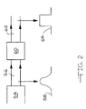
- a generic beam homogenizer is shown in FIG. 2.
- a full power laser beam 56 may have a Gaussian distribution 58 (TEM 00 ), donut mode (TEM 01 ), or some higher order mode spatial power distribution.
- the function of a beam homogenizer 60 is to transform beam 56 into a beam 62 having a uniform energy intensity distribution across the spatial extent of the beam. This is a square or top hat distribution 64.
- One way to achieve this is to focus the beam into a step-index optical fiber.
- FIG. 3 illustrates a raw collimated beam 56 from a laser 54 is focused by a lens 66 into the end of a step-index optical fiber 68.
- another lens 72 is placed to re-collimate the beam.
- free electron raw laser beam 56 is split by beam splitters into sub-beams of reasonable power, e.g., no more than 10 KW each, then each sub-beam could be focused into a fiber to achieve the uniform spatial power distribution.
- the free electron laser can be tuned over a fairly large wavelength range.
- a reasonably priced fiber with low attenuation is only practical if the laser wavelength is in the near UV, visible, and near IR part of the spectrum. 16.
- the radiation has a photon wavelength in the ultraviolet range.
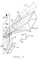
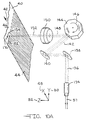
- FIG. 4A A preferred method of homogenizing a laser radiation beam utilizing a line projection is illustrated in FIG. 4A.
- This optical system uses a specially designed linear diverging lens 74 that has the appearance of a prism with a relatively sharp radius at the apex.
- a lens is disclosed in US patent 4,826,299. It expands the laser beam 20 in one direction only so that a wedge of laser radiation 76 is formed which has a uniform intensity distribution along its transverse or y-direction 50.
- Line length 86 increases linearly in the y-direction as the radiation diverges away from the lens in a z-direction 52.
- An intensity distribution 82 along the line length is not perfectly uniform but has some variation 84 as illustrated in FIG. 4B.
- An additional plano-convex cylindrical lens 78 is illuminated by the projected laser line 80 so that the laser beam is sharply focused into line 38 on the surface of the oxide layer to be removed.
- the design of diverging lens 74 must include the incident diameter of the laser beam.
- the line projector lens must be made from the appropriate material based on the wavelength of the laser radiation that will pass through it. This is to avoid absorption of the laser radiation as it is refracted by the projector lens. For example, if the free electron laser wavelength was tuned to be at 1 micron in the near infrared part of the spectrum, then fused silica or BK7 can be used to construct the laser line projector. This material must also be anti-reflection coated for the laser wavelength.
- Final focusing lens 78 will also be made from the same material and anti reflection coated to minimize absorptive and reflective laser losses respectively.
- the width of the focused laser line is controlled by the focal length of this final cylindrical lens 78.
- the length of the laser line is determined by how far the line projector lens 74 is from the final oxide covered metal surface.
- Final cylindrical focusing lens 78 can be replaced by a combination of a long rectangular flat mirror 168 for redirecting the line of laser radiation and a final cylindrical concave focusing mirror 170 such as shown in FIG. 10B.
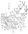
- FIG. 5 illustrates a pair of sub-beams covering the full width of metal strip 40 with each beam covering one-half of the strip width. It will be understood this concept can be extended to include any number of sub-beams. For example, if the beam is divided into ten sub-beams, each sub-beam would descale one-tenth the width of the metal strip.
- the embodiment of FIG. 5 includes a sealed interaction chamber 90 having a sealed entry for receiving strip 40, a sealed exit 92 and a pair of sealed windows 93 which allow beams 36 to pass into the chamber.
- Chamber 90 also includes an exhaust duct 94 for carrying removed scale debris to a filter unit 96, a delivery duct 98, a blower 100 for circulating a non-oxidizing gas through a gas return duct 102 into a return vent 104 within chamber 90. The gas is recirculated by blower 100 to pick up the scale debris which is deposited in a filter and returned to chamber 90.
- Each sub-beam 20 will be passed through one of the anamorphic upcollimators (lenses 22, 26, 30) described above in FIG. 1 or by mirrors described in detail in FIG. 9 and then focused by cylindrical lens 34 (or a concave mirror).
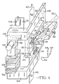
- FIGS. 6-8 illustrate more detailed views of a reaction zone at and adjacent to the point of incidence of laser beam 36 and metal surface 44 within chamber 90.
- Chamber 90 contains a non-oxidizing gas 108, such as helium or argon, supplied from a reservoir 110. This inert gas medium is used to protect the reaction zone and to transport vaporized oxide particles 118 away from the interaction chamber.
- Incident beam 36 is shown as a converging rectangular wave front focused onto moving metal strip surface 44.
- beam 36 is incident at some non-perpendicular, i.e., acute, angle onto strip surface 44.
- acute it will be understood to mean a preferred angle in the range of 10-75° as measured from the normal to the metal surface.
- a more preferred range is 25-60° and a most preferred angle is 30°. It is known that a plasma plume 112 created by the vaporized debris has its highest intensity in a direction perpendicular to the strip surface. By orienting the direction of the incident focused radiation away from a direction normal to the surface, it is believed that there will be less absorption of incoming incident beam 36 by created plasma 112. This will yield a higher efficiency in removing the oxide layer. Above plume 112 and just beyond the focusing rectangular wave front of beam 36 is mounted a long slot-like gas nozzle 114 for directing inert gas 108 onto created plasma 112.
- An important feature of this invention is to surround the plasma created plume as well as clean metal surface 46 with the non-oxidizing atmosphere to prevent reoxidation of cleaned metal surface 46.
- the ambient atmosphere i.e., oxygen
- Nozzle 114 extends the full length of focused line 38.
- An exhaust vent 116 in duct 94 is placed on the side of the chamber opposite from where incident beam 36 enters and withdraws the inert gas ladened with debris oxide particles 118 into exhaust duct 94.
- Duct 94 and gas nozzle 114 preferably are mounted on the entrance side of the chamber, i.e., adjacent the dirty strip surface 44. This minimizes the amount of debris that might otherwise settle back onto the cleaned metal strip from recontaminating freshly descaled surface 46. Instead, debris particles 118 would fall onto untreated surface 44 and pass back into incident beam 36 where it will be vaporized again. Debris oxide (scale) particles 118 are drawn toward the entry side of the chamber as indicated by the direction of arrow 180 to be deposited into a filter 106 positioned within filter unit 96 that removes the micron size debris particles. This would be especially true if strip 40 is traveling in a vertical direction so that gravity will tend to cause debris particles to fall away from the strip toward exhaust vent 116.
- Filter unit 96 may also include a vibratory mechanism so that the debris particles can be deposited in a collection container (not shown) located below the filter.
- Inert gas 108 is drawn through filter 106 and recirculated by blower 100 and re-enters vacuum chamber 90 through nozzle 114 to pick up more debris 118.
- Gas reservoir 110 periodically injects fresh inert gas 108 into return duct 102 to replenish any lost gas.
- a pressure gauge 120 in the nozzle monitors gas pressure and is used to control a solenoid valve 122 on the gas reservoir. It shows the flow pattern of inert gas 108 and debris particles 118 that are picked up by this flow and how the particles are transported to exhaust vent 116.
- the same nozzle and exhaust system can be used with the scanned focused spot system such as described in FIG. 10A & 10B. In this case, the focused line is now the scan field width that the focused spot is scanned across.
- FIG. 8 illustrates the importance of preventing ambient atmosphere from entering into chamber 90.
- a protective atmosphere 108 within chamber 90.
- lens 34 is mounted within window 93 thereby forming a seal.
- An entry 91 (FIG. 6) for receiving strip 40 and exit 92 both preferably are sealed with a flexible material 178 such as polypropylene.
- gas nozzle 114 By orienting gas nozzle 114 toward metal surface 44 at an angle with a gas velocity component toward exhaust vent 116, the inert gas ladened with debris oxide particles 118 is directed toward exhaust duct 94.
- Positioning duct 94 and gas nozzle 114 on the entrance side of the chamber above dirty strip surface 44 will prevent any debris that might otherwise settle back onto the cleaned metal strip from recontaminating freshly descaled surface 46.
- the width of focused 38 line in the metal movement direction 42 will be determined by the focal length of final focusing lens 34, the degree of upcollimation achieved, and by the divergence of beam 20 incident on first lens 22 of the anamorphic upcollimator. It would be possible to control this width of focused line 38 over the range from approximately 0.1 mm to many centimeters. The actual value will depend on the length of the focused line and the energy per pulse. For example, if a 100 KW raw beam 14 from laser 54 is split into 10 sub-beams of 10 KW each and it is desired to descale a 1 meter wide metal strip, then each of the 10 focused lines will be 10 cm long and will be focused to a width of approximately 2 mm for each.
- each pulse in each of the 10 KW sub-beams will have an energy of 333 microjoules and will have a focused surface power density of approximately 83 MW/cm 2 .
- An important feature of this invention is that the surface power density (watts/cm 2 ) be sufficiently high to cause vaporization of the oxide on the metal strip. This requirement is fundamental for this invention in determining the length and width of the focused line so that the laser energy per unit time per pulse delivered over this line meets this criterion of giving rise to a surface power density of at least 5 MW/cm 2 .
- the length of the focused line transverse to the direction of metal travel direction 42 can be as small as 1 mm to as wide as 2 m, and the focused line width can be from 0.1 mm to 10 cm so long as the above surface power density constraints are maintained.
- the length of the laser line with a 100 KW average power laser beam would be 1 m extending completely across the full width of the metal strip and the width of focused line 38 being 2 mm.
- a pulse energy of 3.33 millijoules and a 2 picosecond pulse width this gives the same surface power density per pulse of 83 MW/cm 2 mentioned above that is obtained for each of the 10 cm long sections that is focused by a refractive lens system.
- the same full metal surface descale capability can be obtained by a single optical system focusing the entire 100 KW, or 10 subsystems each focusing 10 KW, or even 100 subsystems each focusing 1 KW.
- the details as to which optical system is used depends upon other issues such as the comparative cost and availability of the optical components.
- the oxide film will become vaporized and removed from the entire surface area of the metal strip forming clean metal surface 46 substantially free of any oxide without any other mechanical or chemical assistance.
- a pre-treatment such as shot blasting or roller leveling to crack or loosen the scale would not be required prior to the laser treatment and little, if any, cursory post-treatment such as an immersion acid pickling would be necessary for dissolving any remaining amounts of the scale after the laser treatment.
- the descaling process of this invention would have significant environmental advantages because disposal of toxic pickle liquors would no longer be required.
- Metal strip surface 44 moves under focused line 38 at a rate of speed that is consistent with the pulse repetition rate and pulse energy needed to remove the oxide thickness completely to the base metal. Since the metal strip is moving continuously in a vertical direction at line speeds of at least 10 m/min, preferably at least 30 m/min and possibly as much as a few hundred meters per minute, the high pulse repetition rate, e.g., 30 MHz, means multiple pulses will strike the same location. This is necessary since one pulse alone does not contain enough energy to completely remove the scale layer. Each pulse removes some number of molecular layers so that a large number of pulses at the same location is required to completely remove the scale layer down to the base metal.
- the lens (or mirror) optical combination is large enough to cover the width of the widest metal strip, e.g., about two meters, likely to require descaling, there are additional considerations suggesting multiple combinations of lenses or mirrors may be a better method.
- a mirror optical system it is possible to cover about a 1 m wide section with a single set of mirrors.
- a mirror optical element typically is able to accept a higher power density on the reflecting surface than a refractive element. Refractive elements have some degree of radiation absorption causing heating to an elevated temperature. When the average power is higher than 10 KW, heating of the optical element can be a significant effect depending on the beam diameter.
- the invention also can utilize a combination of flat, convex, and concave mirrors to focus the laser radiation into a transverse line.
- FIG. 9 illustrates another embodiment of the invention using a combination of convex, flat, and concave mirrors used to focus the laser radiation into a line.
- Incident raw laser beam 20 strikes the surface of a convex mirror 124 that diverges the beam in both x-direction 48 and y-direction 50 into divergent beam 24.
- Divergent beam 24 then is intercepted by a cylindrical concave mirror 126 which acts to collimate the beam in the x-direction into collimated beam 28.
- beam 28 continues to expand in the y-direction until it strikes a cylindrical concave mirror 128 which acts to collimate the beam in the y-direction into beam 32.
- Collimated beam 32 now has a rectangular shape whose cross sectional dimensions are controlled by the focal lengths and spacings of mirrors 124, 126, and 128.
- the length in the y-direction of this rectangular cross section is determined by the desired width of metal strip 40 treated by this optical system. If there are to be multiple optical systems to cover the full width of the strip surface, then the length of the optical system will only be a fraction of the full width.
- Beam 32 is then reflected by a rectangular flat mirror 130 to a long final focusing cylindrical concave mirror 132 having the same length as the desired final focused line 38.
- a scanning focused spot optical beam delivery method can also be used to remove the oxide layer (scale).
- a refractive based optical system for this embodiment is illustrated in FIG. 10A.
- Full power laser beam 56 can be split into sub-beams 57 of smaller more manageable power with each sub-beam being scanned over some fraction of the full width of the metal strip.
- One beam 57 then is passed through an upcollimator 134 which increases the beam diameter and decreases the beam divergence. (If a large diameter beam with low divergence is produced by the laser, it may be necessary to down-collimate the beam to reduce the beam diameter to a more manageable size.
- a beam diameter from a 100 KW FEL laser may be many centimeters in diameter with a diffraction limited divergence so that down collimation may be necessary.
- Upcollimated (or down-collimated) beam 136 is passed through a pair of mirrors 138 and 140 that direct a beam 142 at the proper angle into a scanning mechanism 144 that may be a rotating polygon or oscillating mirror 146.
- a beam 148 then is passed though a flat field focusing lens 150 focusing collimated beam 148 to a desired spot size 154 onto the surface of metal strip 40 to be descaled.
- An advantage of the scanned focused spot system is that it does not require the intensity distribution across the incoming laser beam to be spatially uniform. That is, homogenizer 60 would not be required.
- the scanning mechanism allows the focused spot to be scanned transversely across oxide covered surface 44 so that the attached scale layer is removed by one or more pulses of laser radiation at each point along scan line 182 as metal strip 40 continuously passes through the transversely scanning focused laser spot.
- a disadvantage over the projected and focused laser line illustrated in FIG. 4A is that it adds more optical surfaces for additional loss of laser energy and it has a mechanical moving element.
- flat field focusing lens 150 of FIG. 10A could be replaced with a pre-scanning focusing lens positioned ahead of oscillating mirror 146.
- the pre-scanning focusing lens would move back and forth in the beam propagation direction in synchronization with the scanning speed of the mirror to keep the spot focused on the flat metal surface.
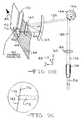
- FIG. 10B illustrates yet another embodiment of the invention for an optical scanning spot system that uses mirrors with a focusing lens to provide a telecentric scanning system to maintain a uniform spot size over the scan field width.
- Laser beam 136 is incident on a lens 156 positioned ahead of rotating scanning polygon 146 for redirecting a beam 158.
- a converging beam 159 then is directed toward a long rectangular flat mirror 160 extending for a large portion of the desired scan field.
- Mirror 160 redirects a scanned beam 162 to a curved parabolic mirror 164 extending the full width of the scan field. This curved mirror redirects a converging beam 166 so that it is incident on the surface at the same angle regardless of where across the scan field the beam is focused.
- the beam is focused to the same spot size all along the scan field length.
- This system has the advantage over the refractive system illustrated in FIG. 10A in that most of the optical elements are mirrors that do not have the absorptive losses of refractive elements. This is advantageous because of the high powers necessary for an economic full production laser descaling system.
- a long flat rectangular mirror 168 can be added to direct the focusing radiation to a long cylindrical concave focusing mirror 170 for converging the radiation into a convergent beam 172 to provide additional compression of the focused spot in strip travel direction 42.
- Full cross-width convergent cylindrical lens 34 could be used in place of mirrors 168 and 170 to focus the beam into a smaller down web dimension. This will result in a focused elliptical spot 174 with the long direction of the focused spot in scanning direction 176 as illustrated in greater detail in FIG. 10C.
- a projected laser line system such as that illustrated in FIG. 4A will be used to focus the laser radiation into a line.
- the line speed necessary to remove this 5 micron thick layer one requires an aluminum strip with the oxide layer can only move the width of the focused laser line, i.e., 2 mm, in the time it takes to deliver the full 117,720 pulses.
- a full 1 m wide aluminum strip could have a 5 micron thick oxide layer removed from one side at a rate of 30.6 m/min. It should be pointed out the oxide removal rate may be higher due to other mechanisms of scale removal that may be operating because of the short pulse width and high surface power density. However, by this calculation based simply on a thermal vaporization mechanism, a 200 KW FEL laser would be required to descale both sides of this one meter wide aluminum strip at 30.6 m/min.
Landscapes
- Physics & Mathematics (AREA)
- Optics & Photonics (AREA)
- Engineering & Computer Science (AREA)
- Plasma & Fusion (AREA)
- Mechanical Engineering (AREA)
- Laser Beam Processing (AREA)
- Cleaning And De-Greasing Of Metallic Materials By Chemical Methods (AREA)
- Electrical Discharge Machining, Electrochemical Machining, And Combined Machining (AREA)
- Commercial Cooking Devices (AREA)
Claims (14)
- Verfahren zum Entfernen von Oxid von einer Metalloberfläche mit den Schritten:Verwenden eines Leitungselektronen-Lasers zur Erzeugung elektromagnetischer Strahlung (20) mit einer sehr kurzen Pulsweite von weniger als 1 ns, einer sehr hohen Pulswiederholungsrate von mindestens 1 kHz und einer sehr hohen durchschnittlichen Leistung von mindestens 1 kW,Fokussieren der Strahlung durch mindestens ein optisches Element (22, 74) zu einem einfallenden Strahl (36) mit einer Oberflächenleistungsdichte von mindestens ungefähr 5 MW/cm2 an einem Kontaktpunkt (38) mit der Metalloberfläche (44) undFühren des fokussierten Strahls (36, 76) quer und vollständig über die mit dem Oxid bedeckte Metalloberfläche (44) zur Entfernung des Oxids durch Verdampfen durch die Wechselwirkung eines oder mehrerer Laserpulse, um dadurch eine oxidfreie Oberfläche (46) zu erzeugen.
- Verfahren nach Anspruch 1, dadurch gekennzeichnet, dass die der Oberfläche (44) der Oxidschicht zugeführte Oberflächenleistungsdichte pro Laserpuls mindestens 10 MW/cm2 beträgt.
- Verfahren nach Anspruch 1 oder 2, dadurch gekennzeichnet, dass das optische Element eine Kombination aus mindestens einer Linse (156) und mindestens einem Spiegel (160) umfasst.
- Verfahren nach einem der Ansprüche 1 bis 3, dadurch gekennzeichnet, dass das optische Element Mittel zur Teilung des Strahls (20) in eine Mehrzahl von fokussierten Nebenstrahlen (20) umfasst, wobei jeder Nebenstrahl eine Leistung hat, die kleiner ist als die des Strahls, welcher von dem Laser ausgeht.
- Verfahren nach einem der Ansprüche 1 bis 4, dadurch gekennzeichnet, dass der Strahl (20) zu mindestens einer Linie (38) mit einer gleichmäßigen Leistungsverteilung fokussiert wird, die sich quer über die gesamte Breite der Metalloberfläche (44) erstreckt.
- Verfahren nach einem der vorangehenden Ansprüche, gekennzeichnet durch die zusätzlichen Schritte: Schützen des Kontaktpunkts (38) und Wegspülen der Oxidtrümmer mit einem nicht oxidierenden Gas.
- Verfahren nach Anspruch 3, dadurch gekennzeichnet, dass die Kombination aus einer Linse und einem Spiegel ein erstes optisches Element, das eine Kollimatorlinse (134) ist, ein zweites optisches Element, das einen Richtspiegel (138) zur Orientierung des ausgerichteten Strahls (136) und ein Mittel (144) zum Abtasten des gerichteten Strahls umfasst.
- Verfahren nach Anspruch 7, dadurch gekennzeichnet, dass die optischen Element ferner eine Flachfeld-Abtastlinse (150) umfassen und das Abtastmittel (144) einen Drehspiegel (146) zum wiederholten Abtasten des gerichteten Strahls über eine Eintrittspupille der Flachfeldlinse (150) umfasst.
- Verfahren nach Anspruch 3, dadurch gekennzeichnet, dass die Kombination aus einer Linse und einem Spiegel ein telezentrisches System ist mit einem Drehspiegel (146) zum Abtasten des Strahls (159), einem Parabolspiegel (164) zum Wiederausrichten des abgetasteten Strahls im gleichen Winkel zu der Oberfläche, ungeachtet dessen, wo der Strahl über das Abtastfeld auf die Oberfläche (44) fokussiert ist.
- Verfahren zum Entfernen von Oxid von einer Oberfläche eines Metallbandes mit den Schritten:Verwenden eines Leitungselektronen-Lasers zur Erzeugung elektromagnetischer Strahlung (20) mit einer Pulsweite von weniger als 1 ps, einer Pulswiederholungsrate von mindestens 10 MHz und einer durchschnittlichen Leistung, die größer ist als 10 kW,Fokussieren der Laserstrahlung durch mindestens ein optisches Element (22, 74) zu einem einfallenden Strahl (36, 76) mit einer Oberflächenleistungsdichte von mindestens ungefähr 10 MW/cm2 an einem Kontaktpunkt (38) mit der Oberfläche des Bandes (44), wobeidas optische Element (22, 74) Mittel zur Homogenisierung der Strahlung und mindestens eine lange zylindrische konvexe Linse oder einen langen zylindrischen konkaven Spiegel zum Fokussieren des Strahls zu mindestens einer geraden Linie umfasst,Führen des Bandes (40) durch die fokussierte Linie (38) der Strahlung quer und vollständig über die mit dem Oxid bedeckte Oberfläche (44) zur Entfernung des Oxids durch Verdampfen durch die Wechselwirkung eines oder mehrerer räumlich verlängerter Laserpulse, um dadurch eine oxidfreie Oberfläche (46) zu erzeugen.
- Vorrichtung zum Entfernen von Oxid von einer Oberfläche eines Metallbandes (40) mit:einem Leitungselektronen-Lasers zur Erzeugung elektromagnetischer Strahlung (20) mit einer sehr kurzen Pulsweite von weniger als 1 ns, einer sehr hohen Pulswiederholungsrate von mindestens 1 kHz und einer sehr hohen durchschnittlichen Leistung von mindestens 1 kW,mindestens einem optischen Element (22, 74) zum Fokussieren der Laserstrahlung zu einem einfallenden Strahl (36; 76) mit einer Oberflächenleistungsdichte von mindestens ungefähr 5 MW/cm2 an einem Kontaktpunkt mit dem Metallband (40), undeiner abgedichteten Wechselwirkungskammer (90) zum Entfernen des Oxids von dem Metallband (40), wobeidiese Kammer (90) ein nicht oxidierendes Gas und einen geschlitzten Einlass zur Aufnahme eines sich bewegenden Metallbandes (40) mit einer mit einem Oxid bedeckten Oberfläche (44), einen geschlitzten Auslass zur Durchführung des Metallbandes (40), von dessen Oberfläche das Oxid entfernt wurde, und mindestens ein langgestrecktes Fenster (93) zur Aufnahme der Strahlung in der Kammer (90) umfasst, wodurch die Strahlung zur Entfernung des Oxids durch Verdampfen quer und vollständig über die mit dem Oxid bedeckte Oberfläche (44) geführt wird.
- Vorrichtung nach Anspruch 11, dadurch gekennzeichnet, dass das optische Element (34) eine in dem Fenster (93) angeordnete Linse (34) ist.
- Vorrichtung nach Anspruch 11, dadurch gekennzeichnet, dass das optische Element (34) Mittel zur Teilung des Strahls (20) in eine Mehrzahl von fokussierten Nebenstrahlen (20) umfasst und die Kammer (90) eine entsprechende Anzahl von Fenstern (93) umfasst, wobei jedes Fenster zur Aufnahme eines der Nebenstrahlen dient.
- Vorrichtung nach einem der Ansprüche 11 bis 13, dadurch gekennzeichnet, dass sie so aufgebaut ist, dass der einfallende Strahl (36, 76) an einem Kontaktpunkt mit dem Metallband (40) eine Oberflächenleistungsdichte von mindestens ungefähr 10 MW/cm2 haben kann.
Priority Applications (12)
| Application Number | Priority Date | Filing Date | Title |
|---|---|---|---|
| US08/695,930 US5736709A (en) | 1996-08-12 | 1996-08-12 | Descaling metal with a laser having a very short pulse width and high average power |
| US08/972,350 US5948172A (en) | 1996-08-12 | 1997-11-17 | Descaling metal with a laser having a very short pulse width and high average power |
| CA002225507A CA2225507A1 (en) | 1996-08-12 | 1997-12-22 | Descaling metal with a laser having a very short pulse width and high average power |
| AU49249/97A AU4924997A (en) | 1996-08-12 | 1997-12-23 | Descaling metal with a laser having a very short pulse width and high average power |
| ZA9711591A ZA9711591B (en) | 1996-08-12 | 1997-12-23 | Descaling metal with a laser having a very short pulse width and high average power. |
| ES97122937T ES2172740T3 (es) | 1996-08-12 | 1997-12-29 | Descascarillado de metales con laser de ancho de pulso corto y potencia promedio alta. |
| AT97122937T ATE215417T1 (de) | 1996-08-12 | 1997-12-29 | Entzundern von metallen durch einen laser mit sehr kurzer pulsbreite und hoher durchschnittsleistung |
| EP97122937A EP0927595B1 (de) | 1996-08-12 | 1997-12-29 | Entzundern von Metallen durch einen Laser mit sehr kurzer Pulsbreite und hoher Durchschnittsleistung |
| DE69711652T DE69711652T2 (de) | 1996-08-12 | 1997-12-29 | Entzundern von Metallen durch einen Laser mit sehr kurzer Pulsbreite und hoher Durchschnittsleistung |
| BR9800348-8A BR9800348A (pt) | 1996-08-12 | 1998-01-16 | Remoção de crosta de com laser tendo amplititude de pulso muito curta e uma potência média alta |
| CN98106412A CN1224644A (zh) | 1996-08-12 | 1998-01-27 | 用脉冲宽度很短和平均功率高的激光使金属去除氧化皮 |
| JP10068782A JPH11262449A (ja) | 1996-08-12 | 1998-03-18 | 業務用炊飯装置 |
Applications Claiming Priority (8)
| Application Number | Priority Date | Filing Date | Title |
|---|---|---|---|
| US08/695,930 US5736709A (en) | 1996-08-12 | 1996-08-12 | Descaling metal with a laser having a very short pulse width and high average power |
| CA002225507A CA2225507A1 (en) | 1996-08-12 | 1997-12-22 | Descaling metal with a laser having a very short pulse width and high average power |
| AU49249/97A AU4924997A (en) | 1996-08-12 | 1997-12-23 | Descaling metal with a laser having a very short pulse width and high average power |
| ZA9711591A ZA9711591B (en) | 1996-08-12 | 1997-12-23 | Descaling metal with a laser having a very short pulse width and high average power. |
| EP97122937A EP0927595B1 (de) | 1996-08-12 | 1997-12-29 | Entzundern von Metallen durch einen Laser mit sehr kurzer Pulsbreite und hoher Durchschnittsleistung |
| BR9800348-8A BR9800348A (pt) | 1996-08-12 | 1998-01-16 | Remoção de crosta de com laser tendo amplititude de pulso muito curta e uma potência média alta |
| CN98106412A CN1224644A (zh) | 1996-08-12 | 1998-01-27 | 用脉冲宽度很短和平均功率高的激光使金属去除氧化皮 |
| JP10068782A JPH11262449A (ja) | 1996-08-12 | 1998-03-18 | 業務用炊飯装置 |
Publications (2)
| Publication Number | Publication Date |
|---|---|
| EP0927595A1 EP0927595A1 (de) | 1999-07-07 |
| EP0927595B1 true EP0927595B1 (de) | 2002-04-03 |
Family
ID=31892410
Family Applications (1)
| Application Number | Title | Priority Date | Filing Date |
|---|---|---|---|
| EP97122937A Expired - Lifetime EP0927595B1 (de) | 1996-08-12 | 1997-12-29 | Entzundern von Metallen durch einen Laser mit sehr kurzer Pulsbreite und hoher Durchschnittsleistung |
Country Status (10)
| Country | Link |
|---|---|
| US (2) | US5736709A (de) |
| EP (1) | EP0927595B1 (de) |
| JP (1) | JPH11262449A (de) |
| CN (1) | CN1224644A (de) |
| AT (1) | ATE215417T1 (de) |
| AU (1) | AU4924997A (de) |
| BR (1) | BR9800348A (de) |
| CA (1) | CA2225507A1 (de) |
| DE (1) | DE69711652T2 (de) |
| ES (1) | ES2172740T3 (de) |
Cited By (2)
| Publication number | Priority date | Publication date | Assignee | Title |
|---|---|---|---|---|
| DE102007020748A1 (de) * | 2007-05-03 | 2008-11-13 | Clean-Lasersysteme Gmbh | Vorrichtung und Verfahren zum Bearbeiten einer Oberfläche eines Werkstücks mittels Laserstrahlung |
| EP2991126A1 (de) | 2014-08-25 | 2016-03-02 | Theva Dünnschichttechnik GmbH | Verfahren und Vorrichtung zum Herstellen eines Hochtemperatur-Supraleiters |
Families Citing this family (190)
| Publication number | Priority date | Publication date | Assignee | Title |
|---|---|---|---|---|
| US6189414B1 (en) * | 1995-12-19 | 2001-02-20 | Yoshizawa Industry Inc. | Counter plate and cutting die for die cutting machine |
| US5720894A (en) * | 1996-01-11 | 1998-02-24 | The Regents Of The University Of California | Ultrashort pulse high repetition rate laser system for biological tissue processing |
| US6555449B1 (en) * | 1996-05-28 | 2003-04-29 | Trustees Of Columbia University In The City Of New York | Methods for producing uniform large-grained and grain boundary location manipulated polycrystalline thin film semiconductors using sequential lateral solidfication |
| US5736709A (en) * | 1996-08-12 | 1998-04-07 | Armco Inc. | Descaling metal with a laser having a very short pulse width and high average power |
| US6303901B1 (en) * | 1997-05-20 | 2001-10-16 | The Regents Of The University Of California | Method to reduce damage to backing plate |
| US6300594B1 (en) * | 1998-02-19 | 2001-10-09 | Ricoh Microelectronics Company, Ltd. | Method and apparatus for machining an electrically conductive film |
| ES2143962B1 (es) * | 1998-07-14 | 2000-12-01 | Consejo Superior Investigacion | Procedimiento de limpieza de superficies metalicas con laser. |
| US6555781B2 (en) * | 1999-05-10 | 2003-04-29 | Nanyang Technological University | Ultrashort pulsed laser micromachining/submicromachining using an acoustooptic scanning device with dispersion compensation |
| BE1012686A3 (fr) * | 1999-05-26 | 2001-02-06 | Wallonia Space Logistics En Ab | Procede et dispositif de decapage du bois. |
| US6326861B1 (en) * | 1999-07-16 | 2001-12-04 | Feltech Corporation | Method for generating a train of fast electrical pulses and application to the acceleration of particles |
| US6472295B1 (en) | 1999-08-27 | 2002-10-29 | Jmar Research, Inc. | Method and apparatus for laser ablation of a target material |
| US7112545B1 (en) | 1999-09-10 | 2006-09-26 | The Board Of Trustees Of The University Of Arkansas | Passivation of material using ultra-fast pulsed laser |
| AU7366800A (en) * | 1999-09-10 | 2001-04-10 | Board Of Trustees Of The University Of Arkansas, The | Passivation of material using ultra-fast pulsed laser |
| JP4514861B2 (ja) * | 1999-11-29 | 2010-07-28 | 株式会社半導体エネルギー研究所 | レーザ照射装置およびレーザ照射方法および半導体装置の作製方法 |
| US6861364B1 (en) | 1999-11-30 | 2005-03-01 | Canon Kabushiki Kaisha | Laser etching method and apparatus therefor |
| US6627846B1 (en) * | 1999-12-16 | 2003-09-30 | Oramir Semiconductor Equipment Ltd. | Laser-driven cleaning using reactive gases |
| US7723642B2 (en) * | 1999-12-28 | 2010-05-25 | Gsi Group Corporation | Laser-based system for memory link processing with picosecond lasers |
| US7500298B2 (en) * | 2000-02-14 | 2009-03-10 | Sadler Love & Associates, Inc. | Blast head for loosening or removing scale on a metal surface |
| WO2001060568A1 (en) | 2000-02-14 | 2001-08-23 | Sadler Love & Associates, Inc. | Method and apparatus for the descaling of metal |
| US20050198794A1 (en) * | 2000-02-14 | 2005-09-15 | Sadler Love & Associates, Inc. | Apparatus for the descaling of metal |
| US6830993B1 (en) | 2000-03-21 | 2004-12-14 | The Trustees Of Columbia University In The City Of New York | Surface planarization of thin silicon films during and after processing by the sequential lateral solidification method |
| US6560248B1 (en) | 2000-06-08 | 2003-05-06 | Mania Barco Nv | System, method and article of manufacture for improved laser direct imaging a printed circuit board utilizing a mode locked laser and scophony operation |
| JP4659300B2 (ja) * | 2000-09-13 | 2011-03-30 | 浜松ホトニクス株式会社 | レーザ加工方法及び半導体チップの製造方法 |
| WO2002025785A2 (en) * | 2000-09-22 | 2002-03-28 | Vermont Photonics | Apparatuses and methods for generating coherent electromagnetic laser radiation |
| CA2389607A1 (en) | 2000-10-10 | 2002-04-18 | The Trustees Of Columbia University | Method and apparatus for processing thin metal layers |
| AU2002255875A1 (en) * | 2001-03-23 | 2002-10-08 | Vermont Photonics | Applying far infrared radiation to biological matter |
| US7009140B2 (en) * | 2001-04-18 | 2006-03-07 | Cymer, Inc. | Laser thin film poly-silicon annealing optical system |
| DE10125206B4 (de) * | 2001-05-14 | 2005-03-10 | Forschungsverbund Berlin Ev | Verfahren zur direkten Mikrostrukturierung von Materialien |
| GB0127410D0 (en) | 2001-11-15 | 2002-01-09 | Renishaw Plc | Laser substrate treatment |
| GB0201101D0 (en) * | 2002-01-18 | 2002-03-06 | Renishaw Plc | Laser marking |
| US7276127B2 (en) * | 2002-02-01 | 2007-10-02 | Metastable Instruments, Inc. | Method and apparatus for cleaning with internally reflected electromagnetic radiation |
| CN100355032C (zh) | 2002-03-12 | 2007-12-12 | 浜松光子学株式会社 | 基板的分割方法 |
| FR2837733B1 (fr) * | 2002-03-28 | 2005-01-14 | Centre Nat Etd Spatiales | Procede et dispositif d'ablation d'une couche de couverture recouvrant une surface a mettre a nu |
| JP3559827B2 (ja) * | 2002-05-24 | 2004-09-02 | 独立行政法人理化学研究所 | 透明材料内部の処理方法およびその装置 |
| US7622370B2 (en) | 2002-08-19 | 2009-11-24 | The Trustees Of Columbia University In The City Of New York | Process and system for laser crystallization processing of film regions on a substrate to minimize edge areas, and a structure of such film regions |
| CN1757093A (zh) * | 2002-08-19 | 2006-04-05 | 纽约市哥伦比亚大学托管会 | 具有多种照射图形的单步半导体处理系统和方法 |
| GB0222342D0 (en) * | 2002-09-26 | 2002-11-06 | British Nuclear Fuels Plc | Surface treatment of concrete |
| US6759627B2 (en) * | 2002-10-17 | 2004-07-06 | Chris A. Kilburn | Method and apparatus for cleaning generator and turbine components |
| US20050035096A1 (en) * | 2002-10-17 | 2005-02-17 | Kilburn Chris A. | Method and apparatus for cleaning generator, turbine and boiler components |
| JP5164378B2 (ja) * | 2003-02-19 | 2013-03-21 | ザ トラスティーズ オブ コロンビア ユニヴァーシティ イン ザ シティ オブ ニューヨーク | 逐次的横方向結晶化技術を用いて結晶化させた複数の半導体薄膜フィルムを処理するシステム及びプロセス |
| US7361171B2 (en) | 2003-05-20 | 2008-04-22 | Raydiance, Inc. | Man-portable optical ablation system |
| US20040231682A1 (en) * | 2003-05-20 | 2004-11-25 | Richard Stoltz | Scanned small spot ablation with a high-rep-rate |
| US8173929B1 (en) | 2003-08-11 | 2012-05-08 | Raydiance, Inc. | Methods and systems for trimming circuits |
| US9022037B2 (en) | 2003-08-11 | 2015-05-05 | Raydiance, Inc. | Laser ablation method and apparatus having a feedback loop and control unit |
| US8921733B2 (en) | 2003-08-11 | 2014-12-30 | Raydiance, Inc. | Methods and systems for trimming circuits |
| TWI351713B (en) | 2003-09-16 | 2011-11-01 | Univ Columbia | Method and system for providing a single-scan, con |
| WO2005029546A2 (en) * | 2003-09-16 | 2005-03-31 | The Trustees Of Columbia University In The City Of New York | Method and system for providing a continuous motion sequential lateral solidification for reducing or eliminating artifacts, and a mask for facilitating such artifact reduction/elimination |
| TWI359441B (en) | 2003-09-16 | 2012-03-01 | Univ Columbia | Processes and systems for laser crystallization pr |
| WO2005029547A2 (en) | 2003-09-16 | 2005-03-31 | The Trustees Of Columbia University In The City Of New York | Enhancing the width of polycrystalline grains with mask |
| US20050115939A1 (en) * | 2003-12-01 | 2005-06-02 | Laser Fare, Inc. | Method and apparatus for drilling a large number of precision holes with a laser |
| EP1598121A3 (de) * | 2004-05-18 | 2007-02-14 | Airbus Deutschland GmbH | Lasergestütztes Entschichtungsverfahren |
| DE102004027229B4 (de) * | 2004-06-03 | 2007-01-04 | Fraunhofer-Gesellschaft zur Förderung der angewandten Forschung e.V. | Verfahren zum Schweißen von Werkstücken aus Aluminium oder einer Aluminiumlegierung |
| JP2006061966A (ja) * | 2004-08-30 | 2006-03-09 | Japan Atom Energy Res Inst | fs(フェムト秒)域極短パルスkW級高平均出力レーザーを用いて鋼鉄及びステンレス鋼を含む合金鋼鉄の冷間加工に伴う応力腐食割れを防止する方法 |
| US20060189091A1 (en) * | 2004-11-11 | 2006-08-24 | Bo Gu | Method and system for laser hard marking |
| US7526003B2 (en) * | 2004-12-08 | 2009-04-28 | Polaronyx, Inc. | Nonlinear polarization pulse shaping mode locked fiber laser at one micron |
| US7211763B2 (en) * | 2004-12-22 | 2007-05-01 | General Electric Company | Photon energy material processing using liquid core waveguide and a computer program for controlling the same |
| US7477666B2 (en) * | 2005-04-06 | 2009-01-13 | Polar Onyx, Inc. | All fiber based short pulse amplification at one micron |
| FR2887161B1 (fr) * | 2005-06-20 | 2007-09-07 | Commissariat Energie Atomique | Procede et dispositif d'ablation laser d'une couche superficielle d'une paroi, telle q'un revetement de peinture dans une installation nucleaire |
| CH698238B1 (de) * | 2005-07-07 | 2009-06-30 | Main Man Inspiration Ag | Vorrichtung zur kontinuierlichen Oberflächenreinigung einer drehbeweglichen Giessrolle einer Bandgiessmaschine. |
| US20100181706A1 (en) * | 2005-07-13 | 2010-07-22 | Jari Ruuttu | Radiation Arrangement |
| US8135050B1 (en) | 2005-07-19 | 2012-03-13 | Raydiance, Inc. | Automated polarization correction |
| WO2007014662A1 (en) * | 2005-08-02 | 2007-02-08 | Carl Zeiss Laser Optics Gmbh | Optical system for creating a line focus scanning system using such optical system and method for laser processing of a substrate |
| DE202005015719U1 (de) * | 2005-10-07 | 2005-12-08 | Trumpf Laser Gmbh + Co. Kg | F/theta-Objektiv und Scannervorrichtung damit |
| US20070116889A1 (en) * | 2005-11-18 | 2007-05-24 | Federal Mogul World Wide, Inc. | Laser treatment of metal |
| US8232687B2 (en) | 2006-04-26 | 2012-07-31 | Raydiance, Inc. | Intelligent laser interlock system |
| US8189971B1 (en) | 2006-01-23 | 2012-05-29 | Raydiance, Inc. | Dispersion compensation in a chirped pulse amplification system |
| US7444049B1 (en) | 2006-01-23 | 2008-10-28 | Raydiance, Inc. | Pulse stretcher and compressor including a multi-pass Bragg grating |
| FI20061165A7 (fi) * | 2006-02-23 | 2007-08-24 | Picodeon Ltd Oy | Kylmätyöstö |
| RU2467092C2 (ru) * | 2006-02-23 | 2012-11-20 | Пикодеон Лтд Ой | Способ нанесения покрытия и металлическое изделие, снабженное покрытием |
| FI20060177A7 (fi) * | 2006-02-23 | 2007-08-24 | Picodeon Ltd Oy | Menetelmä tuottaa hyvälaatuisia pintoja ja hyvälaatuisen pinnan omaava tuote |
| FI20060181A7 (fi) * | 2006-02-23 | 2007-08-24 | Picodeon Ltd Oy | Menetelmä tuottaa pintoja ja materiaalia laserablaation avulla |
| US20090061210A1 (en) * | 2006-02-23 | 2009-03-05 | Picodeon Ltd Oy | Coating on a fiber substrate and a coated fiber product |
| US20090176034A1 (en) * | 2006-02-23 | 2009-07-09 | Picodeon Ltd. Oy | Surface Treatment Technique and Surface Treatment Apparatus Associated With Ablation Technology |
| US7822347B1 (en) | 2006-03-28 | 2010-10-26 | Raydiance, Inc. | Active tuning of temporal dispersion in an ultrashort pulse laser system |
| JP4249206B2 (ja) * | 2006-05-19 | 2009-04-02 | 石川ガスケット株式会社 | ステンレス材料の表面処理方法及びメタルガスケットの製造方法 |
| US20080146935A1 (en) * | 2006-10-13 | 2008-06-19 | Sen-Yung Liu | Auxiliary Positioning Device For Ultrasonic Apparatus |
| DE102007036262A1 (de) * | 2007-08-02 | 2009-02-05 | Robert Bosch Gmbh | Radarsensor für Kraftfahrzeuge |
| KR20100074179A (ko) * | 2007-09-25 | 2010-07-01 | 더 트러스티이스 오브 콜롬비아 유니버시티 인 더 시티 오브 뉴욕 | 측방향으로 결정화된 박막상에 제조된 박막 트랜지스터 장치에 높은 균일성을 생산하기 위한 방법 |
| WO2009067688A1 (en) | 2007-11-21 | 2009-05-28 | The Trustees Of Columbia University In The City Of New York | Systems and methods for preparing epitaxially textured polycrystalline films |
| WO2009067687A1 (en) | 2007-11-21 | 2009-05-28 | The Trustees Of Columbia University In The City Of New York | Systems and methods for preparation of epitaxially textured thick films |
| DE102008006241A1 (de) * | 2008-01-25 | 2009-07-30 | Thyssenkrupp Steel Ag | Verfahren und Vorrichtung zum Abtragen einer metallischen Beschichtung |
| TW200934603A (en) * | 2008-02-01 | 2009-08-16 | Contrel Technology Co Ltd | Jetting type laser processing machine |
| US20090205675A1 (en) * | 2008-02-18 | 2009-08-20 | Diptabhas Sarkar | Methods and Systems for Using a Laser to Clean Hydrocarbon Transfer Conduits |
| WO2009124180A2 (en) * | 2008-04-02 | 2009-10-08 | The Trustees Of Columbia University In The City Of New York | In situ plating and soldering of materials covered with a surface film |
| FR2929549B1 (fr) | 2008-04-08 | 2012-04-20 | Monnier Marc Le | Procede de fabrication d'une structure alveolaire,structure alveolaire et installation correspondantes |
| CN101574231B (zh) | 2008-05-06 | 2013-03-20 | 哈尔滨理工大学 | 智能煮饭机器人及煮饭方法 |
| US8505414B2 (en) * | 2008-06-23 | 2013-08-13 | Stanley Black & Decker, Inc. | Method of manufacturing a blade |
| CN101332541B (zh) * | 2008-08-06 | 2011-09-07 | 中国航空工业第一集团公司北京航空制造工程研究所 | 一种金属表面的短脉冲激光清洗方法 |
| US8125704B2 (en) | 2008-08-18 | 2012-02-28 | Raydiance, Inc. | Systems and methods for controlling a pulsed laser by combining laser signals |
| DE202009009514U1 (de) * | 2009-03-19 | 2009-09-24 | Isa-Engineering Gmbh & Co. Kg | Vorrichtung zum Bearbeiten einer mit temperaturempfindlichen Schadstoffen belasteten Oberfläche |
| DE102009050859A1 (de) * | 2009-10-27 | 2011-04-28 | Ima Klessmann Gmbh Holzbearbeitungssysteme | Vorrichtung und Verfahren zur Bekantung von Werkstücken |
| DE102009050858A1 (de) * | 2009-10-27 | 2011-04-28 | Ima Klessmann Gmbh Holzbearbeitungssysteme | Vorrichtung und Verfahren zur Bekantung von Werkstücken |
| PT2516099T (pt) * | 2009-12-23 | 2019-10-15 | Xyrec Ip B V | Digitalização a laser poligonal para remoção de revestimento |
| US9061375B2 (en) * | 2009-12-23 | 2015-06-23 | General Electric Company | Methods for treating superalloy articles, and related repair processes |
| CN101775570B (zh) * | 2010-02-09 | 2013-10-23 | 江苏大学 | 一种激光氧化着色制备大面积高性能彩色不锈钢的方法 |
| US20130099422A1 (en) * | 2010-06-23 | 2013-04-25 | Seidel, Inc. | Process for Selectively Removing a Coating Layer |
| FI20100276L (fi) * | 2010-07-20 | 2012-01-21 | Outokumpu Oy | Menetelmä hapettuman poistamiseksi metallikappaleen pinnalta |
| WO2012021748A1 (en) | 2010-08-12 | 2012-02-16 | Raydiance, Inc. | Polymer tubing laser micromachining |
| US8769833B2 (en) | 2010-09-10 | 2014-07-08 | Stanley Black & Decker, Inc. | Utility knife blade |
| US9120181B2 (en) | 2010-09-16 | 2015-09-01 | Coherent, Inc. | Singulation of layered materials using selectively variable laser output |
| DE102010049428A1 (de) * | 2010-10-23 | 2012-04-26 | Volkswagen Ag | Laserschneiden eines Elektrobandmaterials |
| FR2969021B1 (fr) * | 2010-12-16 | 2014-04-11 | Commissariat Energie Atomique | Dispositif de decoupe de structure comprenant des nano-objets filaires et procede associe |
| KR101242953B1 (ko) * | 2010-12-27 | 2013-03-12 | 주식회사 포스코 | 도금 방법 및 아연 도금 장치 |
| JP5587219B2 (ja) * | 2011-01-28 | 2014-09-10 | サンコール株式会社 | ステンレス鋼への導電材料の接合方法 |
| JP5912264B2 (ja) * | 2011-02-28 | 2016-04-27 | 日本発條株式会社 | レーザー加工方法及び装置 |
| TWM417976U (en) * | 2011-07-13 | 2011-12-11 | Chun-Hao Li | Laser machining table |
| JP5610356B2 (ja) * | 2011-10-25 | 2014-10-22 | 公益財団法人若狭湾エネルギー研究センター | レーザー除染装置 |
| US20140321494A1 (en) * | 2012-01-12 | 2014-10-30 | The Uab Research Foundation | Middle-infrared volumetric bragg grating based on alkali halide or alkili-earth flouride color center crystals |
| WO2014079478A1 (en) | 2012-11-20 | 2014-05-30 | Light In Light Srl | High speed laser processing of transparent materials |
| EP2754524B1 (de) | 2013-01-15 | 2015-11-25 | Corning Laser Technologies GmbH | Verfahren und Vorrichtung zum laserbasierten Bearbeiten von flächigen Substraten, d.h. Wafer oder Glaselement, unter Verwendung einer Laserstrahlbrennlinie |
| US9701564B2 (en) | 2013-01-15 | 2017-07-11 | Corning Incorporated | Systems and methods of glass cutting by inducing pulsed laser perforations into glass articles |
| EP2777877A1 (de) * | 2013-03-14 | 2014-09-17 | Siemens VAI Metals Technologies GmbH | Fertigbearbeitungslinie eines Metallprodukts |
| EP2781296B1 (de) | 2013-03-21 | 2020-10-21 | Corning Laser Technologies GmbH | Vorrichtung und verfahren zum ausschneiden von konturen aus flächigen substraten mittels laser |
| KR101325871B1 (ko) * | 2013-05-13 | 2013-11-05 | 현대하이스코 주식회사 | 핫 스탬핑 부품 용접성 개선방법 |
| CN105745579B (zh) | 2013-09-25 | 2019-02-22 | Asml荷兰有限公司 | 束传输设备和方法 |
| JP6211908B2 (ja) * | 2013-12-02 | 2017-10-11 | トヨタ自動車株式会社 | ホットスタンプ成形品の製造方法 |
| US9676167B2 (en) | 2013-12-17 | 2017-06-13 | Corning Incorporated | Laser processing of sapphire substrate and related applications |
| US10442719B2 (en) | 2013-12-17 | 2019-10-15 | Corning Incorporated | Edge chamfering methods |
| US11556039B2 (en) | 2013-12-17 | 2023-01-17 | Corning Incorporated | Electrochromic coated glass articles and methods for laser processing the same |
| US9850160B2 (en) | 2013-12-17 | 2017-12-26 | Corning Incorporated | Laser cutting of display glass compositions |
| US9815730B2 (en) | 2013-12-17 | 2017-11-14 | Corning Incorporated | Processing 3D shaped transparent brittle substrate |
| US9701563B2 (en) | 2013-12-17 | 2017-07-11 | Corning Incorporated | Laser cut composite glass article and method of cutting |
| US9687936B2 (en) | 2013-12-17 | 2017-06-27 | Corning Incorporated | Transparent material cutting with ultrafast laser and beam optics |
| US10293436B2 (en) | 2013-12-17 | 2019-05-21 | Corning Incorporated | Method for rapid laser drilling of holes in glass and products made therefrom |
| US20150165560A1 (en) | 2013-12-17 | 2015-06-18 | Corning Incorporated | Laser processing of slots and holes |
| JP6121924B2 (ja) * | 2014-02-20 | 2017-04-26 | 株式会社東芝 | レーザ加工装置及びレーザ加工方法 |
| DE112015002860B4 (de) * | 2014-06-19 | 2024-07-25 | Magna International Inc. | Verfahren und Vorrichtung für laserunterstütztes Kraftreinigen |
| US11498156B2 (en) * | 2014-07-03 | 2022-11-15 | Nippon Steel Corporation | Laser processing apparatus |
| CN106471141B (zh) * | 2014-07-03 | 2019-02-01 | 新日铁住金株式会社 | 激光加工装置 |
| EP3166895B1 (de) | 2014-07-08 | 2021-11-24 | Corning Incorporated | Verfahren und vorrichtung zur laserbearbeitung von materialien |
| EP3536440A1 (de) | 2014-07-14 | 2019-09-11 | Corning Incorporated | Glasartikel mit einem defektweg |
| US9617180B2 (en) | 2014-07-14 | 2017-04-11 | Corning Incorporated | Methods and apparatuses for fabricating glass articles |
| WO2016010949A1 (en) | 2014-07-14 | 2016-01-21 | Corning Incorporated | Method and system for forming perforations |
| JP6788571B2 (ja) | 2014-07-14 | 2020-11-25 | コーニング インコーポレイテッド | 界面ブロック、そのような界面ブロックを使用する、ある波長範囲内で透過する基板を切断するためのシステムおよび方法 |
| EP3552753A3 (de) * | 2014-07-14 | 2019-12-11 | Corning Incorporated | System und verfahren zur verarbeitung transparenter materialien mithilfe von in länge und durchmesser anpassbaren laserstrahlbrennlinien |
| DE102014218595A1 (de) * | 2014-09-16 | 2016-03-17 | Volkswagen Aktiengesellschaft | Verfahren zum zumindest teilweisen Entfernen einer Mischoxid- bzw. Oxidschicht von einer Oberfläche eines intermetallischen Aluminid und/oder Aluminiumlegierung umfassenden Körpers |
| CN104342714B (zh) * | 2014-10-22 | 2016-08-24 | 河北大学 | 一种去除不锈钢表面氧化皮的方法 |
| US10047001B2 (en) | 2014-12-04 | 2018-08-14 | Corning Incorporated | Glass cutting systems and methods using non-diffracting laser beams |
| KR20170105562A (ko) | 2015-01-12 | 2017-09-19 | 코닝 인코포레이티드 | 다중 광자 흡수 방법을 사용한 열적 템퍼링된 기판의 레이저 절단 |
| WO2016154284A1 (en) | 2015-03-24 | 2016-09-29 | Corning Incorporated | Laser cutting and processing of display glass compositions |
| JP2018516215A (ja) | 2015-03-27 | 2018-06-21 | コーニング インコーポレイテッド | 気体透過性窓、および、その製造方法 |
| JP7082042B2 (ja) | 2015-07-10 | 2022-06-07 | コーニング インコーポレイテッド | 可撓性基体シートに孔を連続形成する方法およびそれに関する製品 |
| US10672603B2 (en) * | 2015-10-23 | 2020-06-02 | Infineon Technologies Ag | System and method for removing dielectric material |
| CN105537774A (zh) * | 2016-02-27 | 2016-05-04 | 北京工业大学 | 一种基于飞秒激光刻蚀的氧化膜去除方法 |
| CN105689799B (zh) * | 2016-04-15 | 2018-02-16 | 东莞市俊知自动机械有限公司 | 锯片制造方法 |
| KR20220078719A (ko) | 2016-05-06 | 2022-06-10 | 코닝 인코포레이티드 | 투명 기판들로부터의 윤곽 형상들의 레이저 절단 및 제거 |
| US10410883B2 (en) | 2016-06-01 | 2019-09-10 | Corning Incorporated | Articles and methods of forming vias in substrates |
| CN106112269A (zh) * | 2016-06-17 | 2016-11-16 | 吴起正 | 一种激光清除多晶硅还原炉钟罩氧化皮的方法及装置 |
| US10794679B2 (en) | 2016-06-29 | 2020-10-06 | Corning Incorporated | Method and system for measuring geometric parameters of through holes |
| CN106216784A (zh) * | 2016-07-21 | 2016-12-14 | 哈尔滨工业大学 | 一种电化学或电火花/电化学复合加工中未加工表面的保护方法 |
| EP3490945B1 (de) | 2016-07-29 | 2020-10-14 | Corning Incorporated | Verfahren zur laserbearbeitung |
| WO2018044843A1 (en) | 2016-08-30 | 2018-03-08 | Corning Incorporated | Laser processing of transparent materials |
| JP6923284B2 (ja) | 2016-09-30 | 2021-08-18 | コーニング インコーポレイテッド | 非軸対称ビームスポットを用いて透明被加工物をレーザ加工するための装置及び方法 |
| US11542190B2 (en) | 2016-10-24 | 2023-01-03 | Corning Incorporated | Substrate processing station for laser-based machining of sheet-like glass substrates |
| US10752534B2 (en) | 2016-11-01 | 2020-08-25 | Corning Incorporated | Apparatuses and methods for laser processing laminate workpiece stacks |
| JP6893983B2 (ja) * | 2016-11-23 | 2021-06-23 | アペラム | 動作中の金属製品のレーザースケール除去方法、及びそれを実施するための装置 |
| US10688599B2 (en) | 2017-02-09 | 2020-06-23 | Corning Incorporated | Apparatus and methods for laser processing transparent workpieces using phase shifted focal lines |
| NL2018518B1 (en) | 2017-03-15 | 2018-09-24 | P Laser N V | Pulsed laser device for cleaning or treating a surface |
| CN107081529A (zh) * | 2017-05-05 | 2017-08-22 | 上海航天设备制造总厂 | 一种用于铝构件表层阳极氧化膜的激光去除方法 |
| US10580725B2 (en) | 2017-05-25 | 2020-03-03 | Corning Incorporated | Articles having vias with geometry attributes and methods for fabricating the same |
| US11078112B2 (en) | 2017-05-25 | 2021-08-03 | Corning Incorporated | Silica-containing substrates with vias having an axially variable sidewall taper and methods for forming the same |
| US10626040B2 (en) | 2017-06-15 | 2020-04-21 | Corning Incorporated | Articles capable of individual singulation |
| US11294035B2 (en) * | 2017-07-11 | 2022-04-05 | Nuro, Inc. | LiDAR system with cylindrical lenses |
| CN107225330A (zh) * | 2017-07-19 | 2017-10-03 | 云南电网有限责任公司电力科学研究院 | 一种高压带电设备激光除锈装置 |
| TW201919805A (zh) * | 2017-08-25 | 2019-06-01 | 美商康寧公司 | 使用遠焦光束調整組件以雷射處理透明工件的設備與方法 |
| CN107813053A (zh) * | 2017-09-26 | 2018-03-20 | 上海航天精密机械研究所 | 铝合金阳极氧化膜层的清除方法 |
| US12180108B2 (en) | 2017-12-19 | 2024-12-31 | Corning Incorporated | Methods for etching vias in glass-based articles employing positive charge organic molecules |
| CN108015060B (zh) * | 2018-01-02 | 2021-05-14 | 海安能达电气有限公司 | 一种具有保护眼睛和防飞溅的激光除锈机 |
| US11554984B2 (en) | 2018-02-22 | 2023-01-17 | Corning Incorporated | Alkali-free borosilicate glasses with low post-HF etch roughness |
| US10759004B2 (en) | 2018-06-18 | 2020-09-01 | Raytheon Technologies Corporation | Laser removal of casting scale |
| AT520637B1 (de) * | 2018-07-31 | 2019-06-15 | Andritz Ag Maschf | Verfahren zur verbesserung der beschichtbarkeit eines metallbandes |
| US10787892B2 (en) | 2018-09-19 | 2020-09-29 | Jefferson Science Associates, Llc | In situ SRF cavity processing using optical ionization of gases |
| US11090765B2 (en) | 2018-09-25 | 2021-08-17 | Saudi Arabian Oil Company | Laser tool for removing scaling |
| CN109226105B (zh) * | 2018-10-31 | 2024-03-19 | 江苏大学 | 一种高效激光清洗管道内壁的装置 |
| DE102018220318A1 (de) * | 2018-11-27 | 2020-05-28 | Sms Group Gmbh | Verfahren und Vorrichtung zur Inspektion von einem metallischen Gießprodukt |
| DE102018220317A1 (de) | 2018-11-27 | 2020-05-28 | Sms Group Gmbh | Verfahren und Walzanlage zum Warmwalzen eines Metallbandes |
| DE102018133020A1 (de) | 2018-12-20 | 2020-06-25 | Precitec Gmbh & Co. Kg | Vorrichtung für ein Laserbearbeitungssystem und Laserbearbeitungssystem mit einer derartigen Vorrichtung |
| US11440062B2 (en) * | 2019-11-07 | 2022-09-13 | General Electric Company | System and method for cleaning a tube |
| CN111389941B (zh) * | 2020-03-04 | 2022-02-18 | 北京航空航天大学合肥创新研究院 | 一种热轧不锈钢表面氧化层的激光清洗方法 |
| CN111992891A (zh) * | 2020-08-05 | 2020-11-27 | 武汉锐科光纤激光技术股份有限公司 | 热轧高碳钢表面氧化皮激光清洗装置及方法 |
| CN114425659A (zh) * | 2020-10-29 | 2022-05-03 | 大族激光科技产业集团股份有限公司 | 一种激光剥离方法及激光加工设备 |
| CN112548345A (zh) * | 2020-11-27 | 2021-03-26 | 一重集团大连工程技术有限公司 | 去除热带钢表面氧化铁皮的方法 |
| DE102021200226A1 (de) | 2021-01-12 | 2022-07-14 | Thyssenkrupp Steel Europe Ag | Verfahren zur Herstellung einer texturierten Dressierwalze |
| IT202100002156A1 (it) | 2021-02-02 | 2022-08-02 | Brentech Srl | Macchina semiautomatica per la lavorazione a laser di elementi da lavorare, nonche’ metodo implementato da elaboratore e programma software per il controllo di tale macchina |
| KR102254339B1 (ko) * | 2021-02-03 | 2021-05-21 | 주식회사 21세기 | 펨토초 펄스 레이저를 이용한 플래닝-폴리싱 장치 및 방법 |
| DE102021119195A1 (de) * | 2021-07-23 | 2023-01-26 | Trumpf Laser Gmbh | Verfahren und Vorrichtung zur Werkstückbearbeitung mit einem, durch eine Scanneroptik geführten, verbreiterten Laserstrahl |
| CA3226234A1 (fr) | 2021-07-28 | 2023-02-02 | Ismael Romaric Alexis Guillotte | Procede et installation de decapage d'une couche d'oxyde d'un produit metallique |
| CN113787060B (zh) * | 2021-09-07 | 2022-11-11 | 高峰 | 钢板表面处理装置及钢板表面处理方法 |
| US11897011B2 (en) | 2022-01-31 | 2024-02-13 | Saudi Arabian Oil Company | Hybrid descaling tool and methods |
| DE102022133073A1 (de) * | 2022-12-13 | 2024-06-13 | Trumpf Laser Ag | Laserbearbeitungsanlage zur Bearbeitung eines Werkstücks mittels eines Ausgangslaserstrahls |
Family Cites Families (18)
| Publication number | Priority date | Publication date | Assignee | Title |
|---|---|---|---|---|
| LU71852A1 (de) * | 1975-02-14 | 1977-01-05 | ||
| US4135077A (en) * | 1976-09-16 | 1979-01-16 | Wills Kendall S | Laser bread browning apparatus |
| IT1165636B (it) * | 1979-03-05 | 1987-04-22 | Fiat Auto Spa | Metodo ed apparecchio per il controllo dei gas di copertura utilizzati nelle lavorazioni a mezzo di laser di potenza su pezzi metallici |
| DE2943107C2 (de) * | 1979-10-25 | 1984-07-26 | Robert 6600 Saarbrücken Langen | Verfahren zum Entrosten |
| US4309609A (en) * | 1980-01-07 | 1982-01-05 | Sampson Norman N | Heat scaling of traveling articles |
| JPS5756109A (en) * | 1980-09-19 | 1982-04-03 | Sumitomo Metal Ind Ltd | Descaing method for hot strip |
| JPS58224087A (ja) * | 1982-06-21 | 1983-12-26 | Taiyo Sanso Kk | 真空断熱容器の真空封じ方法並びに真空封じ装置 |
| JPS5953688A (ja) * | 1982-09-22 | 1984-03-28 | Sintokogio Ltd | 金属表面の酸化スケ−ル除去方法 |
| CA1265209A (en) * | 1984-02-17 | 1990-01-30 | Robert Langen | Process to remove contaminants, particularly rust/from metallic surfaces |
| JPS6284888A (ja) * | 1985-10-08 | 1987-04-18 | Toshiba Corp | レ−ザによる切断溶接方法およびその装置 |
| US4826299A (en) * | 1987-01-30 | 1989-05-02 | Canadian Patents And Development Limited | Linear deiverging lens |
| CH674954A5 (de) * | 1988-02-02 | 1990-08-15 | Graf & Co Ag | |
| FR2641718B1 (fr) * | 1989-01-17 | 1992-03-20 | Ardt | Procede de nettoyage de la surface de matieres solides et dispositif de mise en oeuvre de ce procede, utilisant un laser impulsionnel de puissance, a impulsions courtes, dont on focalise le faisceau sur la surface a nettoyer |
| JP2627187B2 (ja) * | 1989-01-27 | 1997-07-02 | 新東工業株式会社 | 鉄鋼品のスケール又は錆除去方法 |
| JPH0723926B2 (ja) * | 1990-02-14 | 1995-03-15 | 工業技術院長 | 任意形状均一放射加熱方法 |
| JPH04182020A (ja) * | 1990-11-14 | 1992-06-29 | Mitsubishi Heavy Ind Ltd | ステンレス鋼板の脱スケール方法 |
| JP2615362B2 (ja) * | 1994-02-10 | 1997-05-28 | 理化学研究所 | レーザによる表面付着物の除去方法及び装置 |
| US5736709A (en) * | 1996-08-12 | 1998-04-07 | Armco Inc. | Descaling metal with a laser having a very short pulse width and high average power |
-
1996
- 1996-08-12 US US08/695,930 patent/US5736709A/en not_active Expired - Fee Related
-
1997
- 1997-11-17 US US08/972,350 patent/US5948172A/en not_active Expired - Fee Related
- 1997-12-22 CA CA002225507A patent/CA2225507A1/en not_active Abandoned
- 1997-12-23 AU AU49249/97A patent/AU4924997A/en not_active Abandoned
- 1997-12-29 AT AT97122937T patent/ATE215417T1/de not_active IP Right Cessation
- 1997-12-29 ES ES97122937T patent/ES2172740T3/es not_active Expired - Lifetime
- 1997-12-29 EP EP97122937A patent/EP0927595B1/de not_active Expired - Lifetime
- 1997-12-29 DE DE69711652T patent/DE69711652T2/de not_active Expired - Fee Related
-
1998
- 1998-01-16 BR BR9800348-8A patent/BR9800348A/pt not_active Application Discontinuation
- 1998-01-27 CN CN98106412A patent/CN1224644A/zh active Pending
- 1998-03-18 JP JP10068782A patent/JPH11262449A/ja active Pending
Cited By (3)
| Publication number | Priority date | Publication date | Assignee | Title |
|---|---|---|---|---|
| DE102007020748A1 (de) * | 2007-05-03 | 2008-11-13 | Clean-Lasersysteme Gmbh | Vorrichtung und Verfahren zum Bearbeiten einer Oberfläche eines Werkstücks mittels Laserstrahlung |
| US8497448B2 (en) | 2007-05-03 | 2013-07-30 | Clean Lasersysteme Gmbh | Apparatus and method for working a surface of a workpiece by means of laser radiation |
| EP2991126A1 (de) | 2014-08-25 | 2016-03-02 | Theva Dünnschichttechnik GmbH | Verfahren und Vorrichtung zum Herstellen eines Hochtemperatur-Supraleiters |
Also Published As
| Publication number | Publication date |
|---|---|
| US5736709A (en) | 1998-04-07 |
| DE69711652D1 (de) | 2002-05-08 |
| JPH11262449A (ja) | 1999-09-28 |
| ATE215417T1 (de) | 2002-04-15 |
| DE69711652T2 (de) | 2002-11-21 |
| BR9800348A (pt) | 1999-11-16 |
| CA2225507A1 (en) | 1999-06-22 |
| AU4924997A (en) | 1999-07-15 |
| CN1224644A (zh) | 1999-08-04 |
| ES2172740T3 (es) | 2002-10-01 |
| EP0927595A1 (de) | 1999-07-07 |
| US5948172A (en) | 1999-09-07 |
Similar Documents
| Publication | Publication Date | Title |
|---|---|---|
| EP0927595B1 (de) | Entzundern von Metallen durch einen Laser mit sehr kurzer Pulsbreite und hoher Durchschnittsleistung | |
| JPH11269683A (ja) | 金属表面から酸化物を除去する方法及び装置 | |
| US8872058B2 (en) | Laser shock hardening apparatus | |
| US6664498B2 (en) | Method and apparatus for increasing the material removal rate in laser machining | |
| Jin et al. | Multiple reflections and Fresnel absorption in an actual 3D keyhole during deep penetration laser welding | |
| JPH06196793A (ja) | 対象物内の物質除去装置およびその方法 | |
| US20020125257A1 (en) | Method and apparatus for treating the internal surface of a gas bottle | |
| WO1994026080A1 (en) | Laser-excited x-ray source | |
| US20020164436A1 (en) | Method for producing a surface-alloyed cylindrical, partially cylindrical or hollow cylindrical component and a device for carrying out said method | |
| Brandt et al. | Laser cladding with a pulsed Nd: YAG laser and optical fibers | |
| Bremer et al. | Dynamic laser beam shaping by means of a deformable mirror to tailor microstructure in Directed Energy Deposition | |
| JP2695308B2 (ja) | パルスレーザビームを用いる基板上の層の形成方法 | |
| US6444097B1 (en) | Radioactive decontamination | |
| KR19990066180A (ko) | 초단 펄스폭 및 높은 평균 전력을 갖는 레이저를 사용한 금속스케일 제거 | |
| French et al. | Investigation of the Nd: YAG laser percussion drilling process using high speed filming | |
| MXPA98000554A (en) | Deflecting metal with a laser device that has a very short drive duration and average power a | |
| Robinson et al. | Femtosecond laser micromachining of aluminum surfaces under controlled gas atmospheres | |
| US4941734A (en) | Beam allocation and delivery system for excimer laser | |
| US4395616A (en) | Continuous-wave plasma-assisted radiation treatment of reflective solids | |
| JP3436862B2 (ja) | 厚鋼板のレーザ切断方法及び装置 | |
| JPS5827036B2 (ja) | レ−ザ溶接方法 | |
| Schuocker et al. | Advanced Laser and Competing Technologies Easily Explained | |
| TW369450B (en) | Method of removing oxide from a surface of metal, and method of and apparatus for removing oxide from a surface of metal strip | |
| JP2616278B2 (ja) | レーザビームによる物体の切断方法 | |
| Schoonderbeek et al. | Shadowgraphic imaging of material removal during laser drilling with a long pulse excimer laser |
Legal Events
| Date | Code | Title | Description |
|---|---|---|---|
| PUAI | Public reference made under article 153(3) epc to a published international application that has entered the european phase |
Free format text: ORIGINAL CODE: 0009012 |
|
| AK | Designated contracting states |
Kind code of ref document: A1 Designated state(s): AT BE CH DE DK ES FI FR GB GR IE IT LI LU NL SE |
|
| AX | Request for extension of the european patent |
Free format text: AL;LT;LV;MK;RO;SI PAYMENT 19980120 |
|
| 17P | Request for examination filed |
Effective date: 19991227 |
|
| AKX | Designation fees paid |
Free format text: AT BE CH DE DK ES FI FR GB GR IE IT LI LU NL SE |
|
| AXX | Extension fees paid |
Free format text: SI PAYMENT 19980120 |
|
| 17Q | First examination report despatched |
Effective date: 20000828 |
|
| GRAG | Despatch of communication of intention to grant |
Free format text: ORIGINAL CODE: EPIDOS AGRA |
|
| GRAG | Despatch of communication of intention to grant |
Free format text: ORIGINAL CODE: EPIDOS AGRA |
|
| GRAH | Despatch of communication of intention to grant a patent |
Free format text: ORIGINAL CODE: EPIDOS IGRA |
|
| GRAH | Despatch of communication of intention to grant a patent |
Free format text: ORIGINAL CODE: EPIDOS IGRA |
|
| REG | Reference to a national code |
Ref country code: GB Ref legal event code: IF02 |
|
| GRAH | Despatch of communication of intention to grant a patent |
Free format text: ORIGINAL CODE: EPIDOS IGRA |
|
| GRAA | (expected) grant |
Free format text: ORIGINAL CODE: 0009210 |
|
| RBV | Designated contracting states (corrected) |
Designated state(s): AT BE DE ES FR GB IT NL SE |
|
| AK | Designated contracting states |
Kind code of ref document: B1 Designated state(s): AT BE DE ES FR GB IT NL SE |
|
| AX | Request for extension of the european patent |
Free format text: SI PAYMENT 19980120 |
|
| REF | Corresponds to: |
Ref document number: 215417 Country of ref document: AT Date of ref document: 20020415 Kind code of ref document: T |
|
| REF | Corresponds to: |
Ref document number: 69711652 Country of ref document: DE Date of ref document: 20020508 |
|
| ET | Fr: translation filed | ||
| REG | Reference to a national code |
Ref country code: ES Ref legal event code: FG2A Ref document number: 2172740 Country of ref document: ES Kind code of ref document: T3 |
|
| PG25 | Lapsed in a contracting state [announced via postgrant information from national office to epo] |
Ref country code: GB Free format text: LAPSE BECAUSE OF NON-PAYMENT OF DUE FEES Effective date: 20021229 Ref country code: AT Free format text: LAPSE BECAUSE OF NON-PAYMENT OF DUE FEES Effective date: 20021229 |
|
| PG25 | Lapsed in a contracting state [announced via postgrant information from national office to epo] |
Ref country code: SE Free format text: LAPSE BECAUSE OF NON-PAYMENT OF DUE FEES Effective date: 20021230 Ref country code: ES Free format text: LAPSE BECAUSE OF NON-PAYMENT OF DUE FEES Effective date: 20021230 |
|
| PG25 | Lapsed in a contracting state [announced via postgrant information from national office to epo] |
Ref country code: BE Free format text: LAPSE BECAUSE OF NON-PAYMENT OF DUE FEES Effective date: 20021231 |
|
| PLBE | No opposition filed within time limit |
Free format text: ORIGINAL CODE: 0009261 |
|
| STAA | Information on the status of an ep patent application or granted ep patent |
Free format text: STATUS: NO OPPOSITION FILED WITHIN TIME LIMIT |
|
| 26N | No opposition filed |
Effective date: 20030106 |
|
| BERE | Be: lapsed |
Owner name: *ARMCO INC. Effective date: 20021231 |
|
| PG25 | Lapsed in a contracting state [announced via postgrant information from national office to epo] |
Ref country code: NL Free format text: LAPSE BECAUSE OF NON-PAYMENT OF DUE FEES Effective date: 20030701 Ref country code: DE Free format text: LAPSE BECAUSE OF NON-PAYMENT OF DUE FEES Effective date: 20030701 |
|
| EUG | Se: european patent has lapsed | ||
| GBPC | Gb: european patent ceased through non-payment of renewal fee |
Effective date: 20021229 |
|
| NLV4 | Nl: lapsed or anulled due to non-payment of the annual fee |
Effective date: 20030701 |
|
| PG25 | Lapsed in a contracting state [announced via postgrant information from national office to epo] |
Ref country code: FR Free format text: LAPSE BECAUSE OF NON-PAYMENT OF DUE FEES Effective date: 20030901 |
|
| REG | Reference to a national code |
Ref country code: FR Ref legal event code: ST |
|
| REG | Reference to a national code |
Ref country code: ES Ref legal event code: FD2A Effective date: 20021230 |
|
| PG25 | Lapsed in a contracting state [announced via postgrant information from national office to epo] |
Ref country code: IT Free format text: LAPSE BECAUSE OF NON-PAYMENT OF DUE FEES;WARNING: LAPSES OF ITALIAN PATENTS WITH EFFECTIVE DATE BEFORE 2007 MAY HAVE OCCURRED AT ANY TIME BEFORE 2007. THE CORRECT EFFECTIVE DATE MAY BE DIFFERENT FROM THE ONE RECORDED. Effective date: 20051229 |