EP0927337B1 - Vorrichtung zur erfassung des drucks und der temperatur im saugrohr einer brennkraftmaschine und verfahren zu ihrer herstellung - Google Patents
Vorrichtung zur erfassung des drucks und der temperatur im saugrohr einer brennkraftmaschine und verfahren zu ihrer herstellung Download PDFInfo
- Publication number
- EP0927337B1 EP0927337B1 EP98933518A EP98933518A EP0927337B1 EP 0927337 B1 EP0927337 B1 EP 0927337B1 EP 98933518 A EP98933518 A EP 98933518A EP 98933518 A EP98933518 A EP 98933518A EP 0927337 B1 EP0927337 B1 EP 0927337B1
- Authority
- EP
- European Patent Office
- Prior art keywords
- carrier
- base part
- temperature sensor
- pressure
- connection lines
- Prior art date
- Legal status (The legal status is an assumption and is not a legal conclusion. Google has not performed a legal analysis and makes no representation as to the accuracy of the status listed.)
- Expired - Lifetime
Links
- 238000002485 combustion reaction Methods 0.000 title claims abstract description 18
- 238000004519 manufacturing process Methods 0.000 title claims description 9
- 238000000034 method Methods 0.000 title claims description 4
- 230000006698 induction Effects 0.000 title abstract 3
- 238000011156 evaluation Methods 0.000 claims abstract description 7
- 239000012945 sealing adhesive Substances 0.000 claims description 25
- 239000000853 adhesive Substances 0.000 claims description 13
- 230000001070 adhesive effect Effects 0.000 claims description 13
- 239000004809 Teflon Substances 0.000 claims description 7
- 229920006362 Teflon® Polymers 0.000 claims description 7
- 238000006073 displacement reaction Methods 0.000 claims description 4
- 238000009413 insulation Methods 0.000 claims description 4
- 230000001681 protective effect Effects 0.000 claims description 4
- 229920003055 poly(ester-imide) Polymers 0.000 claims description 3
- 239000000126 substance Substances 0.000 claims description 3
- 239000002966 varnish Substances 0.000 claims description 3
- 239000004020 conductor Substances 0.000 claims description 2
- 239000011253 protective coating Substances 0.000 claims description 2
- 230000003472 neutralizing effect Effects 0.000 abstract 1
- 238000007789 sealing Methods 0.000 description 6
- 238000001514 detection method Methods 0.000 description 5
- XUIMIQQOPSSXEZ-UHFFFAOYSA-N Silicon Chemical compound [Si] XUIMIQQOPSSXEZ-UHFFFAOYSA-N 0.000 description 4
- 230000007613 environmental effect Effects 0.000 description 3
- 239000012528 membrane Substances 0.000 description 3
- 229910052710 silicon Inorganic materials 0.000 description 3
- 239000010703 silicon Substances 0.000 description 3
- 239000011521 glass Substances 0.000 description 2
- 239000004922 lacquer Substances 0.000 description 2
- 239000002184 metal Substances 0.000 description 2
- 229910052751 metal Inorganic materials 0.000 description 2
- 239000004033 plastic Substances 0.000 description 2
- 229910000679 solder Inorganic materials 0.000 description 2
- IUVCFHHAEHNCFT-INIZCTEOSA-N 2-[(1s)-1-[4-amino-3-(3-fluoro-4-propan-2-yloxyphenyl)pyrazolo[3,4-d]pyrimidin-1-yl]ethyl]-6-fluoro-3-(3-fluorophenyl)chromen-4-one Chemical compound C1=C(F)C(OC(C)C)=CC=C1C(C1=C(N)N=CN=C11)=NN1[C@@H](C)C1=C(C=2C=C(F)C=CC=2)C(=O)C2=CC(F)=CC=C2O1 IUVCFHHAEHNCFT-INIZCTEOSA-N 0.000 description 1
- 238000009530 blood pressure measurement Methods 0.000 description 1
- 239000003990 capacitor Substances 0.000 description 1
- 239000000919 ceramic Substances 0.000 description 1
- 230000007797 corrosion Effects 0.000 description 1
- 238000005260 corrosion Methods 0.000 description 1
- 230000008878 coupling Effects 0.000 description 1
- 238000010168 coupling process Methods 0.000 description 1
- 238000005859 coupling reaction Methods 0.000 description 1
- 238000005530 etching Methods 0.000 description 1
- 230000002349 favourable effect Effects 0.000 description 1
- 239000010931 gold Substances 0.000 description 1
- 229910052737 gold Inorganic materials 0.000 description 1
- 239000004065 semiconductor Substances 0.000 description 1
- 230000006641 stabilisation Effects 0.000 description 1
- 238000011105 stabilization Methods 0.000 description 1
- 239000000758 substrate Substances 0.000 description 1
- 238000003466 welding Methods 0.000 description 1
Images


Classifications
-
- G—PHYSICS
- G01—MEASURING; TESTING
- G01D—MEASURING NOT SPECIALLY ADAPTED FOR A SPECIFIC VARIABLE; ARRANGEMENTS FOR MEASURING TWO OR MORE VARIABLES NOT COVERED IN A SINGLE OTHER SUBCLASS; TARIFF METERING APPARATUS; MEASURING OR TESTING NOT OTHERWISE PROVIDED FOR
- G01D11/00—Component parts of measuring arrangements not specially adapted for a specific variable
- G01D11/24—Housings ; Casings for instruments
-
- G—PHYSICS
- G01—MEASURING; TESTING
- G01L—MEASURING FORCE, STRESS, TORQUE, WORK, MECHANICAL POWER, MECHANICAL EFFICIENCY, OR FLUID PRESSURE
- G01L19/00—Details of, or accessories for, apparatus for measuring steady or quasi-steady pressure of a fluent medium insofar as such details or accessories are not special to particular types of pressure gauges
- G01L19/14—Housings
- G01L19/141—Monolithic housings, e.g. molded or one-piece housings
-
- G—PHYSICS
- G01—MEASURING; TESTING
- G01K—MEASURING TEMPERATURE; MEASURING QUANTITY OF HEAT; THERMALLY-SENSITIVE ELEMENTS NOT OTHERWISE PROVIDED FOR
- G01K13/00—Thermometers specially adapted for specific purposes
- G01K13/02—Thermometers specially adapted for specific purposes for measuring temperature of moving fluids or granular materials capable of flow
-
- G—PHYSICS
- G01—MEASURING; TESTING
- G01L—MEASURING FORCE, STRESS, TORQUE, WORK, MECHANICAL POWER, MECHANICAL EFFICIENCY, OR FLUID PRESSURE
- G01L19/00—Details of, or accessories for, apparatus for measuring steady or quasi-steady pressure of a fluent medium insofar as such details or accessories are not special to particular types of pressure gauges
- G01L19/0061—Electrical connection means
- G01L19/0084—Electrical connection means to the outside of the housing
-
- G—PHYSICS
- G01—MEASURING; TESTING
- G01L—MEASURING FORCE, STRESS, TORQUE, WORK, MECHANICAL POWER, MECHANICAL EFFICIENCY, OR FLUID PRESSURE
- G01L19/00—Details of, or accessories for, apparatus for measuring steady or quasi-steady pressure of a fluent medium insofar as such details or accessories are not special to particular types of pressure gauges
- G01L19/0092—Pressure sensor associated with other sensors, e.g. for measuring acceleration or temperature
-
- G—PHYSICS
- G01—MEASURING; TESTING
- G01L—MEASURING FORCE, STRESS, TORQUE, WORK, MECHANICAL POWER, MECHANICAL EFFICIENCY, OR FLUID PRESSURE
- G01L19/00—Details of, or accessories for, apparatus for measuring steady or quasi-steady pressure of a fluent medium insofar as such details or accessories are not special to particular types of pressure gauges
- G01L19/14—Housings
- G01L19/147—Details about the mounting of the sensor to support or covering means
-
- G—PHYSICS
- G01—MEASURING; TESTING
- G01L—MEASURING FORCE, STRESS, TORQUE, WORK, MECHANICAL POWER, MECHANICAL EFFICIENCY, OR FLUID PRESSURE
- G01L23/00—Devices or apparatus for measuring or indicating or recording rapid changes, such as oscillations, in the pressure of steam, gas, or liquid; Indicators for determining work or energy of steam, internal-combustion, or other fluid-pressure engines from the condition of the working fluid
- G01L23/24—Devices or apparatus for measuring or indicating or recording rapid changes, such as oscillations, in the pressure of steam, gas, or liquid; Indicators for determining work or energy of steam, internal-combustion, or other fluid-pressure engines from the condition of the working fluid specially adapted for measuring pressure in inlet or exhaust ducts of internal-combustion engines
-
- F—MECHANICAL ENGINEERING; LIGHTING; HEATING; WEAPONS; BLASTING
- F02—COMBUSTION ENGINES; HOT-GAS OR COMBUSTION-PRODUCT ENGINE PLANTS
- F02D—CONTROLLING COMBUSTION ENGINES
- F02D9/00—Controlling engines by throttling air or fuel-and-air induction conduits or exhaust conduits
- F02D9/02—Controlling engines by throttling air or fuel-and-air induction conduits or exhaust conduits concerning induction conduits
- F02D2009/0201—Arrangements; Control features; Details thereof
- F02D2009/0294—Throttle control device with provisions for actuating electric or electronic sensors
Definitions
- the invention first relates to a device for Detection of pressure and temperature in the intake manifold Internal combustion engine, being in a common housing a temperature sensor and one on a support together with an evaluation circuit largely free of tension attached pressure sensor are arranged.
- a one-chip silicon pressure sensor is used (not shown) used, which comprises a sensor cell in which the pressure on the back of a membrane is introduced and the on the front of the membrane for measuring the Absolute pressure, a reference vacuum is provided.
- the Pressure sensor is in a hermetically sealed TO housing 82 housed, which in turn in the housing 80 of the entire device for detecting the pressure and the Temperature is arranged.
- a circuit board 83 with capacitors with regard to electromagnetic compatibility required are.
- the circuit board 83 serves also the connection to flat plug contacts 84, which in a nozzle 85 formed on the housing 80 are.
- a pressure port 88 is also a tubular Plastic sleeve 87 injected temperature sensor 86 arranged in the form of an NTC resistor, the Connection lines via welded to the NTC wires Inserts 90 with flat plug contacts 84 electrical are conductively connected.
- Such a device for detecting the pressure and the temperature is not only very expensive manufacture, for example, the electrical Connections between the connection lines of the temperature sensor 86 and the pressure sensor 82 with the circuit board 83 and finished with the flat plug contacts 84 assembled state by a soldered connection become. This solder connection must then, for example be potted with an adhesive 89 for sealing.
- Temperature sensor 86 is in a Plastic sleeve 87 is arranged, since this results in a response time which is too long for many applications Temperature sensor 86 results.
- Such a device enables a very good decoupling of tensions by the Intermediate piece, which both with the nozzle part and with the carrier exclusively over elastic sealing adhesive is connected.
- the problem with such a device is, however relatively expensive production. This is because the intermediate piece must first be on the carrier be attached before the nozzle part can be finally attached.
- a device for detecting the pressure and the temperature is known from EP-A-0 704 687 in the intake manifold of an internal combustion engine, in which on a base part of a housing with the intake manifold connected nozzle and outside the nozzle a temperature sensor is provided. Between the Base part and a cover part of the housing, a chamber is formed and a support part is clamped, which is surrounded by a metal cage shielding electromagnetic waves. To the Carrier part, which is designed as a ceramic substrate, the pressure sensor is formed.
- the pressure sensor plate is voltage-insulated on a carrier plate and the carrier plate voltage-insulated and tight on a housing by means of a Adhesive connection attached.
- the invention is therefore based on the object of a device for detecting the pressure and Temperature in the intake manifold of an internal combustion engine of the generic type
- This task is carried out in a device for detection the pressure and the temperature in the intake manifold of an internal combustion engine according to the features of claim 1 solved.
- the carrier part on which the Pressure sensor is attached floating freely in the pressure chamber protrude.
- Assembly advantageous embodiment provides that on the Base part is provided in the pressure chamber a support surface is at which the carrier by at least one mechanical Tension-isolating sealing adhesive connection attached is.
- Fluorosilicone gel has proven to be particularly advantageous for this proved.
- a particularly direct coupling of the temperature sensor to the medium to be measured advantageously provided that the temperature sensor is attached to the base part such that it is in the Interior of the neck protrudes.
- the temperature sensor can be in the nozzle attached in a variety of ways become.
- connection lines of the temperature sensor by one the clip molded resilient clip bracket on two trained jaws are clamped.
- the temperature sensor can not only be very easily mounted and positioned on the nozzle it will also be through the through the Clip bracket provides a damage-free clamp connection Attachment of the connecting cables of the temperature sensor allows.
- connection leads of the temperature sensor is provided that the connecting leads of the temperature sensor through the sealing adhesive connection / s between the Carrier and the hat part are performed.
- Another embodiment provides that the temperature sensor into a receptacle formed in the nozzle pushed and by an adhesive connection between the carrier and the base part is arranged and the ends encloses the connecting cable of the temperature sensor, is attached.
- This method of attachment has the particular advantage that the temperature sensor is fixed from above in the nozzle can be, i.e. for fastening the temperature sensor the same mounting direction is provided as for Attachment of the pressure sensor.
- the connecting cables of the temperature sensor except for their contacting exposed ends advantageously Teflon coated and it is envisaged that both the exposed Ends as. also at least a portion of the Teflon-coated connecting cables in the adhesive are embedded. This way one becomes special stable connection that is also insulating acts, mediates, since the adhesive mass is particularly good the non-Teflon-coated exposed connection ends liable.
- Plug contact pins are preferably conductive adhesive connections and / or soldered connections and / or welded connections intended.
- This method is particularly advantageous Way a quick and therefore inexpensive production a very precise device for detection the pressure and the temperature in the intake manifold of an internal combustion engine possible.
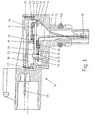
- FIG. 1 A first embodiment of a device for Detection of pressure and temperature in the intake manifold Internal combustion engine, shown in Fig. 1 includes a Whole designated 10 housing, which is a base part 12 and a cover part 14 comprises.
- the housing 10 is divided into two rooms, one Pressure room 16 and another room 18 in which a Support 20 decoupling by mechanical tension Sealing adhesive 22 is attached to the base part 12.
- the Carrier 20 is in this case on a web 13 of base part 12 attached that the carrier 20 only on the web 13th rests.
- the web 13 is arranged at the point the bonding wires 23 are contacted on the carrier 20.
- the Bond wires 23 establish the electrical connection between Flat plug contacts 30, which are arranged in the base part 12 are, and the electrical connection lines on the Carrier 20 represents.
- a pressure sensor known per se is on the carrier 20 40 arranged of a glass base and one on this arranged silicon chip on the Surface e.g. an evaluation circuit is provided, for example in the form of a Wheatstone bridge Piezoresistive resistance elements is constructed.
- the membrane necessary for pressure detection is by etching the silicon chip back.
- the connection of the Silicon chips with the glass base is under vacuum manufactured so that it can then be etched into the Cavern a vacuum is located.
- the pressure sensor 40 facing the cover part 14 is from a ring 42, for example an IC ring.
- the Gap 44 between the ring 42 and the pressure sensor 40 is filled with a fluorosilicone gel.
- fluorosilicone gel ensures that the Pressure sensor 40 including its thin wire gold bonds before a touch and a contact with in one Internal media existing media, such as Gasoline or exhaust gas condensate is protected.
- the pressure sensor 40 is on a part 21 of the carrier 20 arranged, which protrudes into the pressure chamber 16.
- the pressure room 16 is connected to the base part 12 in one piece Connector 15 with the (not shown) Intake pipe of the internal combustion engine connected.
- the evaluation circuit is preferably on the chip of the pressure sensor 40 applied. It is also possible to do this on the the cover 40 facing, located in the pressure chamber 16 Apply side of the carrier 20.
- EMC protective circuit e.g. outside the pressure room, for example in room 18 be provided.
- a support surface can be provided in the pressure part 16 on the base part 17 may be provided on which the free end of the Part 21 of the carrier 20 via mechanical tension decoupling sealing adhesive connection 25 attached is. This is mainly for assembly and prevents that the carrier 20 during assembly in the pressure chamber 16th into it over.
- the cover 14 is also through with the base part 12 sealing connections that isolate mechanical tension 27 connected.
- the cover 14 has one adjacent to the pressure sensor 40 Wall 19 on, with the carrier 20 via a, mechanical Tension-isolating sealing adhesive connection 28 connected is. Through this wall 19 is special easy way a pressure-tight subdivision of the housing achieved in the two rooms 16, 18. Serves at the same time the wall 19 of the stabilization of the beam 20.
- a temperature sensor 70 is in the base part 12 arranged that it protrudes into the nozzle 15.
- the Connection line 71 of the temperature sensor 70 are through the sealing adhesive connection 21 between the base part 12 and carried the carrier 20.
- FIGS. 1 and 2 is the temperature sensor in the form of an NTC resistor by a molded onto the nozzle 15 resilient clip bracket 95 attached.
- the clip bracket 95 is shown in Fig. 2 in the unmounted state.
- to Attachment of the connecting line 71 of the temperature sensor 70 are two clamping elements 96, which in their the Connection lines 71 of the temperature sensor 70 facing have front lugs 97, such in am Clip bracket 95 provided latching openings 98 along the arrows A shown directions that at the Jaws 96 formed clamping surfaces 99 on the connecting lines 71 of the temperature sensor 70 come to rest and this on projections 91, which on the nozzle part 15th molded, clamp.
- the clip bracket 95 is there designed so that an O-ring seal 100 (Fig. 1) for Seal the connector 15 only on the connector 15 can be deferred when the temperature sensor 70 by the clip connection already described on the Nozzle part 15 is attached.
- the angled connecting leads 71 of the temperature sensor 70 after going through the sealing adhesive joints 22 are brought out, by means of one per se known insulation displacement connection 73 with plug contact pins 30 electrically connected.
- the plug contact pins 30 point to this in their lower area (Not shown) V-shaped openings in which the Connection lines 71 of the temperature sensor 70 on itself in a known manner.
- Both the temperature sensor 70 and its connecting lines 71 are made of a polyesterimide protective lacquer coated, which not only protects against media, the outside of the temperature sensor 70 and its Act on connecting line 70, is accomplished, but also a particularly favorable response time of the Temperature sensor is reached.
- pressure sensor 40 in Pressure chamber 16 is particularly advantageous ensures that the entire pressure sensor 40 in the medium under pressure, which causes tension in the pressure sensor that occurs on one side Actuation of the pressure sensor with the under Media under pressure can be avoided become.
- the bearing surface 17 on the the part 21 of the carrier 20 on which the pressure sensor 40 is attached via a sealing adhesive connection 25 is not absolutely necessary. Rather can the part 21 of the carrier 20 on which the pressure sensor 40 is also freely suspended in the pressure chamber 16 protrude.
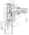
- the temperature sensor 70 is not through a clip connection attached to the nozzle 15, but in one for him Intended recording inserted from above.
- the connecting lines 71 of the temperature sensor 70 are angled and at their ends in between the base part 12 and the sealing adhesive connection 22 arranged on the carrier 20 attached.
- the connecting leads 71 of the temperature sensor 70 are exposed except for their contact Teflon coated ends.
- the sealing adhesive connection 22 encloses both the exposed ends as well at least a portion of the teflon coated Connection lines 71. In this way, one becomes special achieved good fastening, since the adhesive is particularly good adheres to the exposed metal connection legs.
- the pressure sensor 40 shown in FIGS. 1 and 3 becomes preferably made in the following manner. First the temperature sensor 70 on the nozzle 15 of the base part 12 attached in the manner described above. Thereupon the electrical connecting lines 71 of the temperature sensor 70 with the plug contact pins 30 contacted. This can be done, for example, with conductive adhesive connections happen. In this case the curing time such conductive adhesive connections in particular advantageously combined with the curing time the sealing adhesive connections to be described below, through which the carrier is attached to the base part becomes.
- the carrier 20 is passed through on the base part 12 the sealing adhesive connection 22, which mechanical tension largely decouple, attached. thereupon become the electrical contacts between the conductor tracks on the carrier 20 and the plug contact pins 30 made by bond wires 23.
- the Cover 14 by sealing adhesive connections 19 between the Carrier 20 and cover 14 and 27 between cover 14 and the base part 12 attached to the base part 12.
Landscapes
- Physics & Mathematics (AREA)
- General Physics & Mathematics (AREA)
- Chemical & Material Sciences (AREA)
- Engineering & Computer Science (AREA)
- Combustion & Propulsion (AREA)
- Analytical Chemistry (AREA)
- Measuring Fluid Pressure (AREA)
- Testing Or Calibration Of Command Recording Devices (AREA)
- Measuring Temperature Or Quantity Of Heat (AREA)
Abstract
Description
- Befestigen eines Temperatursensors mit Anschlußleitungen in einem Basisteil eines Gehäuses;
- Herstellung der elektrischen Kontaktierung der Anschlußleitungen mit Sfceckerkontaktstiften, die in dem Basisteil vorgesehen sind;
- Befestigen eines Trägers durch mechanische Verspannungen entkoppelnde Dichtklebungen an dem Basisteil;
- Kontaktierung der elektrischen Kontaktelemente des Trägers mit Kontaktelementen, die in dem Basisteil vorgesehen sind, und
- Befestigen eines Deckelteils an dem Träger und an dem Basisteil durch mechanische Verspannungen entkoppelnde Dichtklebungen.
- Fig. 1
- eine Schnittdarstellung eines ersten Ausführungsbeispiels einer erfindungsgemäßen Vorrichtung zur Erfassung des Drucks und der Temperatur im Saugrohr einer Brennkraftmaschine;
- Fig. 2
- eine schematische Draufsicht eines der Befestigung eines Temperatursensors dienenden, an dem Stutzenteil angeordneten Clipsbügels;
- Fig. 3
- eine Schnittdarstellung eines zweiten Ausführungsbeispiels einer erfindungsgemäßen Vorrichtung zur Erfassung des Drucks und der Temperatur im Saugrohr einer Brennkraftmaschine und
- Fig. 4
- eine aus dem Stand der Technik bekannte Vorrichtung zur Erfassung des Drucks und der Temperatur im Saugrohr einer Brennkraftmaschine.
Claims (15)
- Vorrichtung zur Erfassung des Drucks und der Temperatur im Saugrohr einer Brennkraftmaschine, wobei in einem gemeinsamen Gehäuse (10) ein Temperatursensor (70) und ein auf einem Träger (20) zusammen mit einer Auswerteschaltung weitestgehend verspannungsarm befestigter Drucksensor (40) angeordnet sind, wobei das Gehäuse (10) wenigstens zwei voneinander getrennte Räume (16, 18) umfaßt, dessen einer einen mit dem Saugrohr über einen Stutzen (15) verbundenen, gegenüber der Umgebung abgedichteten Druckraum (16) bildet, in dem der Teil (21) des Trägers (20) angeordnet ist, auf dem der Drucksensor (40) befestigt ist, und dessen anderer der Aufnahme und Befestigung des restlichen Teils des Trägers (20) mit Anschlußelementen (23) dient, wobei zur Befestigung des Trägers (20) und zur Abdichtung des Drucksensors (40) mechanische Spannungen entkoppelnde Dichtklebeverbindungen (22, 28) vorgesehen sind sowie der Stutzen (15) einstückig mit dem Gehäuse (10) verbunden und der Temperatursensor (70) in dem Stutzen (15) angeordnet ist.
- Vorrichtung nach Anspruch 1, dadurch gekennzeichnet, daß das Gehäuse (10) ein Basisteil (12), an dem der Stutzen (15) angeordnet und die Trägerplatte durch mechanische Spannungen entkoppelnde Dichtklebeverbindungen (22) befestigt ist, und ein mit dem Basisteil (12) verbundenes Deckelteil (14) umfaßt, das über dem Träger liegend angeordnet und eine Wand (19) zur Ausbildung der beiden Räume (16, 18) aufweist, die mit dem Träger (20) durch eine, mechanische Spannungen entkoppelnde Dichtklebeverbindung (28) verbunden ist.
- Vorrichtung nach Anspruch 2, dadurch gekennzeichnet, daß der Deckelteil (14) an dem Basisteil (12) ausschließlich über mechanische Spannungen entkoppelnde Dichtklebeverbindungen (27) befestigt ist.
- Vorrichtung nach Anspruch 2, dadurch gekennzeichnet, daß an dem Basisteil in dem Druckraum (16) eine Auflagefläche (17) vorgesehen ist, an der der Träger durch eine, mechanische Spannungen entkoppelnde Dichtklebung (25) befestigt ist.
- Vorrichtung nach einem der Ansprüche 1 bis 4, dadurch gekennzeichnet, daß um den Drucksensor (40) ein Ring (42) angeordnet ist und daß der Zwischenraum (44) zwischen dem Ring (42) und dem Drucksensor (40) mit einem chemikalienbeständigen Gel ausgefüllt ist.
- Vorrichtung nach Anspruch 5, dadurch gekennzeichnet, daß das chemikalienbeständige Gel ein Fluorsilikon-Gel ist.
- Vorrichtung nach einem der Ansprüche 1 bis 6, dadurch gekennzeichnet, daß der Temperatursensor (70) an dem Basisteil (12) derart befestigt ist, daß er in das Innere des Stutzens (15) ragt.
- Vorrichtung nach Anspruch 7, dadurch gekennzeichnet, daß Anschlußleitungen (71) des Temperatursensors (70) durch einen an dem Stutzen (15) angeformten federnden Clipsbügel (95) an zwei an dem Stutzen (15) ausgebildete Backen geklemmt werden.
- Vorrichtung nach Anspruch 8, dadurch gekennzeichnet, daß der Temperatursensor (70) und dessen Anschlußleitungen (71) mit einem Schutzlack oder einer Schutzbeschichtung, vorzugsweise einem Polyesterimidlack, überzogen sind.
- Vorrichtung nach Anspruch 8 oder 9, dadurch gekennzeichnet, daß die Anschlußleitung (71) des Temperatursensors durch eine oder mehrere Dichtklebeverbindungen (22) zwischen dem Träger (20) und dem Basisteil (12) geführt sind.
- Vorrichtung nach Anspruch 7, dadurch gekennzeichnet, daß der Temperatursensor (70) in eine in dem Stutzen ausgebildete Aufnahme geschoben und durch eine Klebeverbindung (22), die zwischen dem Träger und dem Basisteil angeordnet ist und die Enden der Anschlußleitungen (71) des Temperatursensors (70) umschließt, befestigt ist.
- Vorrichtung nach Anspruch 11, dadurch gekennzeichnet, daß die Anschlußleitungen (71) des Temperatursensors (70) bis auf ihre zur Kontaktierung freiliegenden Enden teflonbeschichtet sind und daß sowohl die freiliegenden Enden als auch wenigstens ein Teilabschnitt der teflonbeschichteten Anschlußleitungen (71) in der Klebeverbindung (22) eingebettet sind.
- Vorrichtung nach einem der voranstehenden Ansprüche, dadurch gekennzeichnet, daß zur Kontaktierung der Anschlußleitungen (71) des Temperatursensors (70) mit im Basisteil (12) angeordneten, nach außen geführten Steckerkontaktstiften (30) Schneidklemmverbindungen (73) vorgesehen sind.
- Vorrichtung nach einem der Ansprüche 1 bis 12, dadurch gekennzeichnet, daß zur Kontaktierung der Anschlußleitungen (71) des Temperatursensors (70) mit im Basisteil (12) angeordneten, nach außen geführten Steckerkontaktstiften (30) Leitklebeverbindungen und/oder Lötverbindungen und/oder Schweißverbindungen vorgesehen sind.
- Verfahren zur Herstellung einer Vorrichtung zur Erfassung des Drucks und der Temperatur im Saugrohr einer Brennkraftmaschine nach einem der voranstehenden Ansprüche, gekennzeichnet durch folgende SchritteBefestigen eines Temperatursensors (70) mit Anschlußleitungen (71) in einem Basisteil (12) eines Gehäuses (10);Herstellen der elektrischen Kontaktierung der Anschlußleitungen (71) mit Steckerkontaktstiften (30), die in dem Basisteil (12) vorgesehen sind;Befestigen eines Trägers (20) an dem Basisteil (12) durch elastische Dichtklebeverbindungen (22);Herstellen der elektrischen Kontakte zwischen Leiterbahnen des Trägers (20) und Steckerkontaktstiften (30) in dem Basisteil (12) undBefestigen eines Deckelteils (14) an dem Träger (20) und dem Basisteil (12) durch elastische Dichtklebeverbindungen (27, 28).
Applications Claiming Priority (3)
| Application Number | Priority Date | Filing Date | Title |
|---|---|---|---|
| DE19731420A DE19731420A1 (de) | 1997-07-22 | 1997-07-22 | Vorrichtung zur Erfassung des Drucks und der Temperatur im Saugrohr einer Brennkraftmaschine und Verfahren zu ihrer Herstellung |
| DE19731420 | 1997-07-22 | ||
| PCT/DE1998/001326 WO1999005477A1 (de) | 1997-07-22 | 1998-05-13 | Vorrichtung zur erfassung des drucks und der temperatur im saugrohr einer brennkraftmaschine und verfahren zu ihrer herstellung |
Publications (2)
| Publication Number | Publication Date |
|---|---|
| EP0927337A1 EP0927337A1 (de) | 1999-07-07 |
| EP0927337B1 true EP0927337B1 (de) | 2003-10-08 |
Family
ID=7836500
Family Applications (1)
| Application Number | Title | Priority Date | Filing Date |
|---|---|---|---|
| EP98933518A Expired - Lifetime EP0927337B1 (de) | 1997-07-22 | 1998-05-13 | Vorrichtung zur erfassung des drucks und der temperatur im saugrohr einer brennkraftmaschine und verfahren zu ihrer herstellung |
Country Status (7)
| Country | Link |
|---|---|
| US (1) | US6272913B1 (de) |
| EP (1) | EP0927337B1 (de) |
| JP (1) | JP4343276B2 (de) |
| KR (1) | KR100530434B1 (de) |
| DE (2) | DE19731420A1 (de) |
| RU (1) | RU2191358C2 (de) |
| WO (1) | WO1999005477A1 (de) |
Cited By (4)
| Publication number | Priority date | Publication date | Assignee | Title |
|---|---|---|---|---|
| DE102005048396A1 (de) * | 2005-10-10 | 2007-04-19 | Siemens Ag | Sensorbaugruppe |
| WO2012171693A1 (de) | 2011-06-17 | 2012-12-20 | Robert Bosch Gmbh | Druckmessvorrichtung |
| CN103403512A (zh) * | 2010-12-30 | 2013-11-20 | Sc2N公司 | 用于连接到机动车辆热机的气管的温度测量装置,和热机和设置有该装置的车辆 |
| DE102018222781A1 (de) | 2018-12-21 | 2020-06-25 | Robert Bosch Gmbh | Drucksensoranordnung |
Families Citing this family (62)
| Publication number | Priority date | Publication date | Assignee | Title |
|---|---|---|---|---|
| US20040067227A1 (en) * | 2001-11-02 | 2004-04-08 | Goldstein Allan L. | Inhibition or reversal of skin aging by actin-sequestering peptides |
| AU766826B2 (en) * | 1998-07-30 | 2003-10-23 | Government of The United States of America, as represented by The Secretary Department of Health & Human Services, The National Institutes of Health, The | Thymosin beta4 promotes wound repair |
| US20070015698A1 (en) * | 1998-07-30 | 2007-01-18 | United States Of America As Represented By The Secretary Of Health | Treatment of skin, and wound repair, with thymosin beta 4 |
| JP3532776B2 (ja) * | 1998-10-20 | 2004-05-31 | 株式会社日立製作所 | 自動車用センサの取付け構造 |
| DE19934248A1 (de) * | 1999-07-21 | 2001-02-08 | Siemens Ag | Drucksensor |
| DE19942511B4 (de) * | 1999-09-07 | 2005-07-14 | Robert Bosch Gmbh | Vorrichtung zur Messung wenigstens eines Parameters eines strömenden Mediums |
| US8150767B2 (en) * | 2000-02-16 | 2012-04-03 | Mastercard International Incorporated | System and method for conducting electronic commerce with a remote wallet server |
| DE10009153A1 (de) | 2000-02-26 | 2001-09-13 | Bosch Gmbh Robert | Vorrichtung zur Bestimmung von zumindest einem Parameter eines strömenden Gas-Flüssigkeitsgemischs bzw. Verwendung eines Strömungsgleichrichters als Kondensationsfalle bzw. Verfahren zur Kondensierung einer Flüssigkeit |
| EP1130238B1 (de) * | 2000-03-02 | 2004-05-26 | BING Power Systems GmbH | Drosselklappenstutzen und Verfahren zu seiner Herstellung |
| DE10013904A1 (de) * | 2000-03-21 | 2001-09-27 | Bosch Gmbh Robert | Mikromechanisches Bauelement und Abgleichverfahren |
| DE10054013B4 (de) * | 2000-11-01 | 2007-06-21 | Robert Bosch Gmbh | Drucksensormodul |
| DE10109095A1 (de) * | 2001-02-24 | 2002-09-05 | Bayerische Motoren Werke Ag | Kombinationssensor |
| DE10223357A1 (de) * | 2002-05-25 | 2003-12-04 | Bosch Gmbh Robert | Vorrichtung zur Druckmessung |
| DE10228000A1 (de) | 2002-06-22 | 2004-01-08 | Robert Bosch Gmbh | Vorrichtung zur Druckmessung |
| JP3870918B2 (ja) * | 2002-10-23 | 2007-01-24 | 株式会社デンソー | 温度センサ一体型圧力センサ装置 |
| US7370526B1 (en) | 2003-03-13 | 2008-05-13 | Rosemount Aerospace Inc. | Total air temperature probe providing a secondary sensor measurement chamber |
| US20040177683A1 (en) * | 2003-03-13 | 2004-09-16 | Ice Paul A. | Total air temperature probe providing a secondary sensor measurement chamber |
| JP3870917B2 (ja) * | 2003-03-19 | 2007-01-24 | 株式会社デンソー | 温度センサ一体型圧力センサ装置及びその温度センサ固定方法 |
| US7421258B2 (en) * | 2003-10-10 | 2008-09-02 | Rosemount Inc. | Compact temperature transmitter with improved lead connections |
| DE102004012593A1 (de) * | 2004-03-12 | 2005-09-29 | Robert Bosch Gmbh | Sensormodul |
| JP2005274412A (ja) * | 2004-03-25 | 2005-10-06 | Denso Corp | 温度センサ一体型圧力センサ装置 |
| US7213586B2 (en) * | 2004-08-12 | 2007-05-08 | Borgwarner Inc. | Exhaust gas recirculation valve |
| US20070234720A1 (en) * | 2004-08-12 | 2007-10-11 | Borgwarner Inc. | Exhaust gas recirculation valve |
| US7607638B2 (en) | 2005-03-08 | 2009-10-27 | Borgwarner Inc. | EGR valve having rest position |
| DE102005016008B4 (de) | 2005-04-07 | 2020-06-18 | Robert Bosch Gmbh | Bauelementemodul zur Anbringung auf einem Substrat |
| DE102005016002A1 (de) * | 2005-04-07 | 2006-10-12 | Robert Bosch Gmbh | Sensormodul, insbesondere für eine Klimaanlage |
| DE102006033467B4 (de) | 2006-07-19 | 2010-03-25 | Continental Automotive Gmbh | Druckerfassungsvorrichtung |
| DE102006045924B4 (de) * | 2006-09-28 | 2019-07-04 | Robert Bosch Gmbh | Druckmessvorrichtung für Kraftfahrzeuganwendungen |
| JP5196218B2 (ja) * | 2006-11-10 | 2013-05-15 | 富士電機株式会社 | 圧力センサ装置及び圧力センサ容器 |
| JP2008139298A (ja) * | 2006-11-10 | 2008-06-19 | Hitachi Ltd | 温度センサ一体型圧力センサ |
| US7478560B2 (en) * | 2007-03-08 | 2009-01-20 | Delphi Technologies, Inc. | Sensor apparatus responsive to pressure and temperature within a vessel |
| JP4983329B2 (ja) * | 2007-03-26 | 2012-07-25 | 株式会社デンソー | センサ装置 |
| JP2008261796A (ja) * | 2007-04-13 | 2008-10-30 | Denso Corp | 温度センサ一体型圧力センサ装置 |
| DE102007029720A1 (de) * | 2007-06-27 | 2009-01-08 | Robert Bosch Gmbh | Baugruppe mit einem ASIC und einem Gehäuse für den ASIC |
| DE102007045179A1 (de) | 2007-09-21 | 2009-04-02 | Robert Bosch Gmbh | Kontaktierungsmodul für Sensor mit begrenztem Bauraum |
| DE102008003848A1 (de) | 2008-01-10 | 2009-07-16 | Robert Bosch Gmbh | Kunststoffgehäuse mit integrierter Steckerschnittstelle |
| ITTO20080485A1 (it) | 2008-06-19 | 2009-12-20 | Eltek Spa | Dispositivo sensore di pressione |
| DE102008002682B4 (de) | 2008-06-26 | 2020-01-30 | Robert Bosch Gmbh | Vorrichtung zur Erfassung des Drucks und der Temperatur in einem Saugrohr einer Brennkraftmaschine |
| DE102009026472A1 (de) | 2009-05-26 | 2010-12-02 | Robert Bosch Gmbh | Temperaturmessvorrichtung zur Erfassung einer Temperatur eines strömenden fluiden Mediums |
| PL2312290T3 (pl) | 2009-10-16 | 2020-06-01 | First Sensor Mobility Gmbh | Czujnik ciśnienia i jego zastosowanie w zbiorniku płynu |
| DE102009047506A1 (de) | 2009-12-04 | 2011-06-09 | Robert Bosch Gmbh | Sensor mit einem Sensorgehäuse |
| DE102010002480A1 (de) | 2010-03-01 | 2011-09-01 | Robert Bosch Gmbh | Vorrichtung zur Fixierung eines Temperatursensors |
| JP5273076B2 (ja) * | 2010-03-24 | 2013-08-28 | 富士電機株式会社 | 温度センサ一体型半導体圧力センサ |
| DE102010015087B4 (de) | 2010-04-15 | 2021-06-17 | Andreas Stihl Ag & Co. Kg | Handgeführtes Arbeitsgerät mit Drucksensor und Temperatursensor |
| US8701476B2 (en) * | 2011-09-16 | 2014-04-22 | Tyco Electronics Brasil Ltda | Sensor assembly with resilient contact portions |
| DE102011083174B4 (de) | 2011-09-22 | 2023-11-16 | Robert Bosch Gmbh | Sensor zur Erfassung eines Drucks und einer Temperatur eines fluiden Mediums |
| DE102012204646A1 (de) | 2012-03-22 | 2013-09-26 | Robert Bosch Gmbh | Vorrichtung zur Erfassung eines Drucks und einer Temperatur eines Fluids |
| DE102012223014A1 (de) | 2012-12-13 | 2014-06-18 | Robert Bosch Gmbh | Vorrichtung zur Erfassung des Drucks und der Temperatur eines Mediums |
| DE102013209060A1 (de) | 2013-05-16 | 2014-11-20 | Robert Bosch Gmbh | Vorrichtung zur Erfassung eines Drucks und einer Temperatur eines in einem Kanal strömenden fluiden Mediums |
| CN103323154B (zh) * | 2013-05-24 | 2015-05-13 | 西安近代化学研究所 | 浇注炸药固化过程中内部应力的测量方法 |
| DE102014200093A1 (de) * | 2014-01-08 | 2015-07-09 | Robert Bosch Gmbh | Sensor zur Erfassung einer Temperatur und eines Drucks eines fluiden Mediums |
| DE102014001640B4 (de) * | 2014-02-05 | 2016-06-30 | I2S Intelligente Sensorsysteme Dresden Gmbh | Druck- und Temperatursensor-Element |
| DE102014211771A1 (de) * | 2014-06-18 | 2015-12-24 | Robert Bosch Gmbh | Temperaturmessvorrichtung zur Erfassung einer Temperatur eines strömenden fluiden Mediums |
| DE102014219030B4 (de) * | 2014-09-22 | 2016-07-07 | Robert Bosch Gmbh | Steckermodul |
| EP3203203B1 (de) * | 2014-10-03 | 2018-12-19 | TLV Co., Ltd. | Sensorvorrichtung |
| KR101578117B1 (ko) * | 2014-10-30 | 2015-12-17 | 세종공업 주식회사 | 기밀성이 향상된 온도소자 일체형 압력센서장치 |
| DE102015222115A1 (de) | 2015-11-10 | 2017-05-11 | Robert Bosch Gmbh | Vorrichtung zur Erfassung mindestens einer Eigenschaft eines fluiden Mediums und Verfahren zu ihrer Herstellung |
| DE102015223850A1 (de) | 2015-12-01 | 2017-06-01 | Robert Bosch Gmbh | Verfahren zur Herstellung einer Vorrichtung zur Erfassung mindestens einer Eigenschaft eines fluiden Mediums in einem Messraum |
| DE102016219586A1 (de) | 2016-10-10 | 2018-04-12 | Robert Bosch Gmbh | Sensorvorrichtung und Verfahren zur Herstellung einer Sensorvorrichtung |
| KR102071634B1 (ko) * | 2018-09-19 | 2020-01-30 | 주식회사 에스엠에스 | 팽창밸브용 온도 및 압력 일체형 센서 |
| RU2731836C1 (ru) * | 2020-02-23 | 2020-09-08 | Российская Федерация, от имени которой выступает Государственная корпорация по космической деятельности "РОСКОСМОС" | Устройство для определения тепловых потоков и давления в высокотемпературных высоконапорных струях |
| DE102024107848A1 (de) * | 2024-03-19 | 2025-09-25 | Tdk Electronics Ag | Kernkomponente für eine Sensoranordnung und Sensoranordnung |
Family Cites Families (15)
| Publication number | Priority date | Publication date | Assignee | Title |
|---|---|---|---|---|
| DE2851716C2 (de) * | 1978-11-30 | 1987-01-29 | Robert Bosch Gmbh, 7000 Stuttgart | Meßeinrichtung für Ansaugluft-Druck und -Temperatur |
| US4613428A (en) * | 1983-07-13 | 1986-09-23 | Katalistiks, Inc. | Hydrocarbon cracking process |
| US4644784A (en) * | 1984-11-29 | 1987-02-24 | Toyota Jidosha Kabushiki Kaisha | Suction pipe pressure detection apparatus |
| JPH02201054A (ja) * | 1989-01-31 | 1990-08-09 | Japan Electron Control Syst Co Ltd | 内燃機関の吸気圧力検出装置 |
| WO1994010548A1 (en) * | 1991-06-07 | 1994-05-11 | Maclean-Fogg Company | Resistive strain gauge pressure sensor |
| DE4317312A1 (de) * | 1993-05-25 | 1994-12-01 | Bosch Gmbh Robert | Drucksensor in einem Kunststoffgehäuse und Verfahren zur Herstellung |
| JP2991014B2 (ja) * | 1993-10-08 | 1999-12-20 | 三菱電機株式会社 | 圧力センサ |
| US5465626A (en) * | 1994-04-04 | 1995-11-14 | Motorola, Inc. | Pressure sensor with stress isolation platform hermetically sealed to protect sensor die |
| RU2122187C1 (ru) * | 1994-04-20 | 1998-11-20 | Александров Юрий Иванович | Калориметрический способ измерения энергии сгорания газообразного топлива и других легколетучих органических соединений и устройство для его осуществления |
| IT1268604B1 (it) * | 1994-09-30 | 1997-03-06 | Marelli Autronica | Dispositivo sensore multifunzione. |
| JPH09158775A (ja) * | 1995-12-06 | 1997-06-17 | Toyota Motor Corp | 内燃機関の吸気圧センサ異常検出装置 |
| JP3741290B2 (ja) * | 1996-03-29 | 2006-02-01 | スズキ株式会社 | 圧力センサの故障診断制御装置 |
| DE19634975C1 (de) * | 1996-08-29 | 1998-04-16 | Siemens Ag | Diagnoseeinrichtung zum Überwachen eines Abgasrückführsystems einer Brennkraftmaschine |
| DE19711939A1 (de) * | 1997-03-21 | 1998-09-24 | Bosch Gmbh Robert | Vorrichtung zur Erfassung des Drucks und der Temperatur im Saugrohr einer Brennkraftmaschine |
| US6014961A (en) * | 1998-07-23 | 2000-01-18 | Ford Global Technologies, Inc. | Internal combustion engine intake sensing system |
-
1997
- 1997-07-22 DE DE19731420A patent/DE19731420A1/de not_active Withdrawn
-
1998
- 1998-05-13 DE DE59809860T patent/DE59809860D1/de not_active Expired - Lifetime
- 1998-05-13 US US09/254,951 patent/US6272913B1/en not_active Expired - Lifetime
- 1998-05-13 EP EP98933518A patent/EP0927337B1/de not_active Expired - Lifetime
- 1998-05-13 WO PCT/DE1998/001326 patent/WO1999005477A1/de not_active Ceased
- 1998-05-13 JP JP50915099A patent/JP4343276B2/ja not_active Expired - Fee Related
- 1998-05-13 RU RU99107654/28A patent/RU2191358C2/ru active
- 1998-05-13 KR KR10-1999-7002362A patent/KR100530434B1/ko not_active Expired - Lifetime
Cited By (6)
| Publication number | Priority date | Publication date | Assignee | Title |
|---|---|---|---|---|
| DE102005048396A1 (de) * | 2005-10-10 | 2007-04-19 | Siemens Ag | Sensorbaugruppe |
| CN103403512A (zh) * | 2010-12-30 | 2013-11-20 | Sc2N公司 | 用于连接到机动车辆热机的气管的温度测量装置,和热机和设置有该装置的车辆 |
| CN103403512B (zh) * | 2010-12-30 | 2016-06-08 | Sc2N公司 | 用于连接到机动车辆热机的气管的温度测量装置,和热机和设置有该装置的车辆 |
| WO2012171693A1 (de) | 2011-06-17 | 2012-12-20 | Robert Bosch Gmbh | Druckmessvorrichtung |
| DE102011077686A1 (de) | 2011-06-17 | 2012-12-20 | Robert Bosch Gmbh | Druckmessvorrichtung |
| DE102018222781A1 (de) | 2018-12-21 | 2020-06-25 | Robert Bosch Gmbh | Drucksensoranordnung |
Also Published As
| Publication number | Publication date |
|---|---|
| KR100530434B1 (ko) | 2005-11-23 |
| JP2001501316A (ja) | 2001-01-30 |
| WO1999005477A1 (de) | 1999-02-04 |
| DE59809860D1 (de) | 2003-11-13 |
| EP0927337A1 (de) | 1999-07-07 |
| KR20010029531A (ko) | 2001-04-06 |
| RU2191358C2 (ru) | 2002-10-20 |
| JP4343276B2 (ja) | 2009-10-14 |
| DE19731420A1 (de) | 1999-01-28 |
| US6272913B1 (en) | 2001-08-14 |
Similar Documents
| Publication | Publication Date | Title |
|---|---|---|
| EP0923717B1 (de) | Vorrichtung zur erfassung des drucks und der temperatur im saugrohr einer brennkraftmaschine | |
| DE19731420A1 (de) | Vorrichtung zur Erfassung des Drucks und der Temperatur im Saugrohr einer Brennkraftmaschine und Verfahren zu ihrer Herstellung | |
| EP1269135B1 (de) | Drucksensormodul | |
| DE69526999T2 (de) | Spannungsisolierter Halbleiter-Druckwandler | |
| EP2047223B1 (de) | Druckerfassungsvorrichtung | |
| WO2001073391A1 (de) | Sensoranordnung | |
| EP1518098A1 (de) | Hochdruck-sensor mit silizium-membran und lotschicht | |
| EP0357717A1 (de) | Druckmessvorrichtung. | |
| DE102012223014A1 (de) | Vorrichtung zur Erfassung des Drucks und der Temperatur eines Mediums | |
| DE102019216086A1 (de) | Temperatursensorvorrichtung | |
| DE102017216734A1 (de) | Halbleiter-Differenzdrucksensor | |
| WO1997037204A1 (de) | Drucksensor und verfahren zur herstellung eines drucksensors | |
| DE19626081A1 (de) | Halbleiter-Bauelement | |
| DE102016216974A1 (de) | Druckmesszelle und Verfahren zum Beschichten und Kontaktieren eines Trägers einer Druckmesszelle | |
| DE19626084A1 (de) | Drucksensorvorrichtung für eine Montage auf der Bestückungsoberfläche einer Leiterplatte | |
| DE1773365B1 (de) | Piezoresistive einbauelemente fuer druck und kraftmessung | |
| DE102017212422A1 (de) | Drucksensoranordnung und Verfahren zu deren Herstellung | |
| DE3200448C2 (de) | Verfahren zur Herstellung einer Halbleiter-Druckwandleranordnung | |
| DE20111343U1 (de) | Messwerk zur Differenzdruckmessung | |
| EP3384264B1 (de) | Verfahren zur herstellung einer vorrichtung zur erfassung mindestens einer eigenschaft eines fluiden mediums in einem messraum | |
| DE102005020345A1 (de) | Dichtungsstruktur für einen Verbinder | |
| DE102005053876A1 (de) | Drucksensor-Bauteil | |
| DE102019206840A1 (de) | Sensoranordnung zur Bestimmung eines Drucks eines fluiden Mediums | |
| DE102004048979B4 (de) | Sensor mit wenigstens einem beheizten Sensorelement | |
| DE4327104C2 (de) | Drucksensor-Chipstruktur mit einer Klemmeinrichtung zum Kontaktieren und Halten derselben sowie mit einem Fluidverbinderteil |
Legal Events
| Date | Code | Title | Description |
|---|---|---|---|
| PUAI | Public reference made under article 153(3) epc to a published international application that has entered the european phase |
Free format text: ORIGINAL CODE: 0009012 |
|
| AK | Designated contracting states |
Kind code of ref document: A1 Designated state(s): DE FR GB |
|
| 17P | Request for examination filed |
Effective date: 19990804 |
|
| 17Q | First examination report despatched |
Effective date: 20030124 |
|
| GRAH | Despatch of communication of intention to grant a patent |
Free format text: ORIGINAL CODE: EPIDOS IGRA |
|
| GRAS | Grant fee paid |
Free format text: ORIGINAL CODE: EPIDOSNIGR3 |
|
| GRAA | (expected) grant |
Free format text: ORIGINAL CODE: 0009210 |
|
| AK | Designated contracting states |
Kind code of ref document: B1 Designated state(s): DE FR GB |
|
| REG | Reference to a national code |
Ref country code: GB Ref legal event code: FG4D Free format text: NOT ENGLISH |
|
| REF | Corresponds to: |
Ref document number: 59809860 Country of ref document: DE Date of ref document: 20031113 Kind code of ref document: P |
|
| GBT | Gb: translation of ep patent filed (gb section 77(6)(a)/1977) |
Effective date: 20040113 |
|
| ET | Fr: translation filed | ||
| PLBE | No opposition filed within time limit |
Free format text: ORIGINAL CODE: 0009261 |
|
| STAA | Information on the status of an ep patent application or granted ep patent |
Free format text: STATUS: NO OPPOSITION FILED WITHIN TIME LIMIT |
|
| 26N | No opposition filed |
Effective date: 20040709 |
|
| PGFP | Annual fee paid to national office [announced via postgrant information from national office to epo] |
Ref country code: GB Payment date: 20070523 Year of fee payment: 10 |
|
| GBPC | Gb: european patent ceased through non-payment of renewal fee |
Effective date: 20080513 |
|
| PG25 | Lapsed in a contracting state [announced via postgrant information from national office to epo] |
Ref country code: GB Free format text: LAPSE BECAUSE OF NON-PAYMENT OF DUE FEES Effective date: 20080513 |
|
| PGFP | Annual fee paid to national office [announced via postgrant information from national office to epo] |
Ref country code: FR Payment date: 20090519 Year of fee payment: 12 |
|
| REG | Reference to a national code |
Ref country code: FR Ref legal event code: ST Effective date: 20110131 |
|
| PG25 | Lapsed in a contracting state [announced via postgrant information from national office to epo] |
Ref country code: FR Free format text: LAPSE BECAUSE OF NON-PAYMENT OF DUE FEES Effective date: 20100531 |
|
| REG | Reference to a national code |
Ref country code: DE Ref legal event code: R084 Ref document number: 59809860 Country of ref document: DE Effective date: 20130301 |
|
| PGFP | Annual fee paid to national office [announced via postgrant information from national office to epo] |
Ref country code: DE Payment date: 20170718 Year of fee payment: 20 |
|
| REG | Reference to a national code |
Ref country code: DE Ref legal event code: R071 Ref document number: 59809860 Country of ref document: DE |