EP0925969A2 - Luftsteueranordnung für Klimaanlage - Google Patents
Luftsteueranordnung für Klimaanlage Download PDFInfo
- Publication number
- EP0925969A2 EP0925969A2 EP98124241A EP98124241A EP0925969A2 EP 0925969 A2 EP0925969 A2 EP 0925969A2 EP 98124241 A EP98124241 A EP 98124241A EP 98124241 A EP98124241 A EP 98124241A EP 0925969 A2 EP0925969 A2 EP 0925969A2
- Authority
- EP
- European Patent Office
- Prior art keywords
- rotation shaft
- cylindrical portion
- case
- door
- air passage
- Prior art date
- Legal status (The legal status is an assumption and is not a legal conclusion. Google has not performed a legal analysis and makes no representation as to the accuracy of the status listed.)
- Granted
Links
Images


Classifications
-
- F—MECHANICAL ENGINEERING; LIGHTING; HEATING; WEAPONS; BLASTING
- F24—HEATING; RANGES; VENTILATING
- F24F—AIR-CONDITIONING; AIR-HUMIDIFICATION; VENTILATION; USE OF AIR CURRENTS FOR SCREENING
- F24F13/00—Details common to, or for air-conditioning, air-humidification, ventilation or use of air currents for screening
- F24F13/08—Air-flow control members, e.g. louvres, grilles, flaps or guide plates
- F24F13/10—Air-flow control members, e.g. louvres, grilles, flaps or guide plates movable, e.g. dampers
- F24F13/14—Air-flow control members, e.g. louvres, grilles, flaps or guide plates movable, e.g. dampers built up of tilting members, e.g. louvre
- F24F13/1486—Air-flow control members, e.g. louvres, grilles, flaps or guide plates movable, e.g. dampers built up of tilting members, e.g. louvre characterised by bearings, pivots or hinges
-
- B—PERFORMING OPERATIONS; TRANSPORTING
- B60—VEHICLES IN GENERAL
- B60H—ARRANGEMENTS OF HEATING, COOLING, VENTILATING OR OTHER AIR-TREATING DEVICES SPECIALLY ADAPTED FOR PASSENGER OR GOODS SPACES OF VEHICLES
- B60H1/00—Heating, cooling or ventilating [HVAC] devices
- B60H1/00642—Control systems or circuits; Control members or indication devices for heating, cooling or ventilating devices
- B60H1/00664—Construction or arrangement of damper doors
- B60H1/00671—Damper doors moved by rotation; Grilles
- B60H1/00678—Damper doors moved by rotation; Grilles the axis of rotation being in the door plane, e.g. butterfly doors
-
- F—MECHANICAL ENGINEERING; LIGHTING; HEATING; WEAPONS; BLASTING
- F24—HEATING; RANGES; VENTILATING
- F24F—AIR-CONDITIONING; AIR-HUMIDIFICATION; VENTILATION; USE OF AIR CURRENTS FOR SCREENING
- F24F13/00—Details common to, or for air-conditioning, air-humidification, ventilation or use of air currents for screening
- F24F13/08—Air-flow control members, e.g. louvres, grilles, flaps or guide plates
- F24F13/10—Air-flow control members, e.g. louvres, grilles, flaps or guide plates movable, e.g. dampers
- F24F13/14—Air-flow control members, e.g. louvres, grilles, flaps or guide plates movable, e.g. dampers built up of tilting members, e.g. louvre
- F24F13/1406—Air-flow control members, e.g. louvres, grilles, flaps or guide plates movable, e.g. dampers built up of tilting members, e.g. louvre characterised by sealing means
-
- B—PERFORMING OPERATIONS; TRANSPORTING
- B60—VEHICLES IN GENERAL
- B60H—ARRANGEMENTS OF HEATING, COOLING, VENTILATING OR OTHER AIR-TREATING DEVICES SPECIALLY ADAPTED FOR PASSENGER OR GOODS SPACES OF VEHICLES
- B60H1/00—Heating, cooling or ventilating [HVAC] devices
- B60H1/00642—Control systems or circuits; Control members or indication devices for heating, cooling or ventilating devices
- B60H1/00664—Construction or arrangement of damper doors
- B60H2001/00707—Details of pivots of damper doors
-
- B—PERFORMING OPERATIONS; TRANSPORTING
- B60—VEHICLES IN GENERAL
- B60H—ARRANGEMENTS OF HEATING, COOLING, VENTILATING OR OTHER AIR-TREATING DEVICES SPECIALLY ADAPTED FOR PASSENGER OR GOODS SPACES OF VEHICLES
- B60H1/00—Heating, cooling or ventilating [HVAC] devices
- B60H1/00642—Control systems or circuits; Control members or indication devices for heating, cooling or ventilating devices
- B60H1/00664—Construction or arrangement of damper doors
- B60H2001/00714—Details of seals of damper doors
Definitions
- the present invention relates to an air passage switching system having a butterfly door for opening and closing an air passage through which air flows.
- the air passage switching system is suitable for an air outlet mode switching unit for a vehicle air conditioner.
- a conventional air passage switching system for an air conditioner of a vehicle has an air conditioning case for forming an air passage, and a butterfly door for switching the air passage.
- a rotation shaft for rotating the butterfly door is disposed at side end centers of the door.
- the butterfly door is rotatably held in the air conditioning case to be rotated by the rotation shaft.
- JP-Y2-2505278 and USP 4,402,486 respectively propose an air passage switching system in which a butterfly door is air-tightly connected to an air conditioning case around a rotation shaft.
- a seal member made of an elastic material such as rubber is attached to an outer peripheral portion of the door.
- the seal member has a brim-like protrusion portion around the rotation shaft of the door, and the protrusion portion of the seal member contacts an inner wall of the case while being pressed, so that the case around the rotation shaft is air-tightly sealed by the seal member.
- the protrusion portion of the seal member constantly slides on the inner wall of the case.
- the seal member is made of an elastic material having a relatively large friction coefficient. Therefore, a sliding friction between the seal member and the case becomes larger, thereby increasing an operation force of the door. Further, due to a dimension tolerance between the door and the case in a longitudinal direction of the rotation shaft, the protrusion portion of the seal member may not air-tightly contact the inner wall of the case, and air may be leaked from the contacting portion between the protrusion portion of the seal member and the inner wall of the case.
- a seal member made of elastic material such as rubber is attached to an outer peripheral portion of the door.
- the seal member has a cylindrical portion extending to surround the rotation shaft of the door. A diameter of the cylindrical portion is decreased toward a top end of the rotation shaft.
- the top end of the cylindrical portion of the seal member, having a smaller diameter, is press-fitted to an outer circumferential surface of a cylindrical protrusion formed on an inner surface of the case, so that the case around the rotation shaft of the door is air-tightly sealed by the seal member.
- an object of the present invention to provide an air passage switching system having a butterfly door, in which the door is air-tightly rotatably attached to a case forming an air passage while an operation force for rotating the door is decreased.
- an air passage switching system includes a case for forming an air passage and a butterfly door for opening and closing the air passage.
- the door has a door body, a rotation shaft for rotating the door body, and a seal member attached to the door body.
- a link member for rotating the rotation shaft is connected to a first end of the rotation shaft in a longitudinal direction of the rotation shaft.
- a first cylindrical portion is disposed in the door body at an outer peripheral side of the rotation shaft, and a second cylindrical portion is formed in the case to protrude toward the door.
- the rotation shaft is coupled to the case in such a manner that a gap is formed between an outer peripheral surface of the second cylindrical portion and an inner circumferential surface of the first cylindrical portion, and between the outer peripheral surface of the second cylindrical portion and an end of the seal member of the door in a radius direction of the rotation shaft.
- each of the cylindrical portions is made of inelastic material, installation portions of the air passage switching door are readily assembled, and the butterfly door is readily installed in the case while a sufficient seal performance is proposed.
- An air conditioning unit 10 of an air conditioner for a vehicle is disposed in a passenger compartment at an approximately center portion of an instrument panel (not shown) in a vehicle width direction (i.e., right-left direction).
- the instrument panel is disposed in a front part of the passenger compartment of the vehicle.
- the air conditioning unit 10 is installed in the vehicle to correspond to an arrangement direction of FIG. 1.
- a blower unit (not shown) is disposed in the passenger compartment at a front passenger's side shifted from the air conditioning unit 10 in the vehicle width direction.
- the air conditioning unit 10 has an air conditioning case 11 which forms an air passage for leading air toward the passenger compartment.
- An air inlet 11a through which air is introduced into the case 11 is formed on a most front portion of the case 11.
- An outlet of the blower unit is connected to the air inlet 11a of the case 11, so that air blown by the blower unit flows into the case 11 through the air inlet 11a.
- Air introduced into the case 11 is cooled by an evaporator 12 of a refrigerant cycle, and then is heated by a heater core 13 which heats air using hot water (i.e., engine cooling water) as a heating source.
- An amount of air passing through the heater core 13 and an amount of air bypassing the heater core 13 is adjusted by a plate-like air mixing door 15 so that the temperature of air to be blown into the passenger compartment is adjusted to have a predetermined temperature.
- the air mixing door 15 is rotated by a rotation shaft 15a in the case 11.
- a ratio between an amount of air passing through the heater core 13 and an amount of air passing through a bypass passage 14 through which air bypasses the heater core 13 is adjusted by controlling a rotation position of the air mixing door 15.
- the conditioned air is blown into the passenger compartment through at least one of three opening portions formed in the case 11.
- the three opening portions are a face opening 16 through which air is blown toward a head portion of a passenger in the passenger compartment, a defroster opening 17 through which air is blown toward an inner surface of a windshield of the vehicle, and a foot opening 18 through which air is blown toward a foot portion of the passenger.
- the face opening 16, the defroster opening 17, and the foot opening 18 are opened and closed, respectively, by a face door 19, a defroster door 20, and a foot door 21.
- the face door 19 and the defroster door 20 are butterfly doors as shown in FIGS. 1, 2.
- each of the butterfly doors 19, 20 has a door body 100 formed into a rectangular shape using an inelastic material having a high rigidity, such as resin.
- a rotation shaft 101 for rotating the door body 100 is integrally formed with the door body 100 to extend in a longitudinal direction of the door body 100, and is disposed at a center of the door body 100 in a lateral direction of the door body 100.
- both side ends of each door 19, 20 in the lateral direction are referred to as lateral side ends
- both side ends of each door 19, 20 in the longitudinal direction are referred to as longitudinal side ends.
- a seal member 102 made of an elastic material such as rubber is attached to an outer peripheral portion of the door body 100 in such a manner that the door body 100 is framed by the seal member 102.
- the door body 100 and the seal member 102 can be integrally formed, for example. That is, a rubber material of the seal member 102 is inserted into a mold for forming the door body 100, at a preset position in the mold, thereafter a resin material of the door body 100 is injected into the mold, so that the door body 100 and the seal member 102 can be integrally formed.
- the door body 100 of the door 19, 20 is made of a resin material such as polypropylene, nylon and ABS resin.
- a filler such as glass fiber may be mixed into the resin material of the door body 100 to enhance a strength of the door body 100.
- the seal member 102 is made of an elastic material such as rubber, silicone rubber and thermoplastic elastomer (TPE).
- TPE thermoplastic elastomer
- the case 11 may be made of the same resin material as that of the door body 100.
- the case 11 has door receivers 105, 106 protruding from the inner wall of the case 11 at the positions forming the face and defroster openings 16, 17.
- the door receivers 105, 106 respectively have an inclined surface 103, 104.
- a longitudinal peripheral portion 102a of the seal member 102 of the door body 100 air-tightly contacts the inclined surfaces 103, 104 of the door receives 105, 106, so that the openings 16, 17 of the case 11 can be sealed by the longitudinal peripheral portion 102a.
- FIG. 4 shows a state in which the longitudinal peripheral portion 102a of the seal member 102 is press-fitted to the inclined surface 104 of the door receiver 106.
- a lateral side portion 102b of the seal member 102 contacts door receivers 114, 115 (see FIG. 6) which protrude from the inner wall of the case 11 into the face and defroster openings 16, 17.
- the openings 16, 17 of the case 11 can be also air-tightly sealed along the lateral side ends of the doors 19, 20.
- the rotation shaft 101 of the door body 100 of the butterfly door 19, 20 has a recessed end portion 107 at one end "B" of the rotation shaft 101, and a protrusion end portion 108 at the other end "C” of the rotation shaft 101.
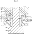
- a connection structure between the recessed end portion 107 of the rotation shaft 101 and the case 11 will be described in detail with reference to FIGS. 5-7.
- the recessed end portion 107 has an outer diameter larger than that of the other portion of the rotation shaft 101, and has a link hole 109 extending in the longitudinal direction of the rotation shaft 101.
- the link hole 109 is opened at the end "B" of the rotation shaft 101, and has a bottom having a predetermined deepness away from the end "B". Further, an inner circumferential surface of the link hole 109 is partially made flat, so that the link hole 109 has a D-shaped cross-section.
- An open end portion of the recessed end portion 107 is formed into a double cylindrical portion consisting of an outer cylindrical portion 110 and an inner cylindrical portion 111, so that a circular groove 112 is formed between the outer and inner cylindrical portions 110, 111.
- the inner wall of the case 11 forming the face and defroster openings 16, 17 is integrally formed with a cylindrical portion 113 protruding inwardly from the case 11.
- door receivers 114, 115 are also formed integrally with the inner wall of the case 11, and are disposed to be connected to the cylindrical portion 113 so that the cylindrical portion 113 is disposed between the door receivers 114, 115.
- the case 11 has a thickness t 0, and the door receivers 114, 115 protrude from the case 11 by a length t 1 .
- the door receivers 114, 115 are disposed alternately with respect to the lateral side portion 102b of the seal member 102. That is, when the door receiver 114 shown on a left side of FIG. 6 is disposed below the lateral side portion 102b of the seal member 102, the door receiver 115 shown on a right side of FIG. 6 is disposed above the lateral side portion 102b of the seal member 102. Further, each of the door receivers 114, 115 has an inclined surface similar to the inclined surfaces 103, 104 of the door receivers 105, 106, so that the sealing effect between the lateral side portion 102b of the seal member 102 and the door receivers 114, 115 of the case 11 is improved.
- an end portion of the cylindrical portion 113 of the case 11 is inserted into the circular groove 112 of the rotation shaft 101.
- an inner diameter of the cylindrical portion 113 of the case 11 is set so that a sufficient clearance is formed between an inner circumferential surface of the cylindrical portion 113 and an outer circumferential surface of the inner cylindrical portion 111 of the rotation shaft 101.
- an outer diameter of the cylindrical portion 113 of the case 11 is set so that a small gap X is formed between the inner circumferential surface of the outer cylindrical portion 110 and an outer circumferential surface of the cylindrical portion 113, and between an end portion 102c of the lateral side portion 102b and the outer peripheral surface of the cylindrical portion 113 in the radius direction.
- a dimension of the small gap X in the radius direction is set to 0.1-0.4 mm, more preferably is set to 0.1-0.2 mm, in consideration of a manufacturing tolerance.
- the cylindrical portion 113 and the outer cylindrical portion 110 are overlapped while the small gap X being formed therebetween by a length L in the longitudinal direction of the rotation shaft 101.
- the length L is set to 1-4 mm for effectively sealing of the case 11, more preferably is set to 2-3 mm.
- a link member 116 made of resin such as polyacetal has a link shaft 117.
- the link member 116 constitutes a linkage mechanism for driving the door 19, 20.
- the link shaft 117 is integrally formed with the link member 116, and has a D-shaped cross-section corresponding to that of the link hole 109 of the recessed end portion 107 of the rotation shaft 101.
- the link shaft 117 is press-inserted into the link hole 109, so that the link member 116 is connected with the recessed end portion 107 of the rotation shaft 101, while preventing the link member 116 from idling.
- the link member 116 has a cylindrical portion 118 formed concentrically on an outer peripheral side of the link shaft 117.
- a plurality of elastically deformable latch portions 119 e.g., four latch portions
- a shaft receiving portion 121 having a shaft receiving hole 120 is formed at a base of the cylindrical portion 113 of the case 11.
- a diameter of the shaft receiving hole 120 is smaller than that of the cylindrical portion 113.
- the cylindrical portion 118 of the link member 116 is inserted into the shaft receiving hole 120 and is rotatably held in the shaft receiving portion 121, while each nail portion of the latch portions 119 is engaged with a step end portion of the shaft receiving portion 121.
- the recessed end portion 107 of the rotation shaft 101 is rotatably held in the shaft receiving portion 121 of the case 11 through the link member 116, while the link member 116 is tightly engaged with the shaft receiving portion 121.
- the link member 116 is connected to and is driven by a manual operation member of a control panel of the air conditioner or an actuator using a motor through a link mechanism.
- a holding structure of the protrusion end portion 108 at the end "C" of the rotation shaft 101 is described with reference to FIG. 8.
- the inner wall of the case 11 forming the face and defroster openings 16, 17 has a shaft receiving portion 122 at a position corresponding to the protrusion end portion 108.
- the shaft receiving portion 122 is formed into a cylindrical shape having a closed bottom, and protrudes outwardly.
- the protrusion end portion 108 of the rotation shaft 101 is inserted into the shaft receiving portion 122 and is rotatably held therein.
- door receivers 123, 124 protruding from the inner wall of the case 11 are integrally formed with the case 11, and are disposed at both sides of the shaft receiving portion 122.
- the door receivers 123, 124 are also disposed alternately with respect to the lateral side portion 102b of the seal member 102. That is, when the door receiver 123 shown on a right side of FIG. 8 is disposed below the lateral side portion 102b of the seal member 102, the door receiver 124 shown on a left side of FIG. 8 is disposed above the lateral side portion 102b of the seal member 102.
- Each of the door receivers 123, 124 also has an inclined surface similar to the inclined surfaces 103, 104 of the door receivers 105, 106, so that the sealing effect between the seal member 102 and the door receivers 123, 124 is enhanced.
- the lateral side portion 102b of the seal member 102 is integrally attached not only to the door body 100, but also to an outer peripheral surface of the protrusion end portion 108 of the rotation shaft 101.
- the butterfly door 19, 20 is opened.
- the longitudinal peripheral portion 102a of the seal member 102 is press-fitted to the inclined surfaces 103, 104 of the door receivers 105, 106.
- the opening portions 16, 17 of the case 11 are air-tightly sealed at the longitudinal side ends of the door 19, 20.
- the lateral side portion 102b of the seal member 102 also is press-fitted to the door receivers 114, 115 of the case 11. Therefore, the case 11 forming the openings 16, 17 also air-tightly sealed at the rotation shaft ends of the door body 100.
- the end of the cylindrical portion 113 of the case 11 is inserted into the circular groove 112 of the rotation shaft 101, so that the small gap X is formed between the outer peripheral surface of the cylindrical portion 113, and the inner peripheral surface of the outer cylindrical portion 110 of the rotation shaft 101 and the end portion 102c of the lateral side portion 102b of the seal member 102.
- the dimension of the small gap X in the radius direction is in a range of 0.1-0.4 mm, and the outer cylindrical portion 110 of the rotation shaft 101 is overlapped with the cylindrical portion 113 of the case 11 in the longitudinal direction by the length L of 1-4 mm. Therefore, air hardly leaks from the case 11 through the small gap X.
- the openings 16, 17 of the case 11 are air-tightly sealed sufficiently around the rotation shaft 101. Further, since the seal member 102 made of an elastic material having a relatively large friction coefficient does not slide the case 11 while contacting the case 11, the operation force for operating the door 19, 20 is prevented from increasing.
- the cylindrical portion 118 of the link member 116 is rotatably held in the shaft receiving portion 121 of the case 11. Therefore, when the cylindrical portion 118 of the link member 116 rotates, a sliding friction occurs between the cylindrical portion 118 of the link member 116 and the shaft receiving portion 121 of the case 11.
- both the cylindrical portion 118 and the receiving portion 121 are made of an inelastic material having a little friction coefficient. Therefore, the operation force for operating the door 19, 20 is suppressed at minimum.
- the protrusion end portion 108 of the rotation shaft 101 slides on the shaft receiving portion 122 of the case 11, the protrusion end portion 108 and the shaft receiving portion 122 are both made of inelastic material. Therefore, the operation force for operating the door 19, 20 is suppressed at minimum.
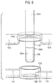
- FIGS. 9, 10 A second preferred embodiment of the present invention will be described with reference to FIGS. 9, 10.
- components which are similar to those in the first embodiment are indicated with the same reference numerals, and the explanation thereof is omitted.
- the rotation shaft 101 has the recessed end portion 107 having the link hole 109 at the end "B", and the link shaft 117 of the link member 116 is inserted into the link hole 109 so that the link member 116 is connected with the rotation shaft 101.
- a rotation shaft 101A has a protrusion end portion 108A at both ends "B", "C” of the rotation shaft 101A.
- the protrusion end portion 108A at the end "B” of the rotation shaft 101A has a cylindrical shaft portion 125.
- the cylindrical shaft portion 125 is inserted into the shaft receiving hole 120 of the shaft receiving portion 121 formed at a base of the cylindrical portion 113 of the case 11, and is rotatably held in the shaft receiving hole 120.
- An end of the protrusion end portion 108A of the rotation shaft 101A protrudes from the case 11 outwardly.
- a link portion 126 is formed into a D-shaped cross-section having a flat surface 126a, and is provided in the cylindrical shaft portion 125.
- a link hole 127 having a D-shaped cross-section is formed in a link member 116A to correspond to the D-shaped cross-section of the link portion 126.
- the link portion 126 of the cylindrical shaft portion 125 is press-inserted into the link hole 127 of the link member 116A so that the link member 116A is connected with the protrusion end portion 108A of the rotation shaft 101A, while preventing the link member 116A from idling.
- the inner diameter of the cylindrical portion 113 of the case 11 is set so that a sufficiently large opening is formed between the inner circumferential surface of the cylindrical portion 113 and an outer circumferential surface of the shaft portion 125 of the protrusion end portion 108A.
- the outer diameter of the cylindrical portion 113 of the case 11 is set so that a small gap X is formed between the outer circumferential surface of the cylindrical portion 113, and the inner circumferential surface of a cylindrical portion 110A of the rotation shaft 101A and the end portion 102c of the lateral side portion 102b of the seal member 102.
- the cylindrical portion 113 of the case 11 is overlapped with the cylindrical portion 110A of the rotation shaft 101A by a length L in a longitudinal direction of the rotation shaft 101A.
- the dimension of the small gap X in the radius direction and the length L in the longitudinal direction are set similarly to those in the first embodiment.
- the protrusion end portion 108A of the rotation shaft 101A is connected with the link member 116A by inserting the protrusion end portion 108A into the link hole 127 of the link member 116A.
- the small gap X is also formed between the outer circumferential surface of the cylindrical portion 113 of the case 11, and the inner circumferential surface of the cylindrical portion 110A of the rotation shaft 101A and the end portion 102c of the lateral side portion 102b of the seal member 102.
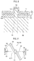
- a butterfly door 19A, 20A has the door body 100 made of a material having a high rigidity, such as resin.
- the rotation shaft 101 is integrally formed with the door body 100 at a center in the lateral direction of the door body 100.
- the rotation shaft 101 extends in the longitudinal direction of the door body 100 to protrude from the door body 100.
- the seal member 102 made of an elastic material such as rubber is attached to a half of one surface of the door body 100 on one side with respect to the rotation shaft 101, and to a half of the other surface of the door body 100 on a side opposite to the one side with respect to the rotation shaft 101.
- Door receivers 130, 131 are formed on the inner wall of the case 11 for forming the face and defroster openings 16. 17.
- the door receivers 130, 131 respectively have sealing protrusions 128, 129, which have an acute-angled tip and protrude in the opposite direction to each other.
- the seal member 102 attached to the door body 100 is press-fitted to the sealing protrusions 128, 129, so that an opening between the door receivers 130, 131 and the door body 100 can be air-tightly sealed.
- a cylindrical portion (not shown) is formed on the recessed end portion 107 or the protrusion end portion 108 of the rotation shaft 101, and a small gap is formed between the outer circumferential surface of the cylindrical portion 113 of the case 11, and an inner circumferential surface of the cylindrical portion of the rotation shaft and the end portion 102c of the side portion 102b of the seal member 102.
- the openings 16, 17 of the case 11 are air-tightly sealed with the door 19A, 20A, while preventing the operation force of the door 19A, 20A from increasing.
- the present invention is not limited to the air passage switching system of the air conditioner for the vehicle, but may be applied to an air passage switching system of various use.
Applications Claiming Priority (2)
| Application Number | Priority Date | Filing Date | Title |
|---|---|---|---|
| JP35548397 | 1997-12-24 | ||
| JP35548397A JP3840773B2 (ja) | 1997-12-24 | 1997-12-24 | 通風路切替装置 |
Publications (3)
| Publication Number | Publication Date |
|---|---|
| EP0925969A2 true EP0925969A2 (de) | 1999-06-30 |
| EP0925969A3 EP0925969A3 (de) | 2002-06-26 |
| EP0925969B1 EP0925969B1 (de) | 2006-02-15 |
Family
ID=18444214
Family Applications (1)
| Application Number | Title | Priority Date | Filing Date |
|---|---|---|---|
| EP98124241A Expired - Lifetime EP0925969B1 (de) | 1997-12-24 | 1998-12-17 | Luftsteueranordnung für Klimaanlage |
Country Status (4)
| Country | Link |
|---|---|
| US (1) | US6047951A (de) |
| EP (1) | EP0925969B1 (de) |
| JP (1) | JP3840773B2 (de) |
| DE (1) | DE69833474T2 (de) |
Cited By (5)
| Publication number | Priority date | Publication date | Assignee | Title |
|---|---|---|---|---|
| EP0983885A2 (de) * | 1998-08-25 | 2000-03-08 | Denso Corporation | Luftsteurvorrichtung für Klimaanlage |
| EP1440829A2 (de) * | 2003-01-22 | 2004-07-28 | Delphi Technologies, Inc. | Ventil mit Antiklappereigenschaft für Heizungs-, Lüftungs- und Klimaanlagen |
| EP1464523A1 (de) * | 2003-03-31 | 2004-10-06 | TRW Automotive U.S. LLC | Klappenvorrichtung für eine Kraftfahrzeugklimaanlage und Verfahren zu deren Herstellung |
| US7871316B2 (en) | 2006-06-05 | 2011-01-18 | Denso Corporation | Passage opening and closing device |
| US10393183B2 (en) | 2014-08-28 | 2019-08-27 | Mahle International Gmbh | Air control device having a bearing location |
Families Citing this family (33)
| Publication number | Priority date | Publication date | Assignee | Title |
|---|---|---|---|---|
| JP4300340B2 (ja) | 2000-02-14 | 2009-07-22 | 株式会社デンソー | 通風路切替用ドア |
| JP4395987B2 (ja) * | 2000-04-27 | 2010-01-13 | 株式会社デンソー | 通風路開閉用ドアの製造方法 |
| DE10024692A1 (de) * | 2000-05-18 | 2001-11-29 | Behr Gmbh & Co | Steuereinrichtung für Gasströme |
| JP4345240B2 (ja) * | 2000-08-25 | 2009-10-14 | 株式会社デンソー | 空調用ドアの組付構造 |
| AU2001296812A1 (en) * | 2000-10-10 | 2002-04-22 | Borgwarner Inc. | Valve plate and shaft connection |
| DE10100158A1 (de) * | 2001-01-03 | 2002-07-04 | Bosch Gmbh Robert | Klappenventil |
| JP2002219924A (ja) * | 2001-01-23 | 2002-08-06 | Zexel Valeo Climate Control Corp | 車両用空調装置の通風路切換装置 |
| US6854710B2 (en) * | 2001-10-25 | 2005-02-15 | Illinois Tool Works Inc. | Valve assembly |
| US6520850B1 (en) * | 2002-05-07 | 2003-02-18 | Valeo Climate Control Corporation | Distributor valve with integrally molded air deflector vanes for distributor box of HVAC system |
| JP3999071B2 (ja) * | 2002-08-20 | 2007-10-31 | 株式会社デンソー | 通風路切替装置の製造方法 |
| JP2004276856A (ja) * | 2003-03-18 | 2004-10-07 | Denso Corp | 通路開閉装置および車両用空調装置 |
| NO322877B1 (no) * | 2003-06-06 | 2006-12-18 | Danfoss Esco As | Sluseventil |
| DE10352533A1 (de) * | 2003-11-07 | 2005-06-02 | Behr Gmbh & Co. Kg | Trommelklappe |
| CA2484305A1 (en) * | 2004-10-08 | 2006-04-08 | Progressive Moulded Products Limited | Control wheel |
| JP4618193B2 (ja) * | 2006-06-05 | 2011-01-26 | 株式会社デンソー | 空気通路開閉装置 |
| JP4720697B2 (ja) * | 2006-09-19 | 2011-07-13 | 株式会社デンソー | 車両用空調装置 |
| US8029344B2 (en) * | 2006-11-29 | 2011-10-04 | Ford Motor Company | Door assembly for climate control system |
| JP5529364B2 (ja) * | 2007-01-26 | 2014-06-25 | 三菱重工業株式会社 | ダンパ、空気調和ユニットおよび車両用空気調和装置 |
| JP5473449B2 (ja) | 2009-07-23 | 2014-04-16 | 三菱重工業株式会社 | 車両用空調装置 |
| KR101063724B1 (ko) * | 2009-12-28 | 2011-09-07 | 주식회사 니프코코리아 | 차량용 에어벤트 |
| FR2960935B1 (fr) * | 2010-06-04 | 2012-06-08 | Ksb Sas | Robinet a joint d'etancheite en deux pieces |
| JP2013184640A (ja) * | 2012-03-09 | 2013-09-19 | Mitsubishi Heavy Ind Ltd | 車両用空調装置 |
| JP6150982B2 (ja) | 2012-03-09 | 2017-06-21 | 三菱重工業株式会社 | 車両用空調装置 |
| KR102040800B1 (ko) * | 2013-04-11 | 2019-12-05 | 삼성전자주식회사 | 블레이드 체결구조 및 이를 갖는 공기조화기 |
| DE102015200187A1 (de) * | 2014-12-19 | 2016-06-23 | Continental Automotive Gmbh | Ventilvorrichtung in einem Kraftfahrzeug und Verfahren zur Herstellung |
| JP6608678B2 (ja) * | 2015-11-12 | 2019-11-20 | 三菱重工サーマルシステムズ株式会社 | 車両用空調装置 |
| KR102592439B1 (ko) * | 2016-09-27 | 2023-10-23 | 한온시스템 주식회사 | 차량용 공조장치 |
| DE102016222918A1 (de) | 2016-11-21 | 2018-05-24 | Mahle International Gmbh | Luftsteuereinrichtung |
| JP6604318B2 (ja) * | 2016-11-30 | 2019-11-13 | 豊田合成株式会社 | 空調用レジスタ |
| DE102017120003A1 (de) * | 2017-08-31 | 2019-02-28 | Illinois Tool Works Inc. | Luftausströmer für ein Fahrzeug |
| DE102018105759A1 (de) * | 2018-03-13 | 2019-09-19 | Dr. Schneider Kunststoffwerke Gmbh | Luftleitelement mit Reibelement und Luftausströmer |
| US20190389273A1 (en) * | 2018-06-21 | 2019-12-26 | Calsonic Kansei North America Inc. | Connection structure for assembling an hvac housing with divider for multiple zones |
| DE102022110943A1 (de) | 2022-05-04 | 2023-11-09 | Dr. Ing. H.C. F. Porsche Aktiengesellschaft | Luftzuführungsvorrichtung |
Citations (2)
| Publication number | Priority date | Publication date | Assignee | Title |
|---|---|---|---|---|
| US4402486A (en) | 1980-02-18 | 1983-09-06 | Valeo | Device for mounting of a shutter in a piping of a heating or air-conditioning installation of a motor vehicle |
| JP2505278Y2 (ja) | 1990-06-26 | 1996-07-24 | 日本プラスト株式会社 | 車両用空調開閉ダンパ装置 |
Family Cites Families (6)
| Publication number | Priority date | Publication date | Assignee | Title |
|---|---|---|---|---|
| US3874631A (en) * | 1974-02-15 | 1975-04-01 | Worcester Controls Corp | Adjustable, corrosion-resistant, butterfly valve |
| US4032108A (en) * | 1975-09-17 | 1977-06-28 | Kintner Edwin K | Butterfly valve assembly |
| FR2510706B1 (fr) * | 1981-07-28 | 1985-11-22 | Valeo | Volet de commande d'un debit d'air dans une canalisation, en particulier dans une installation de chauffage ou de climatisation pour vehicule automobile |
| US4759530A (en) * | 1984-11-14 | 1988-07-26 | Neotecha Ag | Stem and disc seal construction for butterfly valves |
| FR2620523A1 (fr) * | 1988-02-03 | 1989-03-17 | Valeo | Volet pour conduit d'air, notamment pour une installation de chauffage et/ou de climatisation, en particulier pour vehicule automobile |
| US7486878B2 (en) * | 2006-09-29 | 2009-02-03 | Lam Research Corporation | Offset correction methods and arrangement for positioning and inspecting substrates |
-
1997
- 1997-12-24 JP JP35548397A patent/JP3840773B2/ja not_active Expired - Fee Related
-
1998
- 1998-12-10 US US09/209,389 patent/US6047951A/en not_active Expired - Lifetime
- 1998-12-17 EP EP98124241A patent/EP0925969B1/de not_active Expired - Lifetime
- 1998-12-17 DE DE69833474T patent/DE69833474T2/de not_active Expired - Lifetime
Patent Citations (2)
| Publication number | Priority date | Publication date | Assignee | Title |
|---|---|---|---|---|
| US4402486A (en) | 1980-02-18 | 1983-09-06 | Valeo | Device for mounting of a shutter in a piping of a heating or air-conditioning installation of a motor vehicle |
| JP2505278Y2 (ja) | 1990-06-26 | 1996-07-24 | 日本プラスト株式会社 | 車両用空調開閉ダンパ装置 |
Cited By (8)
| Publication number | Priority date | Publication date | Assignee | Title |
|---|---|---|---|---|
| EP0983885A2 (de) * | 1998-08-25 | 2000-03-08 | Denso Corporation | Luftsteurvorrichtung für Klimaanlage |
| EP0983885A3 (de) * | 1998-08-25 | 2001-04-04 | Denso Corporation | Luftsteurvorrichtung für Klimaanlage |
| EP1440829A2 (de) * | 2003-01-22 | 2004-07-28 | Delphi Technologies, Inc. | Ventil mit Antiklappereigenschaft für Heizungs-, Lüftungs- und Klimaanlagen |
| EP1440829A3 (de) * | 2003-01-22 | 2005-03-16 | Delphi Technologies, Inc. | Ventil mit Antiklappereigenschaft für Heizungs-, Lüftungs- und Klimaanlagen |
| EP1464523A1 (de) * | 2003-03-31 | 2004-10-06 | TRW Automotive U.S. LLC | Klappenvorrichtung für eine Kraftfahrzeugklimaanlage und Verfahren zu deren Herstellung |
| US7871316B2 (en) | 2006-06-05 | 2011-01-18 | Denso Corporation | Passage opening and closing device |
| DE102007026620B4 (de) * | 2006-06-05 | 2011-12-08 | Denso Corporation | Kanalöffnungs-und-Schliesseinrichtung |
| US10393183B2 (en) | 2014-08-28 | 2019-08-27 | Mahle International Gmbh | Air control device having a bearing location |
Also Published As
| Publication number | Publication date |
|---|---|
| JPH11180129A (ja) | 1999-07-06 |
| EP0925969A3 (de) | 2002-06-26 |
| JP3840773B2 (ja) | 2006-11-01 |
| DE69833474T2 (de) | 2006-10-05 |
| US6047951A (en) | 2000-04-11 |
| EP0925969B1 (de) | 2006-02-15 |
| DE69833474D1 (de) | 2006-04-20 |
Similar Documents
| Publication | Publication Date | Title |
|---|---|---|
| US6047951A (en) | Air passage switching system for air conditioner | |
| US6193600B1 (en) | Air passage switching system for air conditioner | |
| JP3663752B2 (ja) | 空気通路切替装置および車両用空調装置 | |
| US7520803B2 (en) | Air passage opening and closing device capable of preventing uncomfortable noise | |
| US7478666B2 (en) | Vehicle air conditioner | |
| US20070181295A1 (en) | Automotive air conditioning system | |
| US6688964B2 (en) | Air passage opening/closing device and vehicle air conditioner using the same | |
| US6669548B2 (en) | Inside/outside air switching device with rotary door, and vehicle air conditioner using the same | |
| US6736190B2 (en) | Vehicle air conditioner | |
| US6913529B2 (en) | Air passage switching device and vehicle air conditioner using the same | |
| US6872348B2 (en) | Manufacturing method of air passage switching door | |
| US20020070216A1 (en) | Case connection structure | |
| JP3781144B2 (ja) | 自動車用空気調和装置のドア構造 | |
| US20010008321A1 (en) | Air passage switching door and method for manufacturing the same | |
| JP3671540B2 (ja) | 空気通路切替装置および車両用空調装置 | |
| US20070281599A1 (en) | Air passage switching device | |
| US5992506A (en) | Air conditioning apparatus for vehicle | |
| JPH11115457A (ja) | 自動車用空気調和装置 | |
| JP4277644B2 (ja) | 車両用空調装置 | |
| JP4134447B2 (ja) | 空気通路切替装置 | |
| JP3584525B2 (ja) | 空気通路切換装置 | |
| JP2588863Y2 (ja) | 自動車用空気調和装置用ドア | |
| JP3677828B2 (ja) | 空気通路切換装置 | |
| JP2005349921A (ja) | 車両用空調装置のダクト接続構造 | |
| JP2004106764A (ja) | 空調装置のドア機構 |
Legal Events
| Date | Code | Title | Description |
|---|---|---|---|
| PUAI | Public reference made under article 153(3) epc to a published international application that has entered the european phase |
Free format text: ORIGINAL CODE: 0009012 |
|
| AK | Designated contracting states |
Kind code of ref document: A2 Designated state(s): AT BE CH CY DE DK ES FI FR GB GR IE IT LI LU MC NL PT SE |
|
| AX | Request for extension of the european patent |
Free format text: AL;LT;LV;MK;RO;SI |
|
| PUAL | Search report despatched |
Free format text: ORIGINAL CODE: 0009013 |
|
| AK | Designated contracting states |
Kind code of ref document: A3 Designated state(s): AT BE CH CY DE DK ES FI FR GB GR IE IT LI LU MC NL PT SE |
|
| AX | Request for extension of the european patent |
Free format text: AL;LT;LV;MK;RO;SI |
|
| 17P | Request for examination filed |
Effective date: 20020729 |
|
| AKX | Designation fees paid |
Designated state(s): DE FR GB |
|
| 17Q | First examination report despatched |
Effective date: 20040809 |
|
| GRAP | Despatch of communication of intention to grant a patent |
Free format text: ORIGINAL CODE: EPIDOSNIGR1 |
|
| GRAS | Grant fee paid |
Free format text: ORIGINAL CODE: EPIDOSNIGR3 |
|
| GRAA | (expected) grant |
Free format text: ORIGINAL CODE: 0009210 |
|
| AK | Designated contracting states |
Kind code of ref document: B1 Designated state(s): DE FR GB |
|
| REG | Reference to a national code |
Ref country code: GB Ref legal event code: FG4D |
|
| REF | Corresponds to: |
Ref document number: 69833474 Country of ref document: DE Date of ref document: 20060420 Kind code of ref document: P |
|
| ET | Fr: translation filed | ||
| PLBE | No opposition filed within time limit |
Free format text: ORIGINAL CODE: 0009261 |
|
| STAA | Information on the status of an ep patent application or granted ep patent |
Free format text: STATUS: NO OPPOSITION FILED WITHIN TIME LIMIT |
|
| 26N | No opposition filed |
Effective date: 20061116 |
|
| PGFP | Annual fee paid to national office [announced via postgrant information from national office to epo] |
Ref country code: DE Payment date: 20141211 Year of fee payment: 17 Ref country code: GB Payment date: 20141219 Year of fee payment: 17 |
|
| PGFP | Annual fee paid to national office [announced via postgrant information from national office to epo] |
Ref country code: FR Payment date: 20141219 Year of fee payment: 17 |
|
| REG | Reference to a national code |
Ref country code: DE Ref legal event code: R119 Ref document number: 69833474 Country of ref document: DE |
|
| GBPC | Gb: european patent ceased through non-payment of renewal fee |
Effective date: 20151217 |
|
| REG | Reference to a national code |
Ref country code: FR Ref legal event code: ST Effective date: 20160831 |
|
| PG25 | Lapsed in a contracting state [announced via postgrant information from national office to epo] |
Ref country code: GB Free format text: LAPSE BECAUSE OF NON-PAYMENT OF DUE FEES Effective date: 20151217 Ref country code: DE Free format text: LAPSE BECAUSE OF NON-PAYMENT OF DUE FEES Effective date: 20160701 |
|
| PG25 | Lapsed in a contracting state [announced via postgrant information from national office to epo] |
Ref country code: FR Free format text: LAPSE BECAUSE OF NON-PAYMENT OF DUE FEES Effective date: 20151231 |