EP0925450B1 - Dickstoffpumpe - Google Patents
Dickstoffpumpe Download PDFInfo
- Publication number
- EP0925450B1 EP0925450B1 EP97936648A EP97936648A EP0925450B1 EP 0925450 B1 EP0925450 B1 EP 0925450B1 EP 97936648 A EP97936648 A EP 97936648A EP 97936648 A EP97936648 A EP 97936648A EP 0925450 B1 EP0925450 B1 EP 0925450B1
- Authority
- EP
- European Patent Office
- Prior art keywords
- container
- thick matter
- feed
- matter pump
- rib
- Prior art date
- Legal status (The legal status is an assumption and is not a legal conclusion. Google has not performed a legal analysis and makes no representation as to the accuracy of the status listed.)
- Expired - Lifetime
Links
- 239000000126 substance Substances 0.000 title 1
- 239000000463 material Substances 0.000 claims description 43
- 238000005452 bending Methods 0.000 description 2
- 238000010276 construction Methods 0.000 description 2
- 239000004035 construction material Substances 0.000 description 1
- 239000007788 liquid Substances 0.000 description 1
- 238000004519 manufacturing process Methods 0.000 description 1
- 238000000034 method Methods 0.000 description 1
- 238000005086 pumping Methods 0.000 description 1
Images

Classifications
-
- F—MECHANICAL ENGINEERING; LIGHTING; HEATING; WEAPONS; BLASTING
- F04—POSITIVE - DISPLACEMENT MACHINES FOR LIQUIDS; PUMPS FOR LIQUIDS OR ELASTIC FLUIDS
- F04B—POSITIVE-DISPLACEMENT MACHINES FOR LIQUIDS; PUMPS
- F04B7/00—Piston machines or pumps characterised by having positively-driven valving
- F04B7/0019—Piston machines or pumps characterised by having positively-driven valving a common distribution member forming a single discharge distributor for a plurality of pumping chambers
- F04B7/0034—Piston machines or pumps characterised by having positively-driven valving a common distribution member forming a single discharge distributor for a plurality of pumping chambers and having an orbital movement, e.g. elbow-pipe type members
Definitions
- the material being conveyed is during the backward stroke of the piston of the one feed cylinder from the material feed container into this cylinder sucked in while at the same time forward stroke the piston of the other delivery cylinder, the conveyed goods previously sucked into this through the swivel tube is pressed into the delivery line.
- the wear ring arranged on the swivel tube that the swivel tube at the respective pressure stroke of a delivery cylinder tight against the front Spectacle-shaped openings delimiting openings of the delivery cylinders Wear plate is present to prevent Liquid or fine-grained components of the conveyed material can exit the material to be conveyed at this point.
- the invention has for its object the known Thick matter pump of the type specified above to improve that a reliable seal between Swivel tube and delivery cylinders guaranteed during the pressure stroke is.
- the invention proposes that the clearing rib on the wear ring the end facing away from the swivel tube a wear plate aligned vertically to the swivel axis bears against one on a conveyor tube side Container wall arranged and preferably adjustable axially parallel to this container wall Wear bar is present.
- the wear plate is appropriately arranged at the level of the wear ring, while the swivel tube in a pivot bearing Back wall is axially slidably mounted.
- the wear plate and form the associated wear strip a support bearing that has an axial limit in the area of the swivel tube pivot bearing, and that ensures that there is no pressure stroke on the axle shaft Attack tensile and bending forces.
- Wear trap a simple and convenient readjustment of the swivel tube inside the material feed container without additional assembly work in the area of the switching mechanism possible.
- the clearing rib is useful through in the two Swinging directions, mirror-symmetrical to one containing the swivel axis and the wear ring axis Radial plane arranged broad side surfaces limited. So that the material to be conveyed is on the ground lifted from the bottom of the container each time it switches over be mixed with the material above can, are according to a preferred embodiment of the invention, the broad side surfaces of the clearing rib free rib edge on the bottom with enlargement the rib wall thickness on opposite sides preferably curved outward by about 90 °.
- the material feed container can be a easy to manufacture, concentric to the swivel axis have partially cylindrical bottom, while the container bottom facing rib edge also one for Pivot axis essentially coaxial, partially cylindrical can have convex curvature.
- Two-cylinder thick matter pump is for use in stationary and mobile concrete pumps.
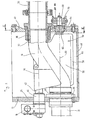
- she consists consisting essentially of two delivery cylinders 10 pushing piston, not shown, a material feed container 14 and an in the material feed container 14 engaging S-shaped Swivel tube 16, which with a reversing mechanism 18th can be actuated.
- the feed cylinder 10 are in the lower Area via openings 22 on the rear wall 24 of the material feed container 14 connected, the openings 22 on the inside of the material feed container 14 through an eyeglass-shaped wear plate 26 are limited.
- the swivel tube 16 lies with its one a wear ring 28 bearing end against the Wear plate 26 and is by the reversing mechanism 18 depending on the direction of movement the delivery piston in the delivery cylinders 10 in front of one or other opening 22 pivoted. That way with the feed piston moved back, material from the material feed container 14 through the opening 22 in the concerned Feed cylinder 10 sucked in while over the other delivery piston material through the swivel tube 16 into an outside of the material feed container 14 located conveyor pipe 30 is transported.
- the delivery pipe 30 can be connected to a delivery line, not shown of a concrete placing boom.
- Fig. 1 that is essentially S-shaped swivel tube its end 32 opposite the wear ring 28 via a container-fixed, coaxial to its pivot axis 34
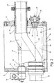
- Pipe rotary connection 36 connected to the delivery pipe 30, while in the embodiment shown with FIG. 2 the end 32 of the swivel tube on the conveyor tube side by a simple rotary union 38 in the relevant container wall 40 is passed. in the latter case is an external pivot bearing with an additional pipe slewing ring required.
- the container wall 40 is from the material feed container in both cases removable for assembly and disassembly purposes.
- the swivel tube engages in the area of the rear wall 24 an axle shaft 42 designed as a drive shaft by a pivot bearing 44 of the material feed container 14 therethrough.
- the axle shaft 42 is on the outside of the Material feed container 14 by the reversing mechanism 18 about the pivot axis 34 in the direction of the double arrow 46 (Fig. 3) pivoted back and forth. How 3 is the bottom 48 of the material feed container 14 along its entire length Pivot axis 34 is curved concentrically in a partially cylindrical manner.
- Dead spaces within the material feed container 14 To avoid as much as possible is on the swivel tube 16 downward facing, almost the whole Swing tube length extending and close to the Container bottom 48 reaching broach 50 formed, the by mirror symmetry pointing in the two swivel directions to the pivot axis 34 and the Radial plane 54 containing wear ring axis 52 Broad side surfaces 56 is limited.
- the Broad side surfaces 56 are for free bottom side Rib edge 58 towards increasing the thickness of the rib edge on the opposite sides concave to the outside curved and ensure that the material to be conveyed near the ground Range moved upwards with each switchover becomes.
- the rib edge facing the container bottom 48 58 points in the embodiment shown a partially cylindrical convex to the pivot axis 34 Curvature so that between the bottom of the container and only a narrow gap 60 remains on the rib edge.
- the end face On the locking ring 28 facing away from the swivel tube the end face carries the clearing rib 50 also a vertically aligned with the pivot axis 34, arranged at the level of the wear ring 28 wear plate 62, against one on the container wall 40 arranged and adjustable with respect to this axially parallel Wear bar 64 is present.
- the wear bar is arranged on an adjuster for this purpose, which is guided in an opening 66 in the container wall 40, sealed against this and with a Adjustment mechanism arranged on the outside on the container wall 40 68 is displaceable.
- the wear bar 64 serves the pivot tube as a support bearing, the one Axial limitation in the area of the swivel tube bearing dispensable and a tensile and bending stress the axle shaft 42 avoids. Besides, with these measures a simple adjustment of the swivel tube in the In the event of wear in the area of the wear ring 28 and the spectacle-shaped wear plate 26 possible.
- the invention relates to a thick matter pump especially for promotion of concrete.
- the thick matter pump has a material feed container 14, two with their front Openings 22 into the interior of the material feed container 14 discharge cylinder 10 and one in the material feed container 14 engaging, with one end cyclically alternating with the front openings 22 of the feed cylinder 10 communicating and with his other end 32 connected to a conveyor pipe 30 S-shaped swivel tube on.
- the swivel tube is over one concentric to its end 32 on the conveyor tube side, horizontal arranged above the feed cylinder 10 Pivot axis 34 can be pivoted.
Landscapes
- Engineering & Computer Science (AREA)
- Mechanical Engineering (AREA)
- General Engineering & Computer Science (AREA)
- Reciprocating Pumps (AREA)
Description
- Fig. 1
- einen Schnitt durch den Materialaufgabebehälter einer Zweizylinder-Dickstoffpumpe mit Sförmigem Schwenkrohr;
- Fig. 2
- ein abgewandeltes Ausführungsbeispiel eines Materialaufgabebehälters mit S-Rohr in einer Schnittdarstellung entsprechend Fig. 1;
- Fig. 3
- einen Schnitt entlang der Schnittlinie III-III der Fig. 1.
Claims (10)
- Dickstoffpumpe mit einem Materialaufgabebehälter (14), zwei mit ihren stirnseitigen Öffnungen (22) in das Innere des Materialaufgabebehälters mündenden Förderzylindern (10) und einem in den Materialaufgabebehälter (14) eingreifenden, mit seinem einen, vorzugsweise einen axial verschiebbaren Verschleißring (28) tragenden Ende taktweise abwechselnd mit den stirnseitigen Öffnungen (22) der Förderzylinder (10) kommunizierenden und mit seinem anderen Ende (32) an ein Förderrohr (30) angeschlossenen S-förmigen Schwenkrohr, das um eine zum förderrohrseitigen Ende (32) konzentrische, oberhalb der Förderzylinder (10) angeordnete horizontale Schwenkachse (34) verschwenkbar ist, wobei an dem Schwenkrohr (16) eine nach unten weisende, sich im wesentlichen über die Schwenkrohrlänge erstreckende und bis in die Nähe des Behälterbodens (48) reichende Räumrippe (50) angeformt ist, dadurch gekennzeichnet, daß die Räumrippe (50) an ihrem dem Verschleißring (28) des Schwenkrohrs (16) abgewandten stirnseitigen Ende eine zur Schwenkachse (34) senkrecht ausgerichtete Verschleißplatte (62) trägt, die gegen eine an einer förderrohrseitigen Behälterwand (40) angeordnete Verschleißleiste (64) anliegt.
- Dickstoffpumpe nach Anspruch 1, dadurch gekennzeichnet, daß die Räumrippe (50) durch in die beiden Schwenkrichtungen weisende, spiegelsymmetrisch zu einer die Schwenkachse (34) und die Verschleißringachse (52) enthaltenden Radialebene (54) angeordnete Breitseitenflächen (56) begrenzt ist.
- Dickstoffpumpe nach Anspruch 2, dadurch gekennzeichnet, daß die Breitseitenflächen (56) der Räumrippe (50) zum freien bodenseitigen Rippenrand (58) hin unter Vergrößerung der Rippenwandstärke nach entgegengesetzen Seiten vorzugsweise um etwa 90° konkav nach außen gekrümmt sind.
- Dickstoffpumpe nach einem der Ansprüche 1 bis 3, dadurch gekennzeichnet, daß der Materialaufgabebehälter (14) einen zur Schwenkachse (34) konzentrischen teilzylindrischen Behälterboden (48) aufweist.
- Dickstoffpumpe nach Anspruch 3 oder 4, dadurch gekennzeichnet, daß der dem Behälterboden (48) zugewandte Rippenrand (58) eine zur Schwenkachse (34) im wesentlichen koaxiale, teilzylindrisch konvexe Krümmung aufweist.
- Dickstoffpumpe nach einem der Ansprüche 1 bis 5, dadurch gekennzeichnet, daß die Verschleißleiste (64) gegenüber der förderrohrseitigen Behälterwand (40) achsparallel verstellbar ist.
- Dickstoffpumpe nach Anspruch 6, dadurch gekennzeichnet, daß die Verschleißplatte (62) auf der Höhe des Verschleißrings (28) angeordnet ist.
- Dickstoffpumpe nach Anspruch 6 oder 7, dadurch gekennzeichnet, daß die Verschleißleiste (64) an einem in einem Durchbruch (66) der förderrohrseitigen Behälterwand (40) angeordneten, gegenüber diesem abgedichteten und mit einem außenseitig an der betreffenden Behälterwand (40) angeordneten Verstellmechanismus (68) verschiebbaren Nachstellbalken angordnet ist.
- Dickstoffpumpe nach einem der Ansprüche 1 bis 8, dadurch gekennzeichnet, daß das Schwenkrohr (16) in einer Drehdurchführung (38) oder einem Drehlager der förderrohrseitigen Behälterwand (40) axial verschiebbar ist.
- Dickstoffpumpe nach einem der Ansprüche 1 bis 9, dadurch gekennzeichnet, daß die förderrohrseitige Behälterwand (40) vom Materialaufgabebehälter (14) abnehmbar ist.
Applications Claiming Priority (3)
| Application Number | Priority Date | Filing Date | Title |
|---|---|---|---|
| DE19637560 | 1996-09-14 | ||
| DE19637560 | 1996-09-14 | ||
| PCT/EP1997/003948 WO1998011346A1 (de) | 1996-09-14 | 1997-07-22 | Dickstoffpumpe |
Publications (2)
| Publication Number | Publication Date |
|---|---|
| EP0925450A1 EP0925450A1 (de) | 1999-06-30 |
| EP0925450B1 true EP0925450B1 (de) | 2002-04-17 |
Family
ID=7805678
Family Applications (1)
| Application Number | Title | Priority Date | Filing Date |
|---|---|---|---|
| EP97936648A Expired - Lifetime EP0925450B1 (de) | 1996-09-14 | 1997-07-22 | Dickstoffpumpe |
Country Status (4)
| Country | Link |
|---|---|
| EP (1) | EP0925450B1 (de) |
| JP (1) | JP2001508516A (de) |
| DE (2) | DE19731335A1 (de) |
| WO (1) | WO1998011346A1 (de) |
Families Citing this family (6)
| Publication number | Priority date | Publication date | Assignee | Title |
|---|---|---|---|---|
| DE10155787A1 (de) * | 2001-11-14 | 2003-05-22 | Putzmeister Ag | Materialaufgabebehälter für Zweizylinder-Dickstoffpumpen |
| DE10342338A1 (de) * | 2003-09-11 | 2005-05-25 | Putzmeister Ag | Schiebervorrichtung für eine Dickstoffpumpe sowie Verschleißleiste hierfür |
| GB2416569A (en) | 2004-07-27 | 2006-02-01 | Clarke Uk Ltd | Method of and a pump for pumping drill cuttings |
| DE102007037148B4 (de) | 2007-08-07 | 2011-04-21 | Krüger, Holger | Verschleißkörper für eine Betonpumpe und Verfahren zur Herstellung eines Verschleißkörpers für eine Betonpumpe |
| CN103216439B (zh) * | 2013-04-03 | 2015-12-23 | 三一重工股份有限公司 | 泵送机构的动密封组件、该动密封组件的检测系统和检测方法 |
| DE102022112508A1 (de) | 2022-05-18 | 2023-11-23 | Schwing Gmbh | Rohrweichengehäuse für eine Dickstoffpumpe und Dickstoffpumpe |
Family Cites Families (4)
| Publication number | Priority date | Publication date | Assignee | Title |
|---|---|---|---|---|
| US3963385A (en) * | 1975-05-05 | 1976-06-15 | Caban Angel M | Valve assembly for concrete pumps |
| DE2632816C2 (de) * | 1976-07-21 | 1982-07-29 | Friedrich Wilh. Schwing Gmbh, 4690 Herne | Abdichtvorrichtung für eine Doppelzylinderpumpe, insbesondere für die Förderung von Beton |
| DE3122825C2 (de) * | 1981-06-09 | 1984-11-08 | Maschinenfabrik Walter Scheele GmbH & Co KG, 4750 Unna-Massen | Vorrichtung zur Förderung von breiigen Massen, insbesondere Beton |
| US5957675A (en) * | 1994-04-28 | 1999-09-28 | Putzmeister Aktiengesellschaft | Thick matter pump with a cleaning cartridge and blocking slide |
-
1997
- 1997-07-22 DE DE19731335A patent/DE19731335A1/de not_active Withdrawn
- 1997-07-22 JP JP51318198A patent/JP2001508516A/ja active Pending
- 1997-07-22 EP EP97936648A patent/EP0925450B1/de not_active Expired - Lifetime
- 1997-07-22 DE DE59707070T patent/DE59707070D1/de not_active Expired - Fee Related
- 1997-07-22 WO PCT/EP1997/003948 patent/WO1998011346A1/de not_active Ceased
Also Published As
| Publication number | Publication date |
|---|---|
| WO1998011346A1 (de) | 1998-03-19 |
| DE59707070D1 (de) | 2002-05-23 |
| DE19731335A1 (de) | 1998-03-19 |
| EP0925450A1 (de) | 1999-06-30 |
| JP2001508516A (ja) | 2001-06-26 |
Similar Documents
| Publication | Publication Date | Title |
|---|---|---|
| DE3419832A1 (de) | Rohrweiche einer dickstoff, insbesondere beton foerdernden doppelkolbenpumpe | |
| EP0736140B1 (de) | Schiebervorrichtung für eine zweizylinder-dickstoffpumpe | |
| DE4209471A1 (de) | Dickstoffpumpe für Förderzylindern, insbesondere Zweizylinderbetonpumpe | |
| EP0402390A1 (de) | Steuerungsanordnung für eine zweizylinder-dickstoffpumpe. | |
| EP1055069B1 (de) | Schiebervorrichtung für eine zweizylinder-dickstoffpumpe | |
| DE2153204B2 (de) | Zweizylindrige Betonpumpe mit einem Betonflußschieber | |
| EP0315750B1 (de) | Dickstoff-Pumpe | |
| EP0925450A1 (de) | Dickstoffpumpe | |
| DE3122825C2 (de) | Vorrichtung zur Förderung von breiigen Massen, insbesondere Beton | |
| DE3219882A1 (de) | Betonpumpe | |
| DE4240297C2 (de) | Schildvortriebsmaschine mit einer Dickstoffkolbenpumpenfördereinrichtung | |
| WO1998057063A1 (de) | Zweizylinderdickstoffpumpe | |
| DE3045885C2 (de) | Rohrverteiler für eine Hubkolbenpumpe | |
| WO2006089772A1 (de) | Pumpvorrichtung und verfahren zur kontinuierlichen förderung breiiger massen | |
| DE102008014340B4 (de) | Fassfolgepumpe | |
| DE2814845A1 (de) | Vorrichtung zum lagern, dosieren und foerdern von breiigen massen, insbesondere beton | |
| EP0485862B1 (de) | Dickstoffpumpe mit paarweise abwechselnd fördernden und ansaugenden Förderzylindern | |
| DE3118937C2 (de) | Rohrverteiler für eine Hubkolbenpumpe | |
| DD201929A5 (de) | Vorrichtung zur foerderung von breiigen massen | |
| EP1664531B1 (de) | PUMPE MIT EINER SCHIEBERVORRICHTUNG FÜR EINE DICKSTOFFPUMPE SOWIE VERSCHLEIßLEISTE HIERFÜR | |
| DE4102682C2 (de) | Dickstoffpumpe mit paarweise abwechselnd fördernden und ansaugenden Förderzylindern | |
| DE19727102A1 (de) | Rohrweiche für Zweizylinder-Dickstoffpumpen | |
| DE2440654C3 (de) | Zweizylinderkolbenpumpe für die Betonförderung | |
| DE2542066A1 (de) | Mehrzylinderkolbenpumpe fuer die betonfoerderung | |
| DE2709635A1 (de) | Rohrweiche fuer zweizylindrige dickstoffpumpe |
Legal Events
| Date | Code | Title | Description |
|---|---|---|---|
| PUAI | Public reference made under article 153(3) epc to a published international application that has entered the european phase |
Free format text: ORIGINAL CODE: 0009012 |
|
| 17P | Request for examination filed |
Effective date: 19981125 |
|
| AK | Designated contracting states |
Kind code of ref document: A1 Designated state(s): DE IT |
|
| RAP1 | Party data changed (applicant data changed or rights of an application transferred) |
Owner name: PUTZMEISTER AKTIENGESELLSCHAFT |
|
| GRAG | Despatch of communication of intention to grant |
Free format text: ORIGINAL CODE: EPIDOS AGRA |
|
| 17Q | First examination report despatched |
Effective date: 20010718 |
|
| GRAG | Despatch of communication of intention to grant |
Free format text: ORIGINAL CODE: EPIDOS AGRA |
|
| GRAG | Despatch of communication of intention to grant |
Free format text: ORIGINAL CODE: EPIDOS AGRA |
|
| GRAH | Despatch of communication of intention to grant a patent |
Free format text: ORIGINAL CODE: EPIDOS IGRA |
|
| GRAH | Despatch of communication of intention to grant a patent |
Free format text: ORIGINAL CODE: EPIDOS IGRA |
|
| GRAA | (expected) grant |
Free format text: ORIGINAL CODE: 0009210 |
|
| AK | Designated contracting states |
Kind code of ref document: B1 Designated state(s): DE IT |
|
| REF | Corresponds to: |
Ref document number: 59707070 Country of ref document: DE Date of ref document: 20020523 |
|
| PLBE | No opposition filed within time limit |
Free format text: ORIGINAL CODE: 0009261 |
|
| STAA | Information on the status of an ep patent application or granted ep patent |
Free format text: STATUS: NO OPPOSITION FILED WITHIN TIME LIMIT |
|
| 26N | No opposition filed |
Effective date: 20030120 |
|
| PGFP | Annual fee paid to national office [announced via postgrant information from national office to epo] |
Ref country code: DE Payment date: 20090723 Year of fee payment: 13 |
|
| PGFP | Annual fee paid to national office [announced via postgrant information from national office to epo] |
Ref country code: IT Payment date: 20090724 Year of fee payment: 13 |
|
| PG25 | Lapsed in a contracting state [announced via postgrant information from national office to epo] |
Ref country code: DE Free format text: LAPSE BECAUSE OF NON-PAYMENT OF DUE FEES Effective date: 20110201 |
|
| REG | Reference to a national code |
Ref country code: DE Ref legal event code: R119 Ref document number: 59707070 Country of ref document: DE Effective date: 20110201 |
|
| PG25 | Lapsed in a contracting state [announced via postgrant information from national office to epo] |
Ref country code: IT Free format text: LAPSE BECAUSE OF NON-PAYMENT OF DUE FEES Effective date: 20100722 |