EP0924701A2 - Cassette à bande magnetique - Google Patents
Cassette à bande magnetique Download PDFInfo
- Publication number
- EP0924701A2 EP0924701A2 EP98124033A EP98124033A EP0924701A2 EP 0924701 A2 EP0924701 A2 EP 0924701A2 EP 98124033 A EP98124033 A EP 98124033A EP 98124033 A EP98124033 A EP 98124033A EP 0924701 A2 EP0924701 A2 EP 0924701A2
- Authority
- EP
- European Patent Office
- Prior art keywords
- memory element
- magnetic tape
- face
- cartridge
- abutment portion
- Prior art date
- Legal status (The legal status is an assumption and is not a legal conclusion. Google has not performed a legal analysis and makes no representation as to the accuracy of the status listed.)
- Granted
Links
- 239000000463 material Substances 0.000 claims description 13
- 230000003014 reinforcing effect Effects 0.000 claims description 5
- 239000000853 adhesive Substances 0.000 claims description 2
- 230000001070 adhesive effect Effects 0.000 claims description 2
- 230000004048 modification Effects 0.000 description 11
- 238000012986 modification Methods 0.000 description 11
- 230000002093 peripheral effect Effects 0.000 description 7
- 238000010348 incorporation Methods 0.000 description 6
- 238000004519 manufacturing process Methods 0.000 description 6
- 238000000465 moulding Methods 0.000 description 5
- 230000005674 electromagnetic induction Effects 0.000 description 2
- 230000006870 function Effects 0.000 description 2
- 230000002787 reinforcement Effects 0.000 description 2
- JOYRKODLDBILNP-UHFFFAOYSA-N Ethyl urethane Chemical compound CCOC(N)=O JOYRKODLDBILNP-UHFFFAOYSA-N 0.000 description 1
- 239000000945 filler Substances 0.000 description 1
- 239000006260 foam Substances 0.000 description 1
- 238000003780 insertion Methods 0.000 description 1
- 230000037431 insertion Effects 0.000 description 1
- 229920005989 resin Polymers 0.000 description 1
- 239000011347 resin Substances 0.000 description 1
- 239000004065 semiconductor Substances 0.000 description 1
- 229920003002 synthetic resin Polymers 0.000 description 1
- 239000000057 synthetic resin Substances 0.000 description 1
- 238000003466 welding Methods 0.000 description 1
Images


Classifications
-
- G—PHYSICS
- G11—INFORMATION STORAGE
- G11B—INFORMATION STORAGE BASED ON RELATIVE MOVEMENT BETWEEN RECORD CARRIER AND TRANSDUCER
- G11B23/00—Record carriers not specific to the method of recording or reproducing; Accessories, e.g. containers, specially adapted for co-operation with the recording or reproducing apparatus ; Intermediate mediums; Apparatus or processes specially adapted for their manufacture
- G11B23/02—Containers; Storing means both adapted to cooperate with the recording or reproducing means
- G11B23/04—Magazines; Cassettes for webs or filaments
- G11B23/041—Details
- G11B23/042—Auxiliary features
-
- G—PHYSICS
- G11—INFORMATION STORAGE
- G11B—INFORMATION STORAGE BASED ON RELATIVE MOVEMENT BETWEEN RECORD CARRIER AND TRANSDUCER
- G11B23/00—Record carriers not specific to the method of recording or reproducing; Accessories, e.g. containers, specially adapted for co-operation with the recording or reproducing apparatus ; Intermediate mediums; Apparatus or processes specially adapted for their manufacture
- G11B23/02—Containers; Storing means both adapted to cooperate with the recording or reproducing means
- G11B23/037—Single reels or spools
-
- G—PHYSICS
- G11—INFORMATION STORAGE
- G11B—INFORMATION STORAGE BASED ON RELATIVE MOVEMENT BETWEEN RECORD CARRIER AND TRANSDUCER
- G11B23/00—Record carriers not specific to the method of recording or reproducing; Accessories, e.g. containers, specially adapted for co-operation with the recording or reproducing apparatus ; Intermediate mediums; Apparatus or processes specially adapted for their manufacture
- G11B23/02—Containers; Storing means both adapted to cooperate with the recording or reproducing means
- G11B23/04—Magazines; Cassettes for webs or filaments
- G11B23/08—Magazines; Cassettes for webs or filaments for housing webs or filaments having two distinct ends
- G11B23/107—Magazines; Cassettes for webs or filaments for housing webs or filaments having two distinct ends using one reel or core, one end of the record carrier coming out of the magazine or cassette
Definitions
- This invention relates to a magnetic tape cartridge, and more particularly to a magnetic tape cartridge comprising a cartridge casing and a single reel around which a magnetic tape is wound and which is contained in the cartridge casing for rotation.
- a single reel magnetic tape cartridge comprising a cartridge casing and a single reel around which a magnetic tape is wound and which is contained in the cartridge casing for rotation, as a recording medium for an external storage for a computer and the like.
- Such a single reel magnetic tape cartridge is used for retaining important data of a computer or the like and accordingly is arranged so that trouble such as tape jamming does not occur and the magnetic tape is not accidentally drawn out.
- the magnetic tape cartridge is provided with a memory element so that the contents of the data recorded on the magnetic tape and the kind of the magnetic tape can be known without reading out the data from the tape.
- Such information on the contents of the magnetic tape is recorded on the memory element by a non-contact system such as electromagnetic induction and the information is read out from the memory element by a non-contact system.
- the memory element is provided on the surface of the magnetic tape cartridge or inside the cartridge casing where the memory element does not interfere with rotation of the reel. It is required that the recording surface of the memory element is set at an angle required by the recording and reproducing system as the external storage or the like.
- the ejection mechanism of the recording and reproducing system cannot properly grip the magnetic tape cartridge and a corner portion of the magnetic tape cartridge can abut against the inner wall of the system when the magnetic tape cartridge is ejected from the recording and reproducing system, which can obstruct ejection of the magnetic tape cartridge.
- the primary object of the present invention is to provide a single reel magnetic tape cartridge on which the memory element can be mounted with its recording surface held at 45° relative to the bottom surface of the cartridge casing as required by a recording and reproducing system.
- Another object of the present invention is to provide a single reel magnetic tape cartridge in which the magnetic tape cartridge is prevented from being rotated in a recording and reproducing system.
- the magnetic tape cartridge in accordance with a first aspect of the present invention comprises a cartridge casing formed by upper and lower casing halves mated together and a single reel around which a magnetic tape is wound and which is supported for rotation in the cartridge casing by the upper casing half, and is characterized by having a memory holder means which holds a non-contact type memory element with its recording surface held substantially at 45° to the bottom surface of the cartridge casing.
- non-contact type memory element be square in shape in view of facility of mounting.
- the memory holder means may comprise a lower end face abutment portion which abuts against the lower end face of the memory element and an upper end face abutment portion which abuts against the upper end face of the memory element.
- the lower end face of the memory element and “the upper end face of the memory element” as used herein respectively mean the end face on the side of the lower casing half and the end face on the side of the upper casing half.
- the expression “abuts against the end face of the memory element” means that the abutment portion abuts against the end face of the memory element and/or a portion of the upper or lower surface of the memory element near the end face.
- the lower end face abutment portion may be a recess which is formed in the lower casing half and snugly receives the lower end face of the memory element and the upper end face abutment portion may be a recess which is formed in the lower casing half at a portion where the lower casing half is butted against the upper casing half and snugly receives the upper end face of the memory element.
- the memory holder means also may comprise a lower end face abutment portion which abuts against the lower end face of the memory element, an upper end face abutment portion which abuts against the upper end face of the memory element and an upper surface abutment portion which abuts against the upper surface of the memory element.
- the lower and upper end face abutment portions abut against at least one of the side faces in addition to the respective end faces.
- the memory holder means may comprise a lower side face abutment portion which snugly receives a part of the side faces of the memory element from below and an upper side face abutment portion which snugly receives a part of the side faces of the memory element from above.
- Each of the upper end face abutment portion, the upper surface abutment portion and the upper and lower side face abutment portion may double as a reinforcement rib for reinforcing the upper or lower casing half.
- the memory holder means be formed of a cushioning material and holds the memory element away from the inner surface of the cartridge casing. Otherwise a cushioning material may be disposed between the memory element and the memory holder means.
- the cushioning material may be any material so long as it can cushion impact on the memory element, for instance, when the magnetic tape cartridge is dropped onto the floor.
- elastic porous resin such as urethane foam, joint filler for tiling and the like may be employed.
- the lower casing half be provided with a guide member which guides the memory element dropped toward the guide member to the position where the memory element is held by the memory holder means.
- the guide member may be, for instance, an inclined guide plate on which the memory element is slid to the position where the memory element is held by the memory holder means.
- the magnetic tape cartridge of the first aspect of the present invention can satisfy requirement by a recording and reproducing system which requires that the recording surface of the memory element is at 45° to the bottom surface of the cartridge casing.
- the memory holder means may be of various structures, when the lower end face abutment portion is in the form of a recess which snugly receives the lower end face of the memory element, the memory element can be prevented from moving sideways and at the same time, positioning of the memory element upon incorporation of the memory element in the cartridge casing is facilitated.
- the memory element can be held without forming an additional member, which simplifies the structure of the cartridge casing and facilitates manufacture of the cartridge casing.
- the memory holder means comprises an upper surface abutment portion which is formed on the upper casing half of the cartridge casing and abuts against the upper surface of the memory element in addition to the lower end face abutment portion which abuts against the lower end face of the memory element and the upper end face abutment portion which abuts against the upper end face of the memory element, the memory element can be surely held at 45° to the bottom surface of the cartridge casing.
- the memory element can be prevented from moving sideways and at the same time, positioning of the memory element upon incorporation of the memory element in the cartridge casing is facilitated.
- the number of the components for holding the memory element can be reduced, which simplifies the structure of the cartridge casing and facilitates manufacture of the cartridge casing.
- the memory holder means is formed of a cushioning material and holds the memory element away from the inner surface of the cartridge casing, the memory element can be protected from impact applied to the cartridge casing from outside and prevented from being damaged by vibration of the casing or when the magnetic tape cartridge is dropped.
- the memory element can be held by the memory holder means at 45° to the bottom surface of the cartridge casing by simply dropping the memory element with the casing held substantially horizontal, whereby positioning of the memory element upon incorporation of the memory element in the cartridge casing is facilitated.
- the memory holder means may comprise a through hole formed in a non-recording area of the memory element and a post-like projection which is formed in the cartridge casing and is fitted in the through hole to hold the memory element with its recording surface inclined at 45° to the bottom surface of the cartridge casing.
- the through hole is formed so that at least a part of the inner peripheral surface of the through hole is inclined at about 45° to the recording surface of the memory element and the post-like projection is formed so that at least a part of its outer surface extends vertical to the bottom surface of the cartridge casing, and the post-like projection is fitted into the through hole so that the inclined part of the inner peripheral surface of the through hole is brought into contact with the vertical part of the outer surface of the post-like projection.
- the memory element can be firmly held by the post-like projection.
- the post-like projection may be provided with a support shoulder which is brought into contact with the surface of the memory element to hold the memory element at 45° to the bottom surface of the cartridge casing. Also at this time, it is preferred that the diameter of the post-like projection be such that the post-like projection is press-fitted in the through hole so that the memory element can be firmly held by the post-like projection.
- a magnetic tape cartridge to be loaded in a recording and reproducing system comprising a cartridge casing which is substantially rectangular in shape, a single reel around which a magnetic tape is wound and which is supported for rotation in the cartridge casing and a door which opens and closes a tape outlet opening which is formed in a side wall of the cartridge casing and through which the magnetic tape is drawn out of the cartridge casing, the door being movable along the side wall between an opening position and a closing position and urged toward the closing position by an urging means, wherein the improvement comprises that an engagement recess is formed in a side wall of the cartridge casing to be brought into engagement with a stopper member in the recording and reproducing system when the magnetic tape cartridge is loaded therein, thereby preventing the magnetic tape cartridge from being rotated under turning moment which is generated by counterforce against the force of the urging means when the door is moved to the opening position overcoming the force of the urging means.
- the engagement recess conforms to the stopper member in shape and is arranged to be applied from the stopper member with load which cancels said turning moment.
- engagement recess be provided with a surface which is faced upward and receives force directed toward the bottom surface of the cartridge casing when the engagement recess is engaged with the stopper member.
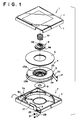
- a magnetic tape cartridge 1 in accordance with an embodiment of the present invention comprises a single reel 4 around which a magnetic tape 20 is wound and is contained for rotation in a cartridge casing 7.
- the reel 4 is formed by bonding together a lower reel half 5 and an upper reel half 6 by ultrasonic welding.
- the cartridge casing 7 is formed by fastening together upper and lower casing halves 2 and 3 by screws and the like.
- the lower reel half 5 comprises a cylindrical hub 23 and a flange 24 which are integrally molded from synthetic resin.
- a reel plate 8 for magnetically connecting a drive mechanism of a recording and reproducing system is mounted on the outer bottom surface of the hub 23.
- a stopper gear 23A which is brought into engagement with a brake gear 9A formed on a brake button 9 and prevents rotation of the reel 4 when the magnetic tape cartridge 1 is not used.
- the hub 23 is provided with an opening 23B, through which a brake release spindle in the recording and reproducing system is inserted to push upward the brake button 9.
- the brake button 9 is provided with said brake gear 9A at the lower end thereof and with a groove 9B at the upper end thereof.
- the groove 9B receives a guide projection (not shown).
- the brake button 9 is urged downward by a coiled spring 10 and is normally received in the hub 23, where the brake gear 9A and the stopper gear 23A are in mesh with each other to prevent rotation of the reel 4.
- the brake release spindle of the recording and reproducing system pushes upward the brake button 9, whereby the gears 9A and 23A are disengaged from each other to permit rotation of the reel 4.
- a tape outlet opening 26 through which the magnetic tape 20 is drawn out is formed in a side wall of the cartridge casing 7.
- the tape outlet opening 26 is closed and opened by a slide door 27 which is slidable in the directions of double-headed arrow A and is urged in the closing position by a spring not shown.
- a leader pin 21 is fixed to the leading end of the magnetic tape 20 and when the magnetic tape cartridge 1 is not used, the magnetic tape 20 is entirely wound around the reel 4 with the leader pin 21 held in a recess 28 formed near the tape outlet opening 26.
- the gears 23A and 9A of the hub 23 and the brake button 9 are disengaged from each other to permit rotation of the reel 4 in the manner described above and the drive mechanism of the recording and reproducing system holds the reel plate 8 under magnetic force and rotates the reel 4.
- the slide door 27 is opened and the leader pin 21 is brought to a predetermined position in a tape running path, thereby recording or reproduction becomes feasible.
- a non-contact type memory element (memory in cartridge) 30 (will be abbreviated as "MIC”, hereinbelow) for recording the contents of the information recorded on the magnetic tape and the like is provided in a corner 7A of the cartridge casing 7.
- the MIC 30 is like a rectangular plate as shown in Figure 2 in this particular embodiment, and information is recorded on and read out from the MIC 30 by a non-contact system such as electromagnetic induction.
- the MIC 30 has a recording surface 30A on which the information is recorded, upper and lower end faces 30B and 30C and left and right side faces 30D and 30E.
- the MIC 30 is mounted in the corner 7A of the cartridge casing 7 with the recording surface 30A held at 45° to the bottom surface of the cartridge casing 7.
- the MIC 30 is held with the recording surface 30A faced upward. Accordingly, the recording surface 30A is referred to as “the upper surface 30A” and the surface 30F opposite to the recording surface 30A will be referred to as “the lower surface 30F”, hereinbelow.
- Figure 3 is a cross-sectional view taken along line I-I in Figure 1 in the assembled state of the magnetic tape cartridge 1 and shows a memory holding structure of a first example.
- the memory holding structure of the first example comprises a lower end face abutment portion 32 which is formed in the lower casing half 3 and abuts against the lower end face 30C of the MIC 30 and an upper end face abutment portion 31 which is formed in the upper casing half 2 and abuts against the upper end face 30B of the MIC 30.
- the lower end face abutment portion 32 is formed on the bottom surface 3B of the lower casing half 3 and comprises a recess 33 which extends in parallel to a side wall 3A of the lower casing half 3 in a length substantially equal to the length of the major side of the MIC 30 and a protrusion 34 which projects inward from the recess 33.
- the recess 33 is a right triangle in cross-section and has end faces 33a and 33b.
- One inclined surface of the recess 33 smoothly merges with a surface of the protrusion 34 and forms a flat surface 32a which is at substantially 45° to the bottom surface of the lower casing half 2.
- the surface 32a supports the lower end face 30C of the MIC 30 and the end faces 33a and 33b of the recess 33 hold the side faces 30D and 30E of the MIC 30.
- the other inclined surface of the recess 33 supports the lower surface of the MIC 30.
- the upper end face abutment portion 31 is formed on a lower end portion of a block which extends inward from a side wall 2A of the upper casing half 2 and comprises a recess which is a right triangle in cross-section and is formed in the lower surface of the block.
- the recess comprises opposed inclined surfaces 31a and 31b which are in contact respectively with the upper end face 30B of the MIC 30 and the upper surface 30A of the MIC 30 near the upper end face 30B.
- the MIC 30 is held in the cartridge casing 7 with the upper surface 30A held at 45° to the bottom surface 3B of the casing 7. Further since the end faces 33a and 33b are in contact with the side faces 30D and 30E of the MIC 30, the MIC 30 cannot move in the direction parallel to the side wall 3A, whereby positioning of the MIC 30 during incorporation of the MIC 30 in the cartridge casing 7 is facilitated.
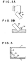
- the upper end face abutment portion 31 and the lower end face abutment portion 32 of the memory holding structure of the first example may be variously modified and for example may be as shown in Figures 5A and 5B, respectively. Further the upper end face abutment portion 31 may comprise a single inclined surface which is parallel to the inclined surface 32a ( Figure 4C) as shown in Figure 6. In the modification shown in Figure 6, since neither the upper end face abutment portion 31 nor the lower end face abutment portion 32 covers the upper surface 30A of the MIC 30, the MIC 30 can be provided with a semiconductor layer (recording area) over the entire area of the upper surface 30A.
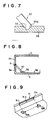
- lower end face abutment portion 32 may comprise only a recess 33 which extends in parallel to a side wall 3A of the lower casing half 3 in a length substantially equal to the length of the major side of the MIC 30 as shown in Figure 7.
- the upper end face abutment portion 31 can function also as a rib for reinforcing the upper casing half 2, whereby the structure of the cartridge casing is simplified and manufacture of the cartridge casing is facilitated.
- Figure 8 is a view similar to Figure 3 but showing a second example of the memory holding structure.
- the memory holding structure of the second example comprises a lower end face abutment portion 32 which is formed on the bottom of the lower casing half 3 and holds the lower end face 30C of the MIC 30 and an upper end face abutment portion 31 in the form of a recess which is formed in the lower casing half 3 at a portion where the lower casing half 3 is butted against the upper casing half 2 and abuts against the upper end face 30B of the MIC 30.
- the lower end face abutment portion 32 comprises a pair of L-shaped members 32A and 32B.
- the L-shaped member 32A is engaged with a part of the side face 30D and a part of the lower end face 30C of the MIC 30 and the L-shaped member 32B is engaged with a part of the side face 30E and a part of the lower end face 30C of the MIC 30.
- the upper end face abutment portion 31 in the form of the recess formed in the lower casing half 3 at a portion where the lower casing half 3 is butted against the upper casing half 2 extends along the side wall 3A in a length slight longer than the length of the MIC 30 and has a surface 31a in contact with the lower surface 30F of the MIC 30 near the upper end face 30B thereof and a pair of end faces 31b and 31c in contact respectively with the side faces 30D and 30E near the upper end face 30B thereof.
- the MIC 30 is held in the cartridge casing 7 with the upper surface 30A held at 45° to the bottom surface 3B of the casing 7. Further since the side faces 30D and 30E of the MIC 30 are held by the end faces 31b and 31c of the upper end face abutment portion 31 and the lower end face abutment portion 32, the MIC 30 cannot move in the direction parallel to the side wall 3A, whereby positioning of the MIC 30 during incorporation of the MIC 30 in the cartridge casing 7 is facilitated. Further since it is not necessary to form an additional member for holding the upper end face 30B of the MIC 30, the structure of the cartridge casing 7 is simplified and manufacture of the cartridge casing 7 is facilitated.
- the lower end face abutment portion 32 comprises a pair of L-shaped members 32A and 32B
- the lower end face abutment portion 32 may comprise only one of the L-shaped members 32A and 32B.
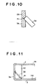
- the recess which forms the upper end face abutment portion 31 is entirely formed in the lower casing half 3, the recess may be formed partly in the lower casing half 3 and partly in the upper casing half 2 as shown in Figure 10.
- Figure 11 is a view similar to Figure 3 but showing a third example of the memory holding structure.
- the memory holding structure of the third example comprises a lower side face abutment portion 41 which is formed in the lower casing half 3 and snugly receives a part of the side faces 30D and 30E of the memory element 30 from below and an upper side face abutment portion 42 which is formed in the upper casing half 2 and snugly receives a part of the side faces 30D and 30E of the memory element 30 from above.
- the lower side face abutment portion 41 is formed in a corner between the side wall 3A and the bottom surface 3B of the lower casing half 3 and comprises a pair of support members 41A and 41B respectively having support surfaces 43A and 43B which are inclined at 45° to the bottom surface 3B of the lower casing half 3.
- the support surfaces 43A and 43B are respectively provided with recesses 45A and 45B which snugly receive the side faces 30D and 30E of the MIC 30 from below.
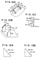
- the upper side face abutment portion 42 is formed in a corner between the side wall 2A (omitted in Figure 12B) and the top surface 2B of the upper casing half 2 and comprises a pair of support members 42A and 42B respectively having support surfaces 44A and 44B which are inclined at 45° to the top surface 2B of the upper casing half 2.
- the support surfaces 44A and 44B are respectively provided with recesses 46A and 46B which snugly receive the side faces 30D and 30E of the MIC 30 from above.
- each side face of the MIC 30 is snugly received partly in the recess 45A (45B) of the lower side face abutment portion 41 and partly in the recess 46A (46B) of the upper side face abutment portion 42 as shown in Figure 12C.
- the recesses 45A and 45B of the lower side face abutment portion 41 be of a shape such as those shown in Figures 13A and 13B which permits the lower casing half 3 to be easily ejected from a mold when molding the lower casing half 3.
- the recesses 46A and 46B of the upper side face abutment portion 42 be of a shape such which permits the upper casing half 2 to be easily ejected from a mold when molding the upper casing half.
- the MIC 30 is held in the cartridge casing 7 with the upper surface 30A held at 45° to the bottom surface 3B of the casing 7. Further since the side faces 30D and 30E of the MIC 30 are snugly received in the recesses 45A, 45B, 46A and 46B, the MIC 30 cannot move in the direction parallel to the side wall 3A, whereby positioning of the MIC 30 during incorporation of the MIC 30 in the cartridge casing 7 is facilitated. Further since the upper and lower side face abutment portions 42 and 41 can function as ribs for reinforcing the upper and lower casing halves 2 and 3 and it is not necessary to form additional members for holding the MIC 30, the structure of the cartridge casing 7 is simplified and manufacture of the cartridge casing 7 is facilitated.
- the upper side face abutment portion 42 need not be provided with recesses 46A and 46B when the recesses 45A and 45B of the lower side face abutment portion 41 are substantially the same in depth as the thickness of the MIC 30.
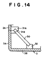
- the memory holding structure of the fourth example comprises a lower end face abutment portion 32 which is formed in the lower casing half 3 and abuts against the lower end face 30C of the MIC 30 and an upper end face abutment portion 31 which is formed in the upper casing half 2 and abuts against the upper end face 30B of the MIC 30.
- Both the upper and lower end face abutment portions 31 and 32 are formed of cushioning material.
- the lower end face abutment portion 32 is in the form a block which is of cushioning material and extends inward from the bottom surface 3B of the lower casing half 3.
- the block is provided with a recess which extends in parallel to the side wall 3A of the lower casing half 3 in a length substantially equal to the length of the major side of the MIC 30.
- the recess receives the lower end face 30C of the MIC 30 and a portion of the lower surface 30F near the lower end face 30C; whereby the lower end face abutment portion 32 holds the MIC 30 away from the bottom of the cartridge casing 7.
- the upper end face abutment portion 31 is formed on blocks 31A and 31B which are of cushioning material and extend inward respectively from the side wall 2A of the upper casing half 2 and the side wall 3A of the lower casing half 3A.
- the block 31A is provided with a recess which receives the upper end face 30B of the MIC 30 and a portion of the upper surface 30A near the upper end face 30B, and the block 31B has an inclined surface which abuts against the lower surface 30F of the MIC 30 at a portion near the upper end face 30B, whereby the upper end face abutment portion 31 holds the MIC 30 away from the side walls 2A and 3A of the cartridge casing 7.
- the MIC 30 is held in the cartridge casing 7 with the upper surface 30A held at 45° to the bottom surface 3B of the casing 7. Further since the upper and lower end face abutment portions 31 and 32 are both formed of a cushioning material and holds the MIC 30 away from the inner surface of the cartridge casing 7, the MIC 30 can be protected from impact applied to the cartridge casing 7 from outside and prevented from being damaged by vibration of the casing 7 or when the magnetic tape cartridge 1 is dropped. Stopper members which abut against the side faces 30D and 30E of the MIC 30 may be provided in order to prevent the MIC 30 from moving sideways when the memory holding structure does not abut against the side faces 30D and 30E as in the fourth example.
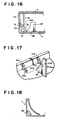
- the upper end face abutment portion 31 and the lower end face abutment portion 32 of the memory holding structure of the fourth example may be variously modified and for example may be as shown in Figure 15A. Further as shown in Figures 15B and 15C, a block 32B which abuts against the entire area of the lower surface 30C of the MIC 30 may be provided. Further the upper and lower end face abutment portions may be integrated into a holding member 35 as shown in Figure 15D.
- Figure 16 is a view similar to Figure 3 but showing a fifth example of the memory holding structure.
- the memory holding structure of the fifth example comprises an upper end face abutment portion 31 which is formed in the lower casing half 3 and abuts against the upper end face 30B of the MIC 30, an upper surface abutment portion 36 which is formed in the upper casing half 2 and abuts against the upper surface 30A of the MIC 30 and a lower surface abutment portion 37 which is formed in the lower casing half 3 and abuts against the lower surface 30F of the MIC 30.
- the lower casing half 3 is further provided with a guide plate 50 which guides the lower end face 30C of the MIC 30.
- the upper end face abutment portion 31 comprises a pair of support posts 31A and 31B each of which is projected inward from the side wall 3A of the lower casing half 3 and is provided with an inclined surface which supports the lower surface 30F of the MIC 30 at a portion near the upper end face 30B.
- the lower surface abutment portion 37 comprises a pair of support posts 37A and 37B each of which extends upward from the bottom of the lower casing half 3 and is provided with an inclined surface which supports the lower surface 30F of the MIC 30 from below.
- the upper surface abutment portion 36 extends downward from the top surface 2B of the upper casing half 2 is provided with an inclined surface 36a which abuts against the upper surface 30A of the MIC 30 from above.
- the guide plate 50 extends upward from the bottom of the lower casing half 3 substantially at the middle between the support posts 37A and 37B and is provided with an arcuate surface 50a which guides the MIC 30 dropped toward the abutment portions 31 and 37 to the position where it is supported by the abutment portions 31 and 37.
- the MIC 30 can be positioned at 45° to the bottom surface 3B of the cartridge casing 7. Further in the assembled state, the upper surface abutment portion 36 presses the MIC 30 from above to surely hold the MIC 30 in a position where the upper surface 30A is held at 45° to the bottom surface 3B of the cartridge casing 7.
- the lower surface abutment portion 37 may comprise a single block which is provided with an inclined surface which abuts against the lower surface 30F of the MIC 30 over the entire area thereof. Further the arcuate surface 50a of the guide plate 50 may have a width substantially equal to the major length of the MIC 30 so that the entire length of the lower end face 30C of the MIC 30 is guided by the arcuate surface 50a.
- the surfaces in contact with the MIC 30 may be provided with a cushioning material.
- the MIC 30 may be bonded to the memory holding structure by adhesive.
- the MIC 30 may be held so that the upper and lower end faces 30B and 30C are held at 45° to the side walls 2A and 3A as shown in Figure 18. Further the MIC 30 may be held in any place so long as it does not interfere with rotation of the reel 4.
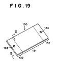
- Figure 19 shows a MIC 130 which is employed together with the memory holding structures of the sixth to eighth examples.
- the recording surface (upper surface) of the MIC 130 has a recording area 131 at the middle thereof and a pair of non-recording areas 132 on opposite sides of the recording area 131.
- the recording area 131 is an area actually used for recording information.
- Each non-recording area 132 is provided with a through hole 133.
- a post-like projection is press-fitted in the through hole, thereby holding the MIC 130 with its upper surface held at 45° to the bottom surface of the lower casing half 3.
- the through 133 may be of various shapes and the shape of the post-like projection is selected according to the shape of the through hole 133.
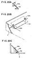
- the MIC 130 is provided with a pair of through holes 133a each of which is a straight hole whose inner peripheral surface is inclined at 45° to the upper and lower surfaces of the MIC 130 over the entire circumference.
- a pair of cylindrical post-like projections 103A are erected from the bottom of the lower casing half 3 as shown in Figures 20B and 20C.
- Each post-like projection 103A has a tip portion having a smaller diameter and a support shoulder inclined at 45° to the bottom surface of the lower casing half 3 is formed at the base of the tip portion.
- the tip portion of the post-like projection 103A is press-fitted in the through hole 133a so that the lower surface of the MIC 130 rests on the inclined support shoulder as clearly shown in Figure 20C, whereby the MIC 130 is held with its upper surface inclined at 45° to the bottom surface of the lower casing half 3.
- the inclined support shoulder may be omitted.
- the MIC 130 is positioned by bringing the upper and lower ends of the MIC 130 into abutment respectively against the side wall and the bottom wall of the lower casing half 3.
- the MIC 130 is provided with a pair of through holes 133b.
- Each through hole 133b has an inner peripheral surface which is partly vertical to the surfaces of the MIC 130 and partly inclined at 45° to the surfaces of the MIC 130.
- a pair of post-like projections 103B are erected from the bottom of the lower casing half 3 as shown in Figure 21B.
- the outer peripheral surface of each post-like projection 103B is vertical to the bottom surface of the cartridge casing 7 and a surface inclined at 45° to the bottom surface of the cartridge casing 7 is formed near the top of the post-like projection 103B.
- the tip portion of the post-like projection 103B is press-fitted in the through hole 133b so that the part of the inner peripheral surface of the through hole 133b rests on the inclined surface of the post-like projection 103B as shown in Figure 21B, whereby the MIC 130 is held with its upper surface inclined at 45° to the bottom surface of the cartridge casing 7.
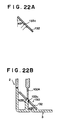
- the MIC 130 is provided with a pair of through holes 133c whose inner peripheral surface is vertical to the upper and lower surfaces of the MIC 130 over the entire circumference.
- a pair of post-like projections 103C which are similar to those 103B employed in the seventh example can be employed.
- the MIC 130 is held with its upper surface inclined at 45° to the bottom surface of the cartridge casing 7 as shown in Figure 22B.
- a pair of retainer ribs 102A are provided on the upper casing half 2 so that the lower ends of the retainer ribs 102A abut against the top surfaces of the post-like projections 103C as shown in Figure 22B.
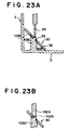
- the post-like projection 103C may be provided with a support shoulder 103S which is inclined at 45° to the bottom surface of the cartridge casing 7 and supports the lower surface of the MIC 130 from below as shown in Figure 23A.
- the retainer rib 102A may be provided with an abutment surface 102S which is inclined at 45° to the bottom surface of the cartridge casing 7 and abuts against the upper surface of the MIC 130 as shown in Figure 23B.
- the eighth example in which the through holes 133c are vertical to the surfaces of the MIC 130 is most advantageous from the viewpoint of facility of manufacturing the MIC 130.
- the through holes 133c can be formed simultaneously with molding of the body of the MIC 130.
- the latter two examples are advantageous over the former in that the MIC 130 can be held more stably.
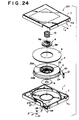
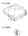
- FIG 24 shows the magnetic tape cartridge 101 of this embodiment.
- the magnetic tape cartridge 101 of this embodiment is substantially the same in structure as the magnetic tape cartridge 1 shown in Figure 1 except that an engagement recess 7a is formed on the front face of the cartridge casing 7. Accordingly the elements analogous to those shown in Figure 1 are given the same reference numerals and will not be described here.
- reference numeral 27a denotes a spring for urging the slide door 27 toward the closing position.
- Arrow Y indicates the direction of insertion of the magnetic tape cartridge 101 into a recording and reproducing system which is equal to the direction in which the slide door 26 is slid to close the tape outlet opening 26. When opening the tape outlet opening 26, the slide door is slid in the direction of arrow Y'.
- the engagement recess 7a is formed partly in the upper casing half 2 and partly in the lower casing half 3, and when the upper and lower casing halves 2 and 3 are mated together, a conical engagement recess 7a is formed.
- a stopper 110 in the form of a conical projection in the recording and reproducing system is brought into engagement with the engagement recess 7a as shown in Figure 25B.
- the gears 23A and 9A of the hub 23 and the brake button 9 are disengaged from each other to permit rotation of the reel 4 in the manner described above and the drive mechanism of the recording and reproducing system holds the reel plate 8 under magnetic force and rotates the reel 4.
- the slide door 27 is opened overcoming the force of the spring 27a and the leader pin 21 is brought to a predetermined position in a tape running path, thereby recording or reproduction becomes feasible.
- the wall surface defining the space in the recording and reproducing system is at a space from the outer surface of the magnetic tape cartridge 101 and the space permits the magnetic tape cartridge 101 to be rotated under the turning moment R.
- the ejection mechanism of the recording and reproducing system cannot properly grip the magnetic tape cartridge 101 and a corner portion K of the magnetic tape cartridge 101 can abut against the inner wall of the space when the magnetic tape cartridge 101 is ejected from the recording and reproducing system, which can obstruct ejection of the magnetic tape cartridge 101.
- the magnetic tape cartridge 101 is provided with a conical engagement recess 7a
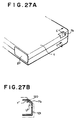
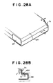
- the magnetic tape cartridge 101 may be provided with an engagement recess of various shapes according to the shape of the stopper of the recording and reproducing system.
- the magnetic tape cartridge 101 may be provided with an engagement recess 7b or 7c shown in Figures 27A and 28A depending on the shape of the stopper 120 and 130 shown in Figures 27B and 28B.
Landscapes
- Packaging Of Annular Or Rod-Shaped Articles, Wearing Apparel, Cassettes, Or The Like (AREA)
- Packages (AREA)
Priority Applications (1)
| Application Number | Priority Date | Filing Date | Title |
|---|---|---|---|
| EP00120847A EP1067549B1 (fr) | 1997-12-18 | 1998-12-17 | Cassette de bande magnetique |
Applications Claiming Priority (4)
| Application Number | Priority Date | Filing Date | Title |
|---|---|---|---|
| JP34892397 | 1997-12-18 | ||
| JP34892397 | 1997-12-18 | ||
| JP6097398 | 1998-03-12 | ||
| JP10060973A JPH11238334A (ja) | 1997-12-18 | 1998-03-12 | 磁気テープカートリッジ |
Related Child Applications (1)
| Application Number | Title | Priority Date | Filing Date |
|---|---|---|---|
| EP00120847A Division EP1067549B1 (fr) | 1997-12-18 | 1998-12-17 | Cassette de bande magnetique |
Publications (3)
| Publication Number | Publication Date |
|---|---|
| EP0924701A2 true EP0924701A2 (fr) | 1999-06-23 |
| EP0924701A3 EP0924701A3 (fr) | 1999-09-08 |
| EP0924701B1 EP0924701B1 (fr) | 2003-04-09 |
Family
ID=26402028
Family Applications (2)
| Application Number | Title | Priority Date | Filing Date |
|---|---|---|---|
| EP98124033A Expired - Lifetime EP0924701B1 (fr) | 1997-12-18 | 1998-12-17 | Cassette à bande magnétique |
| EP00120847A Expired - Lifetime EP1067549B1 (fr) | 1997-12-18 | 1998-12-17 | Cassette de bande magnetique |
Family Applications After (1)
| Application Number | Title | Priority Date | Filing Date |
|---|---|---|---|
| EP00120847A Expired - Lifetime EP1067549B1 (fr) | 1997-12-18 | 1998-12-17 | Cassette de bande magnetique |
Country Status (4)
| Country | Link |
|---|---|
| US (2) | US6452745B1 (fr) |
| EP (2) | EP0924701B1 (fr) |
| JP (1) | JPH11238334A (fr) |
| DE (2) | DE69813907T2 (fr) |
Cited By (11)
| Publication number | Priority date | Publication date | Assignee | Title |
|---|---|---|---|---|
| EP1104929A1 (fr) * | 1998-07-17 | 2001-06-06 | Fuji Photo Film Co., Ltd. | Cassette de bande magnetique |
| US6299088B1 (en) | 1999-12-30 | 2001-10-09 | Imation Corp. | Memory chip retainer for a data storage cartridge |
| EP1168340A2 (fr) * | 2000-06-26 | 2002-01-02 | Fuji Photo Film Co., Ltd. | Cassette à bande magnétique |
| US6345779B1 (en) | 1999-12-31 | 2002-02-12 | Imation Corp. | Data storage cartridge having a retainer for a leader pin |
| US6505789B2 (en) | 2000-12-22 | 2003-01-14 | Imation Corp. | Data storage cartridge having a two-sided retainer spring for a leader pin |
| EP1331640A1 (fr) * | 2000-11-02 | 2003-07-30 | Sony Corporation | Cartouche de bande monobobine et dispositif d'enregistrement et de reproduction dans lequel ladite cartouche est utilisee |
| US6628479B1 (en) | 2000-09-28 | 2003-09-30 | Imation Corp. | Door assembly for a data storage cartridge |
| US6650504B2 (en) | 2001-05-09 | 2003-11-18 | Imation Corp. | Data storage tape cartridge with tape reel centering brake assembly |
| US6900964B2 (en) | 2002-02-21 | 2005-05-31 | International Business Machines Corporation | Data-cartridge case adapted for dual-format applications |
| US7064926B2 (en) | 2001-06-22 | 2006-06-20 | Fuji Photo Film Co., Ltd. | Cartridge case with chip retaining features |
| EP1154430A3 (fr) * | 2000-05-11 | 2006-08-02 | Fuji Photo Film Co., Ltd. | Cassette pour support d'enregistrement et étiquette de cassette |
Families Citing this family (19)
| Publication number | Priority date | Publication date | Assignee | Title |
|---|---|---|---|---|
| JP2002008342A (ja) | 2000-06-26 | 2002-01-11 | Fuji Photo Film Co Ltd | 磁気テープカートリッジ |
| JP4146624B2 (ja) * | 2001-05-28 | 2008-09-10 | 富士フイルム株式会社 | 磁気テープカートリッジのリーダピン脱着力測定器 |
| JP2003157655A (ja) * | 2001-11-20 | 2003-05-30 | Fuji Photo Film Co Ltd | 記録テープカートリッジ |
| JP3808777B2 (ja) | 2002-01-18 | 2006-08-16 | 富士写真フイルム株式会社 | 記録テープカートリッジ |
| JP2003297040A (ja) * | 2002-03-29 | 2003-10-17 | Fuji Photo Film Co Ltd | 記録テープカートリッジ |
| JP4000279B2 (ja) * | 2002-05-29 | 2007-10-31 | 富士フイルム株式会社 | 記録テープカートリッジ |
| US6702215B2 (en) * | 2002-07-03 | 2004-03-09 | Quantum Corporation | Repositionable memory element in a single reel tape cartridge |
| JP4167018B2 (ja) * | 2002-07-10 | 2008-10-15 | 富士フイルム株式会社 | 記録テープカートリッジ |
| US7038874B1 (en) | 2003-05-19 | 2006-05-02 | International Business Machines Corporation | Tamper resistant write once recording of a data storage cartridge having rewritable media |
| JP2005182880A (ja) * | 2003-12-17 | 2005-07-07 | Fuji Photo Film Co Ltd | テープカートリッジ |
| US20050152670A1 (en) * | 2004-01-14 | 2005-07-14 | Quantum Corporation | Auxiliary memory in a tape cartridge |
| US7156335B2 (en) * | 2004-10-28 | 2007-01-02 | Quantum Corporation | Mam assembly process and features |
| JP2007004938A (ja) * | 2005-06-27 | 2007-01-11 | Fujifilm Holdings Corp | 磁気テープカートリッジ |
| JP4795913B2 (ja) * | 2006-11-06 | 2011-10-19 | 富士フイルム株式会社 | 磁気テープカートリッジ用ケース、及び磁気テープカートリッジ |
| JP4819011B2 (ja) * | 2007-09-04 | 2011-11-16 | 富士フイルム株式会社 | 記録テープカートリッジ |
| JP4846748B2 (ja) * | 2008-03-10 | 2011-12-28 | 富士フイルム株式会社 | 記録テープカートリッジ |
| US10984819B2 (en) * | 2018-04-09 | 2021-04-20 | Sony Corporation | Magnetic tape recording device including cartridge memory having a plurality of memory banks |
| JP7266547B2 (ja) * | 2020-03-23 | 2023-04-28 | 富士フイルム株式会社 | 記録テープカートリッジ |
| JP7209664B2 (ja) | 2020-03-23 | 2023-01-20 | 富士フイルム株式会社 | 記録テープカートリッジ |
Citations (5)
| Publication number | Priority date | Publication date | Assignee | Title |
|---|---|---|---|---|
| WO1993021633A1 (fr) * | 1992-04-17 | 1993-10-28 | Minnesota Mining And Manufacturing Company | Element de stockage de donnees polyvalent a identification automatique |
| DE4214446A1 (de) * | 1992-05-06 | 1993-11-11 | Thomson Brandt Gmbh | Kassette mit einem Aufzeichnungsträger und einem Halbleiterspeicher |
| WO1995006944A1 (fr) * | 1993-09-01 | 1995-03-09 | Storage Technology Corporation | Dispositif universel auto-identifiable de stockage des donnees muni d'un mecanisme de protection contre l'ecriture comprehensible par l'homme |
| EP0677845A2 (fr) * | 1994-04-13 | 1995-10-18 | Minnesota Mining And Manufacturing Company | Elément et système de stockage de données |
| WO1997045837A1 (fr) * | 1996-05-30 | 1997-12-04 | Quantum Corporation | Systeme de cartouche pour bande magnetique a memoire d'etat de la cartouche |
Family Cites Families (9)
| Publication number | Priority date | Publication date | Assignee | Title |
|---|---|---|---|---|
| GB1406084A (en) * | 1971-09-17 | 1975-09-10 | Sony Corp | Cartridge for use in magnetic recording and or reproducing apparatus |
| JPS5228311A (en) * | 1975-08-29 | 1977-03-03 | Nippon I B M Kk | Tape cartridge with selflock function shutter |
| US4559575A (en) * | 1982-11-22 | 1985-12-17 | Dysan Corporation | Removable disk cartridge with improved door operating mechanism |
| US4945530A (en) * | 1986-11-14 | 1990-07-31 | Opticord, Inc. | Cartridge for optical data discs |
| JPH0536678U (ja) | 1991-10-15 | 1993-05-18 | 富士写真フイルム株式会社 | 磁気テープカートリツジ |
| US5610789A (en) | 1995-05-09 | 1997-03-11 | Eastman Kodak Company | Tape cartridge with a gate member slidably mounted an access door |
| JP3695921B2 (ja) * | 1997-12-22 | 2005-09-14 | 富士写真フイルム株式会社 | 磁気テープカートリッジ |
| JP3658516B2 (ja) * | 1998-03-16 | 2005-06-08 | 日立マクセル株式会社 | 記録媒体用カートリッジ |
| US6299088B1 (en) * | 1999-12-30 | 2001-10-09 | Imation Corp. | Memory chip retainer for a data storage cartridge |
-
1998
- 1998-03-12 JP JP10060973A patent/JPH11238334A/ja active Pending
- 1998-12-16 US US09/212,484 patent/US6452745B1/en not_active Expired - Lifetime
- 1998-12-17 DE DE69813907T patent/DE69813907T2/de not_active Expired - Lifetime
- 1998-12-17 EP EP98124033A patent/EP0924701B1/fr not_active Expired - Lifetime
- 1998-12-17 EP EP00120847A patent/EP1067549B1/fr not_active Expired - Lifetime
- 1998-12-17 DE DE69813163T patent/DE69813163T2/de not_active Expired - Lifetime
-
2002
- 2002-03-14 US US10/096,656 patent/US6481658B1/en not_active Expired - Fee Related
Patent Citations (5)
| Publication number | Priority date | Publication date | Assignee | Title |
|---|---|---|---|---|
| WO1993021633A1 (fr) * | 1992-04-17 | 1993-10-28 | Minnesota Mining And Manufacturing Company | Element de stockage de donnees polyvalent a identification automatique |
| DE4214446A1 (de) * | 1992-05-06 | 1993-11-11 | Thomson Brandt Gmbh | Kassette mit einem Aufzeichnungsträger und einem Halbleiterspeicher |
| WO1995006944A1 (fr) * | 1993-09-01 | 1995-03-09 | Storage Technology Corporation | Dispositif universel auto-identifiable de stockage des donnees muni d'un mecanisme de protection contre l'ecriture comprehensible par l'homme |
| EP0677845A2 (fr) * | 1994-04-13 | 1995-10-18 | Minnesota Mining And Manufacturing Company | Elément et système de stockage de données |
| WO1997045837A1 (fr) * | 1996-05-30 | 1997-12-04 | Quantum Corporation | Systeme de cartouche pour bande magnetique a memoire d'etat de la cartouche |
Cited By (20)
| Publication number | Priority date | Publication date | Assignee | Title |
|---|---|---|---|---|
| EP1104929A4 (fr) * | 1998-07-17 | 2004-03-31 | Fuji Photo Film Co Ltd | Cassette de bande magnetique |
| EP1104929A1 (fr) * | 1998-07-17 | 2001-06-06 | Fuji Photo Film Co., Ltd. | Cassette de bande magnetique |
| US6299088B1 (en) | 1999-12-30 | 2001-10-09 | Imation Corp. | Memory chip retainer for a data storage cartridge |
| US6345779B1 (en) | 1999-12-31 | 2002-02-12 | Imation Corp. | Data storage cartridge having a retainer for a leader pin |
| US7301728B2 (en) | 2000-05-11 | 2007-11-27 | Fujifilm Corporation | Recording medium cartridge having an accommodation portion for a noncontact-type memory |
| US7126791B2 (en) | 2000-05-11 | 2006-10-24 | Fuji Photo Film Co., Ltd. | Recording medium cartridge having an accommodation portion for a noncontact-type memory |
| EP1154430A3 (fr) * | 2000-05-11 | 2006-08-02 | Fuji Photo Film Co., Ltd. | Cassette pour support d'enregistrement et étiquette de cassette |
| EP1168340A3 (fr) * | 2000-06-26 | 2003-04-23 | Fuji Photo Film Co., Ltd. | Cassette à bande magnétique |
| US6820832B2 (en) | 2000-06-26 | 2004-11-23 | Fuji Photo Film Co., Ltd. | Magnetic tape cartridge |
| EP1589537A2 (fr) * | 2000-06-26 | 2005-10-26 | Fuji Photo Film Co., Ltd | Cassette à bande magnétique |
| EP1589537A3 (fr) * | 2000-06-26 | 2006-02-01 | Fuji Photo Film Co., Ltd | Cassette à bande magnétique |
| US6598820B2 (en) | 2000-06-26 | 2003-07-29 | Fuji Photo Film Co., Ltd. | Magnetic tape cartridge |
| EP1168340A2 (fr) * | 2000-06-26 | 2002-01-02 | Fuji Photo Film Co., Ltd. | Cassette à bande magnétique |
| US6628479B1 (en) | 2000-09-28 | 2003-09-30 | Imation Corp. | Door assembly for a data storage cartridge |
| EP1331640A1 (fr) * | 2000-11-02 | 2003-07-30 | Sony Corporation | Cartouche de bande monobobine et dispositif d'enregistrement et de reproduction dans lequel ladite cartouche est utilisee |
| EP1331640A4 (fr) * | 2000-11-02 | 2007-10-24 | Sony Corp | Cartouche de bande monobobine et dispositif d'enregistrement et de reproduction dans lequel ladite cartouche est utilisee |
| US6505789B2 (en) | 2000-12-22 | 2003-01-14 | Imation Corp. | Data storage cartridge having a two-sided retainer spring for a leader pin |
| US6650504B2 (en) | 2001-05-09 | 2003-11-18 | Imation Corp. | Data storage tape cartridge with tape reel centering brake assembly |
| US7064926B2 (en) | 2001-06-22 | 2006-06-20 | Fuji Photo Film Co., Ltd. | Cartridge case with chip retaining features |
| US6900964B2 (en) | 2002-02-21 | 2005-05-31 | International Business Machines Corporation | Data-cartridge case adapted for dual-format applications |
Also Published As
| Publication number | Publication date |
|---|---|
| EP1067549A3 (fr) | 2001-03-07 |
| DE69813163D1 (de) | 2003-05-15 |
| US6452745B1 (en) | 2002-09-17 |
| DE69813907T2 (de) | 2003-11-06 |
| EP1067549A2 (fr) | 2001-01-10 |
| EP0924701A3 (fr) | 1999-09-08 |
| DE69813907D1 (de) | 2003-05-28 |
| DE69813163T2 (de) | 2003-10-23 |
| JPH11238334A (ja) | 1999-08-31 |
| EP0924701B1 (fr) | 2003-04-09 |
| US6481658B1 (en) | 2002-11-19 |
| EP1067549B1 (fr) | 2003-04-23 |
Similar Documents
| Publication | Publication Date | Title |
|---|---|---|
| EP0924701A2 (fr) | Cassette à bande magnetique | |
| EP0924702B1 (fr) | Cassette à bande magnétique | |
| KR100427468B1 (ko) | 카세트 수납 케이스 | |
| US6118751A (en) | Disk cartridge, disk drive and disk changer apparatus using the disk cartridge, and method for handling the disk cartridge | |
| EP1569232A2 (fr) | Cassette à bande d'enregistrement | |
| KR100450452B1 (ko) | 자기 테이프 카트리지 | |
| US6742738B2 (en) | Recording tape cartridge | |
| EP2011119B1 (fr) | Cartouche à disque | |
| US6974101B2 (en) | Recording tape cartridge | |
| US7218477B2 (en) | Information recording medium cartridge | |
| US6845935B2 (en) | Recording tape cartridge | |
| US6988686B2 (en) | Recording tape cartridge | |
| JP2916799B2 (ja) | ディスクカートリッジ | |
| US7004418B2 (en) | Recording tape cartridge | |
| US6840473B2 (en) | Recording tape cartridge | |
| EP0537678B1 (fr) | Boîtier d'emmagasinage de cassette à bande magnétique | |
| US6239949B1 (en) | Case for accommodating disc cartridge | |
| JP4368834B2 (ja) | 磁気テープカートリッジ | |
| JP4602470B2 (ja) | 磁気テープカートリッジ | |
| US6894872B2 (en) | Disk cartridge having shutter operation portions which do not obstruct access to a medium whether shutter members are at a closed position or an open position | |
| JP3881284B2 (ja) | 記録テープカートリッジ | |
| JP2002109848A (ja) | 磁気ディスクカートリッジ |
Legal Events
| Date | Code | Title | Description |
|---|---|---|---|
| PUAI | Public reference made under article 153(3) epc to a published international application that has entered the european phase |
Free format text: ORIGINAL CODE: 0009012 |
|
| AK | Designated contracting states |
Kind code of ref document: A2 Designated state(s): DE FR GB |
|
| AX | Request for extension of the european patent |
Free format text: AL;LT;LV;MK;RO;SI |
|
| PUAL | Search report despatched |
Free format text: ORIGINAL CODE: 0009013 |
|
| RIC1 | Information provided on ipc code assigned before grant |
Free format text: 6G 11B 23/04 A, 6G 11B 23/07 B, 6G 11B 33/10 B, 6G 11B 33/12 B |
|
| AK | Designated contracting states |
Kind code of ref document: A3 Designated state(s): AT BE CH CY DE DK ES FI FR GB GR IE IT LI LU MC NL PT SE |
|
| AX | Request for extension of the european patent |
Free format text: AL;LT;LV;MK;RO;SI |
|
| 17P | Request for examination filed |
Effective date: 19990927 |
|
| 17Q | First examination report despatched |
Effective date: 20000105 |
|
| AKX | Designation fees paid |
Free format text: DE FR GB |
|
| RIN1 | Information on inventor provided before grant (corrected) |
Inventor name: HEINZE, ROBERT, RALPH Inventor name: ALBRECHT, THOMAS, R. Inventor name: MCALLISTER, JEFFREY, S. Inventor name: MORITA, KIYOO C/O FUJI PHOTO FILM CO., LTD. Inventor name: SHIGA, HIDEAKI C/O FUJI PHOTO FILM CO., LTD. |
|
| GRAG | Despatch of communication of intention to grant |
Free format text: ORIGINAL CODE: EPIDOS AGRA |
|
| GRAG | Despatch of communication of intention to grant |
Free format text: ORIGINAL CODE: EPIDOS AGRA |
|
| GRAH | Despatch of communication of intention to grant a patent |
Free format text: ORIGINAL CODE: EPIDOS IGRA |
|
| GRAH | Despatch of communication of intention to grant a patent |
Free format text: ORIGINAL CODE: EPIDOS IGRA |
|
| GRAA | (expected) grant |
Free format text: ORIGINAL CODE: 0009210 |
|
| AK | Designated contracting states |
Designated state(s): DE FR GB |
|
| REG | Reference to a national code |
Ref country code: GB Ref legal event code: FG4D |
|
| ET | Fr: translation filed | ||
| PLBE | No opposition filed within time limit |
Free format text: ORIGINAL CODE: 0009261 |
|
| STAA | Information on the status of an ep patent application or granted ep patent |
Free format text: STATUS: NO OPPOSITION FILED WITHIN TIME LIMIT |
|
| 26N | No opposition filed |
Effective date: 20040112 |
|
| REG | Reference to a national code |
Ref country code: GB Ref legal event code: 732E |
|
| REG | Reference to a national code |
Ref country code: FR Ref legal event code: TP Ref country code: FR Ref legal event code: CD |
|
| REG | Reference to a national code |
Ref country code: FR Ref legal event code: PLFP Year of fee payment: 18 |
|
| REG | Reference to a national code |
Ref country code: FR Ref legal event code: PLFP Year of fee payment: 19 |
|
| REG | Reference to a national code |
Ref country code: FR Ref legal event code: PLFP Year of fee payment: 20 |
|
| PGFP | Annual fee paid to national office [announced via postgrant information from national office to epo] |
Ref country code: FR Payment date: 20171113 Year of fee payment: 20 Ref country code: DE Payment date: 20171212 Year of fee payment: 20 |
|
| PGFP | Annual fee paid to national office [announced via postgrant information from national office to epo] |
Ref country code: GB Payment date: 20171213 Year of fee payment: 20 |
|
| REG | Reference to a national code |
Ref country code: DE Ref legal event code: R071 Ref document number: 69813163 Country of ref document: DE |
|
| REG | Reference to a national code |
Ref country code: GB Ref legal event code: PE20 Expiry date: 20181216 |
|
| PG25 | Lapsed in a contracting state [announced via postgrant information from national office to epo] |
Ref country code: GB Free format text: LAPSE BECAUSE OF EXPIRATION OF PROTECTION Effective date: 20181216 |