EP0920714B2 - Appareil electrique ou electronique - Google Patents
Appareil electrique ou electronique Download PDFInfo
- Publication number
- EP0920714B2 EP0920714B2 EP98916916A EP98916916A EP0920714B2 EP 0920714 B2 EP0920714 B2 EP 0920714B2 EP 98916916 A EP98916916 A EP 98916916A EP 98916916 A EP98916916 A EP 98916916A EP 0920714 B2 EP0920714 B2 EP 0920714B2
- Authority
- EP
- European Patent Office
- Prior art keywords
- base part
- electrical
- housing
- electronic device
- circuit board
- Prior art date
- Legal status (The legal status is an assumption and is not a legal conclusion. Google has not performed a legal analysis and makes no representation as to the accuracy of the status listed.)
- Expired - Lifetime
Links
Images


Classifications
-
- G—PHYSICS
- G06—COMPUTING; CALCULATING OR COUNTING
- G06F—ELECTRIC DIGITAL DATA PROCESSING
- G06F1/00—Details not covered by groups G06F3/00 - G06F13/00 and G06F21/00
- G06F1/16—Constructional details or arrangements
- G06F1/18—Packaging or power distribution
- G06F1/183—Internal mounting support structures, e.g. for printed circuit boards, internal connecting means
- G06F1/184—Mounting of motherboards
-
- G—PHYSICS
- G06—COMPUTING; CALCULATING OR COUNTING
- G06F—ELECTRIC DIGITAL DATA PROCESSING
- G06F1/00—Details not covered by groups G06F3/00 - G06F13/00 and G06F21/00
- G06F1/16—Constructional details or arrangements
- G06F1/18—Packaging or power distribution
- G06F1/183—Internal mounting support structures, e.g. for printed circuit boards, internal connecting means
- G06F1/187—Mounting of fixed and removable disk drives
-
- H—ELECTRICITY
- H01—ELECTRIC ELEMENTS
- H01R—ELECTRICALLY-CONDUCTIVE CONNECTIONS; STRUCTURAL ASSOCIATIONS OF A PLURALITY OF MUTUALLY-INSULATED ELECTRICAL CONNECTING ELEMENTS; COUPLING DEVICES; CURRENT COLLECTORS
- H01R9/00—Structural associations of a plurality of mutually-insulated electrical connecting elements, e.g. terminal strips or terminal blocks; Terminals or binding posts mounted upon a base or in a case; Bases therefor
- H01R9/22—Bases, e.g. strip, block, panel
- H01R9/24—Terminal blocks
- H01R9/26—Clip-on terminal blocks for side-by-side rail- or strip-mounting
- H01R9/2625—Clip-on terminal blocks for side-by-side rail- or strip-mounting with built-in electrical component
- H01R9/2658—Clip-on terminal blocks for side-by-side rail- or strip-mounting with built-in electrical component with built-in data-bus connection
-
- H—ELECTRICITY
- H01—ELECTRIC ELEMENTS
- H01R—ELECTRICALLY-CONDUCTIVE CONNECTIONS; STRUCTURAL ASSOCIATIONS OF A PLURALITY OF MUTUALLY-INSULATED ELECTRICAL CONNECTING ELEMENTS; COUPLING DEVICES; CURRENT COLLECTORS
- H01R9/00—Structural associations of a plurality of mutually-insulated electrical connecting elements, e.g. terminal strips or terminal blocks; Terminals or binding posts mounted upon a base or in a case; Bases therefor
- H01R9/22—Bases, e.g. strip, block, panel
- H01R9/24—Terminal blocks
- H01R9/26—Clip-on terminal blocks for side-by-side rail- or strip-mounting
- H01R9/2675—Electrical interconnections between two blocks, e.g. by means of busbars
-
- H—ELECTRICITY
- H02—GENERATION; CONVERSION OR DISTRIBUTION OF ELECTRIC POWER
- H02B—BOARDS, SUBSTATIONS OR SWITCHING ARRANGEMENTS FOR THE SUPPLY OR DISTRIBUTION OF ELECTRIC POWER
- H02B1/00—Frameworks, boards, panels, desks, casings; Details of substations or switching arrangements
- H02B1/015—Boards, panels, desks; Parts thereof or accessories therefor
- H02B1/04—Mounting thereon of switches or of other devices in general, the switch or device having, or being without, casing
- H02B1/052—Mounting on rails
-
- H—ELECTRICITY
- H05—ELECTRIC TECHNIQUES NOT OTHERWISE PROVIDED FOR
- H05K—PRINTED CIRCUITS; CASINGS OR CONSTRUCTIONAL DETAILS OF ELECTRIC APPARATUS; MANUFACTURE OF ASSEMBLAGES OF ELECTRICAL COMPONENTS
- H05K7/00—Constructional details common to different types of electric apparatus
- H05K7/14—Mounting supporting structure in casing or on frame or rack
- H05K7/1462—Mounting supporting structure in casing or on frame or rack for programmable logic controllers [PLC] for automation or industrial process control
- H05K7/1468—Mechanical features of input/output (I/O) modules
-
- H—ELECTRICITY
- H05—ELECTRIC TECHNIQUES NOT OTHERWISE PROVIDED FOR
- H05K—PRINTED CIRCUITS; CASINGS OR CONSTRUCTIONAL DETAILS OF ELECTRIC APPARATUS; MANUFACTURE OF ASSEMBLAGES OF ELECTRICAL COMPONENTS
- H05K7/00—Constructional details common to different types of electric apparatus
- H05K7/14—Mounting supporting structure in casing or on frame or rack
- H05K7/1462—Mounting supporting structure in casing or on frame or rack for programmable logic controllers [PLC] for automation or industrial process control
- H05K7/1475—Bus assemblies for establishing communication between PLC modules
- H05K7/1478—Bus assemblies for establishing communication between PLC modules including a segmented bus
-
- H—ELECTRICITY
- H01—ELECTRIC ELEMENTS
- H01R—ELECTRICALLY-CONDUCTIVE CONNECTIONS; STRUCTURAL ASSOCIATIONS OF A PLURALITY OF MUTUALLY-INSULATED ELECTRICAL CONNECTING ELEMENTS; COUPLING DEVICES; CURRENT COLLECTORS
- H01R12/00—Structural associations of a plurality of mutually-insulated electrical connecting elements, specially adapted for printed circuits, e.g. printed circuit boards [PCB], flat or ribbon cables, or like generally planar structures, e.g. terminal strips, terminal blocks; Coupling devices specially adapted for printed circuits, flat or ribbon cables, or like generally planar structures; Terminals specially adapted for contact with, or insertion into, printed circuits, flat or ribbon cables, or like generally planar structures
- H01R12/70—Coupling devices
- H01R12/71—Coupling devices for rigid printing circuits or like structures
- H01R12/72—Coupling devices for rigid printing circuits or like structures coupling with the edge of the rigid printed circuits or like structures
- H01R12/721—Coupling devices for rigid printing circuits or like structures coupling with the edge of the rigid printed circuits or like structures cooperating directly with the edge of the rigid printed circuits
Definitions
- the invention relates to an electrical or electronic device for placement on a mounting rail, comprising a housing, with at least one printed circuit board arranged in the housing and with pointing in the longitudinal direction of the mounting rail contacts for a data and / or power bus connection with adjacent, placed on the mounting rail and corresponding Contacts having devices, wherein the housing is formed at least two parts and a circuit board receiving upper part and the contacts exhibiting base part are provided and wherein the upper part with the base part via a first latch and the base part with the support rail via a second lock are detachably connectable.
- An electrical or electronic device with a one-piece housing is made of DE 44 02 002 A1 known.
- the known electronic device it is such that it can be latched onto a standard mounting rail and is automatically contacted with adjacent electronic devices when snapped. This results in a bus connection via the plated-through electronic devices.
- An electrical or electronic device of the type mentioned is from the US 4,472,764 known. Due to the divisibility of the housing, this known device basically offers the possibility of removing the printed circuit board together with the upper part of the housing receiving the printed circuit board, without the bus connection realized via the base parts being interrupted or the external lines connected to the terminals of the housing having to be removed , A disadvantage of the known device that it is also due to the multi-part of the device - the housing consists not only of an upper part and a base part, but the base part is also formed in two parts and connected only via a separate mounting foot with the mounting rail - an unintentional interruption the data and / or power bus connection can occur if the upper part is removed from the base part and it also comes to a release of the base part of the mounting rail or if the fitter unintentionally releases the base part for removing the upper part.
- Object of the present invention is to provide an electrical or electronic device of the type mentioned in which an accidental release of the base part of the mounting rail can be safely excluded.
- the previously derived and indicated object is achieved by an electrical or electronic device with the features of claim 1.
- the embodiment of the invention now ensures that the second lock can not be solved before the first lock, since the upper part must first be removed in order to unlock the second lock at all. An unintentional interruption of the bus connection is thus excluded.
- the first and second locking are each designed as a latching connection, since such locking can be realized quickly and easily.
- a resilient latching arm is provided on the upper part, while on the base part to the latching arm corresponding latching hooks are provided.
- the upper part can be pivoted onto the base part, wherein the first locking device has a grip or engagement section on the latching arm for releasing the upper part from the base part, which is manually operable from the outside of the housing.
- the release of the upper part of the base part can be realized in this embodiment extremely simple by releasing only one locking connection.
- About the handle or engagement portion of the locking arm can be manually opened by hand or with the aid of a tool, such as a screwdriver.
- a second latchable lock for releasably connecting the base part is provided with the support rail. It is important here that the second lock is completely independent of the first lock, so that a release of the first lock can not unintentionally lead to a release of the second lock.
- the base part is aufschwenkbar on the mounting rail and the second locking a spring-loaded latch on the base part for one-sided Has locking the mounting rail.
- the bolt is arranged in the region of the underside of the base part and thus not accessible from the outside per se.
- To open the second lock is on the latch an actuating opening and on the top of the base part an insertion opening for a tool, such as a screwdriver, provided, wherein the actuating opening is arranged offset from the insertion so that moves when inserting the tool into the actuating and insertion opening of the bolt against the spring load and the base part is released.
- the insertion opening on the base part is accessible only when the upper part is removed.
- the circuit board is properly arranged in the housing, d. H. in any case, contacted correctly in a specified on the base part PCB receptacle with the contacts provided there and thus also ensures that the circuit board is removed when removing the upper part of the base part with, is also provided according to the invention that in the circuit board and in the upper part respectively corresponding openings for inserting at least one fixing device are provided from the outside of the housing.
- the fixing device is in the present case therefore exclusively by the insertion of the fixing device from the outside into the openings in the upper part and the circuit board. This insertion is only possible if the respective openings in the upper part and the circuit board are aligned. At aligned openings, the circuit board is then in the desired mounting and contacting position.
- the fixing device has at least one, but preferably two Einsteckschenkel, wherein the Einsteckschenkel at least one thickening is provided, can be achieved via which a good frictional engagement with the corresponding opening in the circuit board.
- the fixing device can also fulfill a further purpose, namely to serve for electrical connection. Frequently, namely to be attached to the circuit board supply contacts. This can easily be done with appropriate training on the fixing.
- the fixing device should have at least one terminal element in the form of a terminal. In this case, the Einsteckschenkel contacted with a conductor on the circuit board. The electrical or electronic device then has the function of a stackable terminal.
- the fixing device does not protrude laterally beyond the electrical or electronic device, it is provided in an advantageous embodiment that the fixing device is received in a corresponding receptacle in the upper part.
- the fixing device has at least one clamping element, that is to say for connecting supply contacts, at least one connection opening is provided in the upper part for insertion of the feed contact into the clamping element and at least one actuating opening for actuating the clamping element.
- the fixing device So that the fixing device is not subject to any mechanical stresses during use of the clamping element which could be transmitted to the printed circuit board, the fixing device has a leg protruding from the clamping element, from which the plug-in leg protrudes. A step is now provided on the leg, while in the receptacle there is a corresponding step-shaped slot in which the step of the leg bears against the housing. Any tensile or compressive load is thus absorbed by the housing and not transmitted to the circuit board.
- a cover for the receptacle is provided, which is detachably connected to the housing, preferably latched.
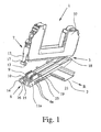
- an electrical or electronic device 1 is shown, which is provided for placement on a rail designed as DIN rail 2.
- the electrical or electronic device 1 itself has a housing 3, which consists of an insulating material, in particular plastic.
- a circuit board 4 is provided in a conventional manner with traces 5 on both sides of the circuit board and not shown electronic components.
- the electrical or electronic device 1 in the rail direction R facing as a knife contacts formed contacts 6a on one side 11a and corresponding, formed as a contact receiving contacts 6b on the other side 11b for a data and / or power bus connection for contacting adjacent, on the mounting rail 2 patch and corresponding contacts having further electronic devices.
- Electrical or electronic devices 1 of the type described above can be strung together on the basis of their training on a mounting rail 2, with a data and / or power bus connection results via the respective contacts 6a, 6b.
- the illustrated electrical or electronic device 1 is also designed in the manner of a stackable terminal and suitable in particular for the Ex-protection area.
- the housing 3 is formed at least in two parts.
- the housing 3 has a circuit board 4 receiving upper part 7 and the contacts 6a, 6b exhibiting base part 8.
- the base part 8 on a circuit board receptacle 9, which projects beyond the top 10 of the base part 8.
- the contacts in the printed circuit board receptacle 9 correspond to the contacts 6a, 6b in the sides 11a, 11b of the base part 8.
- a first latch For releasable connection of the upper part 7 with the base part 8, a first latch is provided, which is designed as a latching connection.
- the latching arm 12, which protrudes downward over the upper part 7, has a latching section 13, which cooperate with two corresponding latching hooks 14, 15 which are provided on the end face 16 of the base part 8.
- the latching hooks 14, 15 and the latching portion 13 each have chamfers in order to facilitate the latching.
- the two latching hooks 14, 15 are spaced apart, so that the latching arm is in the latched state between the latching hooks 14, 15.
- an engagement portion in the form of a pocket 17 is provided at the end of the latching arm 12, in which a tool, such as a screwdriver, used and with the aid of the latching arm 12 can be rebounded.
- the locking connection is provided, located on the other end face on the upper part 7, not shown receiving slot for a corresponding projection 18 on the base part 8, so that the upper part 7 is aufschwenkbar on the base part 8.
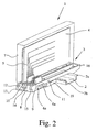
- a second locking is provided for releasable connection of the base part 8 with the support rail 2.
- a not-shown slot for engagement of the corresponding projection 2a of the support rail 2 is provided on the underside 20 of the base part 8.
- a spring-loaded latch 19 Opposite to the pivotal connection is located on the base part 8, a spring-loaded latch 19, which serves for one-sided engagement of the support rail 2 and the corresponding projection 2b of the support rail 2.
- the latch 19 is arranged on the underside 20 of the base part 8.
- the shape of the bolt 19 is approximately U-shaped, wherein the bolt 19 extends over the entire underside 20 of the base part 8.
- the upper ends of the U-legs are angled towards each other and each engage in a corresponding slot 21 on the sides 11a, 11b on the base part 8 a.
- the latch 21 is held captive on Sokkelteil 8.
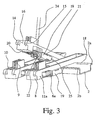
- On the latch 19 is an actuating opening 22, while in the base part 8 a continuous, accessible from the top 10 forth insertion opening 23 for a tool 24, such as a screwdriver, is provided (see, in particular Fig. 3 and 4 ).
- the insertion opening 23 is only accessible when the upper part 7 has been removed from the base part 8.
- the actuating opening 22 and the insertion opening 23 are offset from one another, wherein insertion of the tool 24 in the operating opening 22 but still possible.
- the actuating opening 22 opens into the insertion opening 23, wherein the latch 19 is moved against the spring load until the locking portion 25 no longer engages the corresponding projection 2b of the support rail 2 and the base part 8 thus of the support rail. 2 can be swung.
- the printed circuit board 4 itself is held in the housing 3 or in the upper part 7 of the housing 3 in a guide, which also facilitates the insertion of the printed circuit board 4 during installation.
- corresponding openings 26 are provided in the circuit board 4 and in the upper part 7, which serve forêten at least one fixing device 27 from the outside of the housing 3 ago.
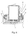
- fixators 27 is of course particularly advantageous in connection with the two-part housings 3 of the type according to the invention, the fixing means 27 may also be provided for fixing the circuit board 4 in a one-piece housing 3, as shown in FIG Fig. 6 is shown.
- the connection of the individual fixing devices 27 to the printed circuit board 4 takes place only via the insertion without a further connection, in particular a soldering is required.
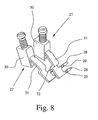
- the fixing device 27 in the in Fig. 5 embodiment illustrated a Einsteckschenkel 28, while in the in the Fig. 6 to 9 illustrated embodiments are each two Einsteckschenkel 28 per fixing device 27 are provided.
- the Einsteckschenkel 28 extend approximately at right angles to the plane of the circuit board 4 and thus coaxial with the DIN rail R. Since the individual Einsteckschenkel 28 are inserted only in the circuit board 4, to improve the connector at least one thickening 29 on Einsteckschenkel 28 is provided.
- a clamping element 30 is provided on the Einsteckschenkel 28 opposite end of the fixing device.
- illustrated terminal element 30 is in this case a screw terminal.
- the openings 27 are each in the range of conductor tracks 5, so that upon insertion of a Einsteckschenkels 28 results in a contact with the relevant interconnect 5.
- the existing in the terminal member 30 contact legs is led out of the terminal member 30 as legs 31. From the leg 31 are bent approximately at right angles to the Einsteckschenkel 28. Before the bending of the Einsteckschenkel 28 is on the leg 31, a step 32 is formed.
- the fixing devices 27 are respectively received in corresponding receptacles 33 in the housing 3 and in the upper part 7 of the housing 3.
- a connection opening is provided for each fixing device 27 and an actuating opening 35 is provided for actuating the clamping element 30.
- a corresponding step-shaped slot 36 is otherwise provided in the receptacle 33, in which the step 32 rests against the housing 3, so that any pressure and tensile loads are transmitted to the housing 3.
- the housing 3 or the upper part 7 has a cover 37 which can be detachably connected to the housing 3 or the upper part 7, in particular latched thereto.
Landscapes
- Engineering & Computer Science (AREA)
- Theoretical Computer Science (AREA)
- Power Engineering (AREA)
- General Physics & Mathematics (AREA)
- Computer Hardware Design (AREA)
- Human Computer Interaction (AREA)
- Physics & Mathematics (AREA)
- General Engineering & Computer Science (AREA)
- Microelectronics & Electronic Packaging (AREA)
- Automation & Control Theory (AREA)
- Developing Agents For Electrophotography (AREA)
- Mounting Components In General For Electric Apparatus (AREA)
- Coupling Device And Connection With Printed Circuit (AREA)
- Control And Other Processes For Unpacking Of Materials (AREA)
- Telephone Function (AREA)
- Mounting Of Printed Circuit Boards And The Like (AREA)
- Lubricants (AREA)
- Photoreceptors In Electrophotography (AREA)
Claims (10)
- Appareil (1) électrique au électronique destiné à être posé sur un rail support (2), comprenant un boîtier (3), avec au moins un circuit imprimé (4) disposé dans le boîtier (3) et des contacteurs (6a, 6b) orientés dans le sens longitudinal (R) du rail support (2) pour une connexion par bus de données et/ou d'énergie avec des appareils électrique au électronique voisins, posés sur le rail support (2) et présentant des contacteurs correspondants,
caractérisé en ce que
le boîtier (3) est conformé en au moins deux parties, une partie supérieure (7) recevant le circuit imprimé (4) ainsi qu'une partie formant embase (8) présentant les contacteurs (6a, 6b) étant prévues,
en ce que la partie supérieure (7) est susceptible d'être reliée avec la partie formant embase (8) par l'intermédiaire d'un premier verrouillage et la partie formant embase (8) est susceptible d'être reliée de façon amovible avec le rail support (2) par l'intermédiaire d'un second verrouillage,
en ce que le second verrouillage présente un verrou (19) soumis à une contrainte d'élasticité, maintenu en position coulissant le long de la partie formant embase (8) pour verrouiller d'un côté le rail support (2), et en ce que le verrou (19) est prévu dans la zone de la face inférieure (20) de la partie formant embase (8),
en ce que sont prévues sur le verrou (19) une ouverture d'actionnement (22) et sur la face supérieure (10) de la partie formant embase (8) une ouverture traversante d'introduction (23) pour un outil (24), accessible à partir de la face supérieure (10) de la partie ferment embase (8), et en ce que l'ouverture d'introduction (23) n'est accessible que dans le cas ou la partie supérieure (7) est enlevée, de telle sorte que le second verrouillage est susceptible d'être déverrouillé seulement après le déverrouillage du premier verrouillage et seulement après avoir enlevé ou séparé la partie supérieure (7) de la partie formant embase (8),
en ce que l'ouverture d'actionnement (22) est, dans l'état verrouillé de la partie formant embase (8), en position décalée par rapport à l'ouverture d'introduction (23), de telle sorte que l'ouverture d'actionnement (22) s'agrandit lors de l'introduction de l'outil (24), que le verrou (19) se déplace de manière antagoniste à la contrainte élastique et que la partie formant embase (8) soit débloquée,
et en ce que la partie ferment embase (8) est rabattable sur le rail support (2). - Appareil électrique ou électronique selon la revendication 1, caractérisé en ce que le premier et/ou le second verrouillage sont réalisés sous forme de liaison de blocage.
- Appareil électrique ou électrique selon la revendication 2, caractérisé en ce que le premier verrouillage présente une patte de blocage (12) élastique et des crochets de blocage (14, 15) en correspondance avec la patte de blocage (12), et en ce que de préférence sont prévus respectivement la patte de blocage (12) sur la partie supérieur (7) et les crochets de blocage (14, 15) sur la partie formant embase (8).
- Appareil électrique ou électronique selon l'une des revendications 1 à 3, caractérisé en ce que la partie supérieure (7) est rabattable sur la partie formant embase (8), et en ce que de préférence le premier verrouillage présente, sur la patte de blocages (12) une section de prise ou de mise en prise à manoeuvrer manuellement à partir de l'extérieur du boîtier (3), pour le déblocage de la partie supérieur (7) par rapport a la partie formant embase (8).
- Appareil électrique ou électronique selon l'une des revendications 1 à 4, caractérisé en ce que dans le circuit imprimé (4) et dans la partie supérieure (7), des ouvertures (26) correspondantes sont chaque fois prévues pour insérer au moins un dispositif de fixation (27) à partir de la face externe du boîtier (3) et en ce que de préférence le dispositif de fixation (27) pour la liaison avec le circuit imprimé (4) est uniquement inséré dans le circuit imprimé, sans autre liaison avec le circuit imprimé (4).
- Appareil électrique ou électronique selon la revendication 5, caractérisé en ce que le dispositif de fixation (27) présente au moins une, et de préférence deux, branches ou pattes d'insertion (28) orientées dans le sens longitudinal (R) du rail support (2), et en ce que de préférence sur la ou les branches d'insertion (28) un renfort ou surépaisseur (29) est prévu.
- Appareil électrique ou électronique selon la revendication 5 ou 6, caractérisé en ce quel dispositif de fixation (27) est prévu pour le raccordement électrique, de préférence en présentant au moins un élément formant borne de connexion (30) et en ce que les branche d'insertion (28) vient en contact avec une piste conductrice (5) du circuit imprimé (4)
- Appareil électrique ou électronique salon l'une des revendications 5 à 7, caractérisé en ce que le dispositif de fixation (27) est logé dans un logement (33) correspondant dans la partie supérieure (7) et en ce que de préférence dans la partie supérieure (7) sont prévues au moins une ouverture de raccordement (34), ainsi qu'au moins une ouverture d'actionnement (35) pour la borne de connexion (30).
- Appareil électrique ou électronique selon la revendication 7 ou 8, caractérisé en ce que le dispositif de fixation (27) présente une branche ou patte (31) faisant saillie à partir de la borne de connexion (30), une branche d'insertion (28) étant éloignée de ladite branche ou patte, et en ce que sont respectivement prévus sur la branche (31) un épaulement (32) et dans le logement (33) une rainure ou fente (36) correspondante à profil étagé, dans laquelle l'épaulement (32) est disposé et repose sur le boîtier (3).
- Appareil électrique ou électronique salon la revendication 8 ou 9, caractérisé en ce qu'il est prévu pour le logement (33) un élément de recouvrement (37), qui est de préférence susceptible d'être relié de manière amovible au boîtier (3) et en particulier susceptible d'être bloqué.
Applications Claiming Priority (3)
| Application Number | Priority Date | Filing Date | Title |
|---|---|---|---|
| DE19710768 | 1997-03-16 | ||
| DE19710768A DE19710768C2 (de) | 1997-03-16 | 1997-03-16 | Elektrisches oder elektronisches Gerät |
| PCT/EP1998/001396 WO1998042045A1 (fr) | 1997-03-16 | 1998-03-11 | Appareil electrique ou electronique |
Publications (3)
| Publication Number | Publication Date |
|---|---|
| EP0920714A1 EP0920714A1 (fr) | 1999-06-09 |
| EP0920714B1 EP0920714B1 (fr) | 2004-05-06 |
| EP0920714B2 true EP0920714B2 (fr) | 2009-11-04 |
Family
ID=7823468
Family Applications (1)
| Application Number | Title | Priority Date | Filing Date |
|---|---|---|---|
| EP98916916A Expired - Lifetime EP0920714B2 (fr) | 1997-03-16 | 1998-03-11 | Appareil electrique ou electronique |
Country Status (7)
| Country | Link |
|---|---|
| US (1) | US6172877B1 (fr) |
| EP (1) | EP0920714B2 (fr) |
| AT (1) | ATE266265T1 (fr) |
| DE (3) | DE19710768C2 (fr) |
| DK (1) | DK0920714T4 (fr) |
| ES (1) | ES2217545T5 (fr) |
| WO (1) | WO1998042045A1 (fr) |
Families Citing this family (54)
| Publication number | Priority date | Publication date | Assignee | Title |
|---|---|---|---|---|
| ATE236503T1 (de) † | 1997-08-05 | 2003-04-15 | Phoenix Contact Gmbh & Co | Elektrisches oder elektronisches gerät |
| DE19807710C2 (de) * | 1998-02-24 | 2002-07-18 | Siemens Ag | Modulares Automatisierungsgerät und Baugruppe eines modularen Automatisierungsgerätes |
| DE19816170C5 (de) * | 1998-04-09 | 2004-09-23 | Sew-Eurodrive Gmbh & Co | Steuerungsmodul |
| DE19838493C1 (de) * | 1998-08-25 | 2000-05-11 | Stahl R Schaltgeraete Gmbh | Anreihbare Busschiene |
| GB9823160D0 (en) * | 1998-10-22 | 1998-12-16 | Parker Hannifin Plc | A mounting station and drive for mounting thereon |
| DE19964150A1 (de) * | 1999-01-25 | 2000-09-07 | Weidmueller Interface | Kodiervorrichtung zur Kodierung eines elektrischen Gerätes |
| DE19902811C1 (de) * | 1999-01-25 | 2000-09-14 | Weidmueller Interface | Kodiervorrichtung und Kodierverfahren zur Kodierung eines elektrischen Gerätes |
| DE29901194U1 (de) | 1999-01-25 | 1999-05-20 | Weidmüller Interface GmbH & Co., 32760 Detmold | Busleiterabschnitt für ein elektrisches Gerät |
| US6425770B1 (en) * | 2000-04-14 | 2002-07-30 | Rockwell Automation Technologies, Inc. | Input/output device having removable module |
| DE20103978U1 (de) | 2001-03-07 | 2002-07-11 | Weidmüller Interface GmbH & Co., 32760 Detmold | Elektrisches Gerät mit Busleiterabschnitt |
| DE10127997C1 (de) * | 2001-06-08 | 2002-10-10 | Sws Glasbaubeschlaege Gmbh | Haltevorrichtung für elektrische oder elektronische Schalteinheiten und/oder Signaleinheiten mit einem plattenförmigen Träger |
| EP1326304A3 (fr) * | 2001-12-20 | 2008-09-24 | Weidmüller Interface GmbH & Co. | Barette à bornes avec plaquette à circuits |
| DE20120690U1 (de) * | 2001-12-20 | 2003-02-13 | Weidmüller Interface GmbH & Co., 32760 Detmold | Reihenklemme mit Leiterplatte |
| DE10211438A1 (de) * | 2002-03-07 | 2003-10-09 | Koop Peter | Gehäusesystem zur Aufnahme von Einschubgeräten |
| DE10351479B4 (de) * | 2002-11-08 | 2012-05-10 | E. Dold & Söhne KG | Gerätesystem mit auf einer Tragschiene montierten elektrischen Geräten und BUS-Leitung |
| DE102005016760B4 (de) * | 2005-04-11 | 2007-05-31 | Jetter Ag | Anordnung elektrischer bzw. elektronischer Geräte |
| US7524214B2 (en) * | 2005-12-27 | 2009-04-28 | The Boeing Company | Electrical quick lock interconnect |
| DE202006015897U1 (de) | 2006-10-13 | 2007-03-08 | Phoenix Contact Gmbh & Co. Kg | Elektrisches oder elektronisches Gerät |
| DE102006057766B4 (de) * | 2006-12-07 | 2010-02-04 | Siemens Ag | Befestigungsvorrichtung von Elektronikmodulen auf Tragschiene |
| DE102007017571B4 (de) | 2007-04-12 | 2009-12-31 | Phoenix Contact Gmbh & Co. Kg | Elektrisches Übergabemodul |
| FR2932316B1 (fr) * | 2008-06-09 | 2010-10-29 | Hispano Suiza Sa | Connecteur male-femelle pour carte a circuit imprime |
| JP5248398B2 (ja) * | 2009-04-07 | 2013-07-31 | 富士通コンポーネント株式会社 | コネクタ |
| IT1398272B1 (it) * | 2009-04-21 | 2013-02-22 | Morsettitalia Spa | Elemento di connessione elettrica per morsetti contenenti circuiti stampati e morsetto comprendente tale elemento di connessione |
| DE102009059014A1 (de) * | 2009-12-17 | 2011-06-22 | Phoenix Contact GmbH & Co. KG, 32825 | Vorrichtung zum Befestigen einer Moduleinheit auf einer Tragschiene |
| DE102009059010A1 (de) * | 2009-12-17 | 2011-06-22 | Phoenix Contact GmbH & Co. KG, 32825 | Moduleinheit |
| DE202011000686U1 (de) * | 2010-03-31 | 2012-01-13 | Weidmüller Interface GmbH & Co. KG | Busfähiges Anschlussmodul |
| DE102010016865A1 (de) * | 2010-05-10 | 2011-11-10 | Weidmüller Interface GmbH & Co. KG | Tragschienenbussystem |
| US8961201B2 (en) | 2010-05-10 | 2015-02-24 | Weidmueller Interface Gmbh & Co. Kg | Mounting rail bus system |
| DE202010010275U1 (de) * | 2010-07-15 | 2011-12-20 | Weidmüller Interface GmbH & Co. KG | Elektrisches Kontaktteil |
| DE102011110183B3 (de) | 2011-08-09 | 2012-11-15 | Pilz Gmbh & Co. Kg | Modulare Steuerungsvorrichtung |
| DE102011110184A1 (de) | 2011-08-09 | 2013-02-14 | Pilz Gmbh & Co. Kg | Modulare Steuervorrichtung |
| DE102011052964B4 (de) * | 2011-08-24 | 2019-01-31 | Phoenix Contact Gmbh & Co. Kg | Elektrisches Kontaktelement zur Querrangierung zwischen E/A-Modulen |
| DE102011081806A1 (de) * | 2011-08-30 | 2013-02-28 | Siemens Aktiengesellschaft | Sicherer Motorstarter |
| DE202011105337U1 (de) | 2011-09-06 | 2011-11-21 | Systeme Helmholz Gmbh | Vorrichtung zum elektrischen und mechanischen Verbinden von Modulen eines modularen Automatisierungssystems |
| ITMI20120457A1 (it) | 2012-03-23 | 2013-09-24 | Morsettitalia Spa | Contenitore per circuiti elettrici/elettronici dotato di sedi e relativi elementi di contatto per connettori di cablaggio elettrico |
| DE102012213281B4 (de) * | 2012-07-27 | 2024-06-06 | Phoenix Contact Gmbh & Co. Kg | Feldbusbaukastensystem, Trägermodul und Feldbusmodul |
| DE102012213258A1 (de) * | 2012-07-27 | 2014-01-30 | Siemens Aktiengesellschaft | Verbindungssystem |
| DE102012110698B3 (de) | 2012-11-08 | 2014-02-27 | Pilz Gmbh & Co. Kg | Vorrichtung zum Steuern und/oder Regeln einer technischen Anlage |
| DE102012023069A1 (de) * | 2012-11-26 | 2014-05-28 | Tq-Systems Gmbh | Modulares Steuerungssystem |
| CN104938042B (zh) | 2013-01-15 | 2018-09-14 | 威德米勒界面有限公司及两合公司 | 具有模块和电子器件设备的设备 |
| DE102013206147B4 (de) * | 2013-04-08 | 2022-06-09 | Beckhoff Automation Gmbh | Dongle-Modul und Automatisierungssystem |
| DE102014103575B4 (de) * | 2014-03-17 | 2024-06-27 | OBO Bettermann Hungary Kft. | Vorrichtung zum Schutz gegen Überspannungen |
| US9583849B1 (en) * | 2015-09-16 | 2017-02-28 | Dinkle Enterprise Co., Ltd. | Connector module with multiple connection modes |
| DE202016100307U1 (de) * | 2016-01-22 | 2017-04-26 | Weidmüller Interface GmbH & Co. KG | Reihenbausteinanordnung mit einem Energiebussystem |
| DE102016004308A1 (de) * | 2016-04-12 | 2017-10-12 | E. Dold & Söhne KG | Elektronikbaugruppen-Gehäuseset |
| DE202017104591U1 (de) * | 2017-08-01 | 2018-11-06 | Wago Verwaltungsgesellschaft Mbh | Sockeleinheit für Reiheneinbaugeräteanordnung |
| CN111208875B (zh) * | 2018-11-21 | 2023-10-03 | 英业达科技有限公司 | 服务器 |
| BE1026797B1 (de) | 2018-11-26 | 2020-06-22 | Phoenix Contact Gmbh & Co | Modulare Schaltvorrichtung zum Ansteuern wenigstens eines elektrischen Antriebs |
| DE102018133657A1 (de) | 2018-12-28 | 2020-07-02 | Beckhoff Automation Gmbh | Basismodul und funktionsmodul für ein schaltschranksystem und schaltschranksystem |
| DE102018133646A1 (de) | 2018-12-28 | 2020-07-02 | Beckhoff Automation Gmbh | Basismodul und Funktionsmodul für ein Schaltschranksystem |
| DE102018133647A1 (de) * | 2018-12-28 | 2020-07-02 | Beckhoff Automation Gmbh | Schaltschranksystem aus Basismodul und Funktionsmodulen sowie Funktionsmodul |
| DE102019106082B4 (de) | 2019-03-11 | 2021-06-24 | Beckhoff Automation Gmbh | Schaltschranksystem mit dichtungseinsatz |
| DE102019126628B4 (de) | 2019-10-02 | 2021-06-10 | Phoenix Contact Gmbh & Co. Kg | Elektrisches Gerät mit einer Verriegelungseinrichtung |
| DE202020100240U1 (de) * | 2020-01-17 | 2021-04-20 | WAGO Verwaltungsgesellschaft mit beschränkter Haftung | Tragschienenadapter und Set aus Tragschienenadapter und elektrischer Baugruppe |
Citations (6)
| Publication number | Priority date | Publication date | Assignee | Title |
|---|---|---|---|---|
| US3891295A (en) † | 1971-04-15 | 1975-06-24 | Alsthom Cgee | Fixing device for a support means |
| US4228483A (en) † | 1977-03-14 | 1980-10-14 | La Telemechanique Electrique | Sequential control electrical chain comprising assembled coupling connector modules |
| US4516189A (en) † | 1984-02-29 | 1985-05-07 | Johnson Service Company | Control apparatus having modular construction |
| EP0236711A2 (fr) † | 1986-02-06 | 1987-09-16 | Siemens Aktiengesellschaft | Appareil d'automatisation |
| DE3922551A1 (de) † | 1989-07-08 | 1991-01-17 | Geyer Gmbh & Co Christian | Vorrichtung zur befestigung eines elektrischen schaltgeraetes |
| DE4327172A1 (de) † | 1993-08-13 | 1995-02-16 | Weigel Mesgeraete Gmbh | Vorrichtung zur lösbaren Befestigung mindestens eines elektrischen Bauteils an einer Profilschiene |
Family Cites Families (11)
| Publication number | Priority date | Publication date | Assignee | Title |
|---|---|---|---|---|
| CH502750A (de) | 1969-06-03 | 1971-01-31 | Siemens Ag Albis | Vorrichtung zur Halterung von Leiterplatten für Geräte der Fernmeldetechnik |
| FR2420273A1 (fr) * | 1978-03-17 | 1979-10-12 | Alsthom Cgee | Bloc de jonction a carte de circuit imprime |
| DE3633007A1 (de) | 1985-10-25 | 1987-04-30 | Friedrich Karl Hasenpflug | Vorrichtung zur kotaufnahme von hunden (hundetoilette) |
| DE3633785A1 (de) * | 1986-10-03 | 1988-04-07 | Siemens Ag | Automatisierungsgeraet |
| ES2043759T3 (es) * | 1988-10-18 | 1994-01-01 | Weidmueller Interface | Aparato de transmision de se\ales multiples. |
| DE4400484C3 (de) * | 1994-01-11 | 2002-05-29 | Pilz Gmbh & Co | Niederspannungsschaltgerät |
| DE4402002B4 (de) * | 1994-01-18 | 2005-10-27 | Wago Verwaltungsgesellschaft Mbh | E/A-Module/ für einen Datenbus |
| DE4402001B4 (de) | 1994-01-18 | 2007-02-22 | Wago Verwaltungsgesellschaft Mbh | E/A-Modul für einen Datenbus |
| IT1271625B (it) * | 1994-04-27 | 1997-06-04 | Bticino Spa | Apparecchiatura elettrica modulare con dispositivo di aggancio su rotaia |
| DE29606007U1 (de) * | 1996-03-20 | 1996-06-20 | Hartmann & Braun Ag, 60487 Frankfurt | Steckbares Modulgehäuse mit einem aufreihbaren Sockel für Normschienenmontage |
| DE29606759U1 (de) * | 1996-04-13 | 1996-06-27 | Klöckner-Moeller GmbH, 53115 Bonn | Mehrteiliges Gehäuse in Modulbauweise zur Aufnahme einer Leiterplatte |
-
1997
- 1997-03-16 DE DE19710768A patent/DE19710768C2/de not_active Expired - Fee Related
- 1997-08-05 DE DE29713960U patent/DE29713960U1/de not_active Expired - Lifetime
-
1998
- 1998-03-11 EP EP98916916A patent/EP0920714B2/fr not_active Expired - Lifetime
- 1998-03-11 AT AT98916916T patent/ATE266265T1/de active
- 1998-03-11 DK DK98916916.4T patent/DK0920714T4/da active
- 1998-03-11 ES ES98916916T patent/ES2217545T5/es not_active Expired - Lifetime
- 1998-03-11 WO PCT/EP1998/001396 patent/WO1998042045A1/fr active IP Right Grant
- 1998-03-11 US US09/180,898 patent/US6172877B1/en not_active Expired - Lifetime
- 1998-03-11 DE DE59811322T patent/DE59811322D1/de not_active Expired - Fee Related
Patent Citations (6)
| Publication number | Priority date | Publication date | Assignee | Title |
|---|---|---|---|---|
| US3891295A (en) † | 1971-04-15 | 1975-06-24 | Alsthom Cgee | Fixing device for a support means |
| US4228483A (en) † | 1977-03-14 | 1980-10-14 | La Telemechanique Electrique | Sequential control electrical chain comprising assembled coupling connector modules |
| US4516189A (en) † | 1984-02-29 | 1985-05-07 | Johnson Service Company | Control apparatus having modular construction |
| EP0236711A2 (fr) † | 1986-02-06 | 1987-09-16 | Siemens Aktiengesellschaft | Appareil d'automatisation |
| DE3922551A1 (de) † | 1989-07-08 | 1991-01-17 | Geyer Gmbh & Co Christian | Vorrichtung zur befestigung eines elektrischen schaltgeraetes |
| DE4327172A1 (de) † | 1993-08-13 | 1995-02-16 | Weigel Mesgeraete Gmbh | Vorrichtung zur lösbaren Befestigung mindestens eines elektrischen Bauteils an einer Profilschiene |
Also Published As
| Publication number | Publication date |
|---|---|
| EP0920714B1 (fr) | 2004-05-06 |
| DE19710768A1 (de) | 1998-09-24 |
| DE59811322D1 (de) | 2004-06-09 |
| DE29713960U1 (de) | 1997-12-04 |
| ES2217545T5 (es) | 2010-04-06 |
| EP0920714A1 (fr) | 1999-06-09 |
| WO1998042045A1 (fr) | 1998-09-24 |
| DE19710768C2 (de) | 1999-11-11 |
| DK0920714T4 (da) | 2010-03-15 |
| DK0920714T3 (da) | 2004-08-30 |
| US6172877B1 (en) | 2001-01-09 |
| ES2217545T3 (es) | 2004-11-01 |
| ATE266265T1 (de) | 2004-05-15 |
Similar Documents
| Publication | Publication Date | Title |
|---|---|---|
| EP0920714B2 (fr) | Appareil electrique ou electronique | |
| DE102019127464B3 (de) | Anschlusseinrichtung zum Anschließen einer elektrischen Leitung | |
| EP2324533B1 (fr) | Borne de connexion électrique | |
| EP3320582B1 (fr) | Borne de connexion | |
| DE102006005260A1 (de) | Elektrische Anschlußklemme | |
| DE10045498A1 (de) | Elektrische Reihenklemme | |
| EP0896504B1 (fr) | Appareil électrique ou électronique | |
| EP1418652A1 (fr) | Dispositif de fixation pour connecteur | |
| DE202006015897U1 (de) | Elektrisches oder elektronisches Gerät | |
| DE102016112831B4 (de) | Anschlussklemme | |
| DE3821411A1 (de) | Schalter-stecker-kombination fuer leiterplatten | |
| DE4001104A1 (de) | Steckverbindung | |
| DE3717806A1 (de) | Verbindungsklemme | |
| DE19724581A1 (de) | Steckhülse für Leiterplatten | |
| EP2982324A1 (fr) | Module de douille, appareil électro-chirurgical et ensemble doté d'un module de douille | |
| EP0920788B1 (fr) | Appareil electrique ou electronique | |
| DE102016105428B4 (de) | Anschlussklemme | |
| EP3782235A1 (fr) | Connecteur direct | |
| DE102016105414B3 (de) | Anschlussklemme | |
| DE8135107U1 (de) | Fassung für ein Miniaturrelais | |
| LU501848B1 (de) | Anschlussanordnung | |
| EP2262062B1 (fr) | Connecteur à fiches | |
| DE19904763C1 (de) | Riegel- und Ziehmechanismus für elektronische Baugruppen | |
| LU93147B1 (de) | Anschlussklemme | |
| DE102022125266A1 (de) | Anschlussklemme |
Legal Events
| Date | Code | Title | Description |
|---|---|---|---|
| PUAI | Public reference made under article 153(3) epc to a published international application that has entered the european phase |
Free format text: ORIGINAL CODE: 0009012 |
|
| 17P | Request for examination filed |
Effective date: 19981028 |
|
| AK | Designated contracting states |
Kind code of ref document: A1 Designated state(s): AT BE CH DE DK ES FR GB IT LI NL SE |
|
| 17Q | First examination report despatched |
Effective date: 20010827 |
|
| RAP1 | Party data changed (applicant data changed or rights of an application transferred) |
Owner name: PHOENIX CONTACT GMBH & CO. KG |
|
| GRAP | Despatch of communication of intention to grant a patent |
Free format text: ORIGINAL CODE: EPIDOSNIGR1 |
|
| GRAS | Grant fee paid |
Free format text: ORIGINAL CODE: EPIDOSNIGR3 |
|
| GRAA | (expected) grant |
Free format text: ORIGINAL CODE: 0009210 |
|
| AK | Designated contracting states |
Kind code of ref document: B1 Designated state(s): AT BE CH DE DK ES FR GB IT LI NL SE |
|
| REG | Reference to a national code |
Ref country code: GB Ref legal event code: FG4D Free format text: NOT ENGLISH |
|
| REG | Reference to a national code |
Ref country code: CH Ref legal event code: EP |
|
| REF | Corresponds to: |
Ref document number: 59811322 Country of ref document: DE Date of ref document: 20040609 Kind code of ref document: P |
|
| REG | Reference to a national code |
Ref country code: CH Ref legal event code: NV Representative=s name: KELLER & PARTNER PATENTANWAELTE AG |
|
| GBT | Gb: translation of ep patent filed (gb section 77(6)(a)/1977) |
Effective date: 20040623 |
|
| REG | Reference to a national code |
Ref country code: SE Ref legal event code: TRGR |
|
| REG | Reference to a national code |
Ref country code: DK Ref legal event code: T3 |
|
| REG | Reference to a national code |
Ref country code: ES Ref legal event code: FG2A Ref document number: 2217545 Country of ref document: ES Kind code of ref document: T3 |
|
| ET | Fr: translation filed | ||
| PLAQ | Examination of admissibility of opposition: information related to despatch of communication + time limit deleted |
Free format text: ORIGINAL CODE: EPIDOSDOPE2 |
|
| PLBQ | Unpublished change to opponent data |
Free format text: ORIGINAL CODE: EPIDOS OPPO |
|
| PLBI | Opposition filed |
Free format text: ORIGINAL CODE: 0009260 |
|
| PLAB | Opposition data, opponent's data or that of the opponent's representative modified |
Free format text: ORIGINAL CODE: 0009299OPPO |
|
| PLAQ | Examination of admissibility of opposition: information related to despatch of communication + time limit deleted |
Free format text: ORIGINAL CODE: EPIDOSDOPE2 |
|
| PLAR | Examination of admissibility of opposition: information related to receipt of reply deleted |
Free format text: ORIGINAL CODE: EPIDOSDOPE4 |
|
| PLBQ | Unpublished change to opponent data |
Free format text: ORIGINAL CODE: EPIDOS OPPO |
|
| PLAX | Notice of opposition and request to file observation + time limit sent |
Free format text: ORIGINAL CODE: EPIDOSNOBS2 |
|
| 26 | Opposition filed |
Opponent name: ROCKWELL AUTOMATION INC. Effective date: 20050207 |
|
| R26 | Opposition filed (corrected) |
Opponent name: ROCKWELL AUTOMATION INC. Effective date: 20050207 |
|
| PLBB | Reply of patent proprietor to notice(s) of opposition received |
Free format text: ORIGINAL CODE: EPIDOSNOBS3 |
|
| NLR1 | Nl: opposition has been filed with the epo |
Opponent name: ROCKWELL AUTOMATION INC. |
|
| PLAS | Information related to reply of patent proprietor to notice(s) of opposition deleted |
Free format text: ORIGINAL CODE: EPIDOSDOBS3 |
|
| PLAX | Notice of opposition and request to file observation + time limit sent |
Free format text: ORIGINAL CODE: EPIDOSNOBS2 |
|
| PLAF | Information modified related to communication of a notice of opposition and request to file observations + time limit |
Free format text: ORIGINAL CODE: EPIDOSCOBS2 |
|
| PG25 | Lapsed in a contracting state [announced via postgrant information from national office to epo] |
Ref country code: DE Free format text: LAPSE BECAUSE OF NON-PAYMENT OF DUE FEES Effective date: 20051001 |
|
| PLBB | Reply of patent proprietor to notice(s) of opposition received |
Free format text: ORIGINAL CODE: EPIDOSNOBS3 |
|
| PLAY | Examination report in opposition despatched + time limit |
Free format text: ORIGINAL CODE: EPIDOSNORE2 |
|
| PLAH | Information related to despatch of examination report in opposition + time limit modified |
Free format text: ORIGINAL CODE: EPIDOSCORE2 |
|
| PLBC | Reply to examination report in opposition received |
Free format text: ORIGINAL CODE: EPIDOSNORE3 |
|
| PUAH | Patent maintained in amended form |
Free format text: ORIGINAL CODE: 0009272 |
|
| STAA | Information on the status of an ep patent application or granted ep patent |
Free format text: STATUS: PATENT MAINTAINED AS AMENDED |
|
| 27A | Patent maintained in amended form |
Effective date: 20091104 |
|
| AK | Designated contracting states |
Kind code of ref document: B2 Designated state(s): AT BE CH DE DK ES FR GB IT LI NL SE |
|
| REG | Reference to a national code |
Ref country code: CH Ref legal event code: AEN Free format text: AUFRECHTERHALTUNG DES PATENTES IN GEAENDERTER FORM |
|
| PLAB | Opposition data, opponent's data or that of the opponent's representative modified |
Free format text: ORIGINAL CODE: 0009299OPPO |
|
| NLR2 | Nl: decision of opposition |
Effective date: 20091104 |
|
| REG | Reference to a national code |
Ref country code: SE Ref legal event code: RPEO |
|
| REG | Reference to a national code |
Ref country code: DK Ref legal event code: T4 |
|
| NLR3 | Nl: receipt of modified translations in the netherlands language after an opposition procedure | ||
| REG | Reference to a national code |
Ref country code: ES Ref legal event code: DC2A Date of ref document: 20100128 Kind code of ref document: T5 |
|
| PGFP | Annual fee paid to national office [announced via postgrant information from national office to epo] |
Ref country code: IT Payment date: 20120326 Year of fee payment: 15 |
|
| PGFP | Annual fee paid to national office [announced via postgrant information from national office to epo] |
Ref country code: GB Payment date: 20130326 Year of fee payment: 16 Ref country code: CH Payment date: 20130326 Year of fee payment: 16 Ref country code: DK Payment date: 20130321 Year of fee payment: 16 Ref country code: SE Payment date: 20130326 Year of fee payment: 16 |
|
| PGFP | Annual fee paid to national office [announced via postgrant information from national office to epo] |
Ref country code: AT Payment date: 20130327 Year of fee payment: 16 |
|
| PGFP | Annual fee paid to national office [announced via postgrant information from national office to epo] |
Ref country code: BE Payment date: 20130321 Year of fee payment: 16 |
|
| PGFP | Annual fee paid to national office [announced via postgrant information from national office to epo] |
Ref country code: FR Payment date: 20130419 Year of fee payment: 16 Ref country code: NL Payment date: 20130321 Year of fee payment: 16 |
|
| PGFP | Annual fee paid to national office [announced via postgrant information from national office to epo] |
Ref country code: ES Payment date: 20140307 Year of fee payment: 17 |
|
| REG | Reference to a national code |
Ref country code: DK Ref legal event code: EBP Effective date: 20140331 |
|
| REG | Reference to a national code |
Ref country code: NL Ref legal event code: V1 Effective date: 20141001 |
|
| REG | Reference to a national code |
Ref country code: CH Ref legal event code: PL |
|
| REG | Reference to a national code |
Ref country code: SE Ref legal event code: EUG |
|
| REG | Reference to a national code |
Ref country code: AT Ref legal event code: MM01 Ref document number: 266265 Country of ref document: AT Kind code of ref document: T Effective date: 20140311 |
|
| GBPC | Gb: european patent ceased through non-payment of renewal fee |
Effective date: 20140311 |
|
| PG25 | Lapsed in a contracting state [announced via postgrant information from national office to epo] |
Ref country code: SE Free format text: LAPSE BECAUSE OF NON-PAYMENT OF DUE FEES Effective date: 20140312 |
|
| REG | Reference to a national code |
Ref country code: FR Ref legal event code: ST Effective date: 20141128 |
|
| PG25 | Lapsed in a contracting state [announced via postgrant information from national office to epo] |
Ref country code: LI Free format text: LAPSE BECAUSE OF NON-PAYMENT OF DUE FEES Effective date: 20140331 Ref country code: GB Free format text: LAPSE BECAUSE OF NON-PAYMENT OF DUE FEES Effective date: 20140311 Ref country code: CH Free format text: LAPSE BECAUSE OF NON-PAYMENT OF DUE FEES Effective date: 20140331 Ref country code: FR Free format text: LAPSE BECAUSE OF NON-PAYMENT OF DUE FEES Effective date: 20140331 |
|
| PG25 | Lapsed in a contracting state [announced via postgrant information from national office to epo] |
Ref country code: AT Free format text: LAPSE BECAUSE OF NON-PAYMENT OF DUE FEES Effective date: 20140311 Ref country code: NL Free format text: LAPSE BECAUSE OF NON-PAYMENT OF DUE FEES Effective date: 20141001 |
|
| PG25 | Lapsed in a contracting state [announced via postgrant information from national office to epo] |
Ref country code: IT Free format text: LAPSE BECAUSE OF NON-PAYMENT OF DUE FEES Effective date: 20140311 |
|
| PG25 | Lapsed in a contracting state [announced via postgrant information from national office to epo] |
Ref country code: DK Free format text: LAPSE BECAUSE OF NON-PAYMENT OF DUE FEES Effective date: 20140331 |
|
| REG | Reference to a national code |
Ref country code: ES Ref legal event code: FD2A Effective date: 20160427 |
|
| PG25 | Lapsed in a contracting state [announced via postgrant information from national office to epo] |
Ref country code: ES Free format text: LAPSE BECAUSE OF NON-PAYMENT OF DUE FEES Effective date: 20150312 |
|
| PG25 | Lapsed in a contracting state [announced via postgrant information from national office to epo] |
Ref country code: BE Free format text: LAPSE BECAUSE OF NON-PAYMENT OF DUE FEES Effective date: 20140331 |