EP0920714B2 - Electrical or electronic apparatus - Google Patents
Electrical or electronic apparatus Download PDFInfo
- Publication number
- EP0920714B2 EP0920714B2 EP98916916A EP98916916A EP0920714B2 EP 0920714 B2 EP0920714 B2 EP 0920714B2 EP 98916916 A EP98916916 A EP 98916916A EP 98916916 A EP98916916 A EP 98916916A EP 0920714 B2 EP0920714 B2 EP 0920714B2
- Authority
- EP
- European Patent Office
- Prior art keywords
- base part
- electrical
- housing
- electronic device
- circuit board
- Prior art date
- Legal status (The legal status is an assumption and is not a legal conclusion. Google has not performed a legal analysis and makes no representation as to the accuracy of the status listed.)
- Expired - Lifetime
Links
Images


Classifications
-
- G—PHYSICS
- G06—COMPUTING; CALCULATING OR COUNTING
- G06F—ELECTRIC DIGITAL DATA PROCESSING
- G06F1/00—Details not covered by groups G06F3/00 - G06F13/00 and G06F21/00
- G06F1/16—Constructional details or arrangements
- G06F1/18—Packaging or power distribution
- G06F1/183—Internal mounting support structures, e.g. for printed circuit boards, internal connecting means
- G06F1/184—Mounting of motherboards
-
- G—PHYSICS
- G06—COMPUTING; CALCULATING OR COUNTING
- G06F—ELECTRIC DIGITAL DATA PROCESSING
- G06F1/00—Details not covered by groups G06F3/00 - G06F13/00 and G06F21/00
- G06F1/16—Constructional details or arrangements
- G06F1/18—Packaging or power distribution
- G06F1/183—Internal mounting support structures, e.g. for printed circuit boards, internal connecting means
- G06F1/187—Mounting of fixed and removable disk drives
-
- H—ELECTRICITY
- H01—ELECTRIC ELEMENTS
- H01R—ELECTRICALLY-CONDUCTIVE CONNECTIONS; STRUCTURAL ASSOCIATIONS OF A PLURALITY OF MUTUALLY-INSULATED ELECTRICAL CONNECTING ELEMENTS; COUPLING DEVICES; CURRENT COLLECTORS
- H01R9/00—Structural associations of a plurality of mutually-insulated electrical connecting elements, e.g. terminal strips or terminal blocks; Terminals or binding posts mounted upon a base or in a case; Bases therefor
- H01R9/22—Bases, e.g. strip, block, panel
- H01R9/24—Terminal blocks
- H01R9/26—Clip-on terminal blocks for side-by-side rail- or strip-mounting
- H01R9/2625—Clip-on terminal blocks for side-by-side rail- or strip-mounting with built-in electrical component
- H01R9/2658—Clip-on terminal blocks for side-by-side rail- or strip-mounting with built-in electrical component with built-in data-bus connection
-
- H—ELECTRICITY
- H01—ELECTRIC ELEMENTS
- H01R—ELECTRICALLY-CONDUCTIVE CONNECTIONS; STRUCTURAL ASSOCIATIONS OF A PLURALITY OF MUTUALLY-INSULATED ELECTRICAL CONNECTING ELEMENTS; COUPLING DEVICES; CURRENT COLLECTORS
- H01R9/00—Structural associations of a plurality of mutually-insulated electrical connecting elements, e.g. terminal strips or terminal blocks; Terminals or binding posts mounted upon a base or in a case; Bases therefor
- H01R9/22—Bases, e.g. strip, block, panel
- H01R9/24—Terminal blocks
- H01R9/26—Clip-on terminal blocks for side-by-side rail- or strip-mounting
- H01R9/2675—Electrical interconnections between two blocks, e.g. by means of busbars
-
- H—ELECTRICITY
- H02—GENERATION; CONVERSION OR DISTRIBUTION OF ELECTRIC POWER
- H02B—BOARDS, SUBSTATIONS OR SWITCHING ARRANGEMENTS FOR THE SUPPLY OR DISTRIBUTION OF ELECTRIC POWER
- H02B1/00—Frameworks, boards, panels, desks, casings; Details of substations or switching arrangements
- H02B1/015—Boards, panels, desks; Parts thereof or accessories therefor
- H02B1/04—Mounting thereon of switches or of other devices in general, the switch or device having, or being without, casing
- H02B1/052—Mounting on rails
-
- H—ELECTRICITY
- H05—ELECTRIC TECHNIQUES NOT OTHERWISE PROVIDED FOR
- H05K—PRINTED CIRCUITS; CASINGS OR CONSTRUCTIONAL DETAILS OF ELECTRIC APPARATUS; MANUFACTURE OF ASSEMBLAGES OF ELECTRICAL COMPONENTS
- H05K7/00—Constructional details common to different types of electric apparatus
- H05K7/14—Mounting supporting structure in casing or on frame or rack
- H05K7/1462—Mounting supporting structure in casing or on frame or rack for programmable logic controllers [PLC] for automation or industrial process control
- H05K7/1468—Mechanical features of input/output (I/O) modules
-
- H—ELECTRICITY
- H05—ELECTRIC TECHNIQUES NOT OTHERWISE PROVIDED FOR
- H05K—PRINTED CIRCUITS; CASINGS OR CONSTRUCTIONAL DETAILS OF ELECTRIC APPARATUS; MANUFACTURE OF ASSEMBLAGES OF ELECTRICAL COMPONENTS
- H05K7/00—Constructional details common to different types of electric apparatus
- H05K7/14—Mounting supporting structure in casing or on frame or rack
- H05K7/1462—Mounting supporting structure in casing or on frame or rack for programmable logic controllers [PLC] for automation or industrial process control
- H05K7/1475—Bus assemblies for establishing communication between PLC modules
- H05K7/1478—Bus assemblies for establishing communication between PLC modules including a segmented bus
-
- H—ELECTRICITY
- H01—ELECTRIC ELEMENTS
- H01R—ELECTRICALLY-CONDUCTIVE CONNECTIONS; STRUCTURAL ASSOCIATIONS OF A PLURALITY OF MUTUALLY-INSULATED ELECTRICAL CONNECTING ELEMENTS; COUPLING DEVICES; CURRENT COLLECTORS
- H01R12/00—Structural associations of a plurality of mutually-insulated electrical connecting elements, specially adapted for printed circuits, e.g. printed circuit boards [PCB], flat or ribbon cables, or like generally planar structures, e.g. terminal strips, terminal blocks; Coupling devices specially adapted for printed circuits, flat or ribbon cables, or like generally planar structures; Terminals specially adapted for contact with, or insertion into, printed circuits, flat or ribbon cables, or like generally planar structures
- H01R12/70—Coupling devices
- H01R12/71—Coupling devices for rigid printing circuits or like structures
- H01R12/72—Coupling devices for rigid printing circuits or like structures coupling with the edge of the rigid printed circuits or like structures
- H01R12/721—Coupling devices for rigid printing circuits or like structures coupling with the edge of the rigid printed circuits or like structures cooperating directly with the edge of the rigid printed circuits
Definitions
- the invention relates to an electrical or electronic device for placement on a mounting rail, comprising a housing, with at least one printed circuit board arranged in the housing and with pointing in the longitudinal direction of the mounting rail contacts for a data and / or power bus connection with adjacent, placed on the mounting rail and corresponding Contacts having devices, wherein the housing is formed at least two parts and a circuit board receiving upper part and the contacts exhibiting base part are provided and wherein the upper part with the base part via a first latch and the base part with the support rail via a second lock are detachably connectable.
- An electrical or electronic device with a one-piece housing is made of DE 44 02 002 A1 known.
- the known electronic device it is such that it can be latched onto a standard mounting rail and is automatically contacted with adjacent electronic devices when snapped. This results in a bus connection via the plated-through electronic devices.
- An electrical or electronic device of the type mentioned is from the US 4,472,764 known. Due to the divisibility of the housing, this known device basically offers the possibility of removing the printed circuit board together with the upper part of the housing receiving the printed circuit board, without the bus connection realized via the base parts being interrupted or the external lines connected to the terminals of the housing having to be removed , A disadvantage of the known device that it is also due to the multi-part of the device - the housing consists not only of an upper part and a base part, but the base part is also formed in two parts and connected only via a separate mounting foot with the mounting rail - an unintentional interruption the data and / or power bus connection can occur if the upper part is removed from the base part and it also comes to a release of the base part of the mounting rail or if the fitter unintentionally releases the base part for removing the upper part.
- Object of the present invention is to provide an electrical or electronic device of the type mentioned in which an accidental release of the base part of the mounting rail can be safely excluded.
- the previously derived and indicated object is achieved by an electrical or electronic device with the features of claim 1.
- the embodiment of the invention now ensures that the second lock can not be solved before the first lock, since the upper part must first be removed in order to unlock the second lock at all. An unintentional interruption of the bus connection is thus excluded.
- the first and second locking are each designed as a latching connection, since such locking can be realized quickly and easily.
- a resilient latching arm is provided on the upper part, while on the base part to the latching arm corresponding latching hooks are provided.
- the upper part can be pivoted onto the base part, wherein the first locking device has a grip or engagement section on the latching arm for releasing the upper part from the base part, which is manually operable from the outside of the housing.
- the release of the upper part of the base part can be realized in this embodiment extremely simple by releasing only one locking connection.
- About the handle or engagement portion of the locking arm can be manually opened by hand or with the aid of a tool, such as a screwdriver.
- a second latchable lock for releasably connecting the base part is provided with the support rail. It is important here that the second lock is completely independent of the first lock, so that a release of the first lock can not unintentionally lead to a release of the second lock.
- the base part is aufschwenkbar on the mounting rail and the second locking a spring-loaded latch on the base part for one-sided Has locking the mounting rail.
- the bolt is arranged in the region of the underside of the base part and thus not accessible from the outside per se.
- To open the second lock is on the latch an actuating opening and on the top of the base part an insertion opening for a tool, such as a screwdriver, provided, wherein the actuating opening is arranged offset from the insertion so that moves when inserting the tool into the actuating and insertion opening of the bolt against the spring load and the base part is released.
- the insertion opening on the base part is accessible only when the upper part is removed.
- the circuit board is properly arranged in the housing, d. H. in any case, contacted correctly in a specified on the base part PCB receptacle with the contacts provided there and thus also ensures that the circuit board is removed when removing the upper part of the base part with, is also provided according to the invention that in the circuit board and in the upper part respectively corresponding openings for inserting at least one fixing device are provided from the outside of the housing.
- the fixing device is in the present case therefore exclusively by the insertion of the fixing device from the outside into the openings in the upper part and the circuit board. This insertion is only possible if the respective openings in the upper part and the circuit board are aligned. At aligned openings, the circuit board is then in the desired mounting and contacting position.
- the fixing device has at least one, but preferably two Einsteckschenkel, wherein the Einsteckschenkel at least one thickening is provided, can be achieved via which a good frictional engagement with the corresponding opening in the circuit board.
- the fixing device can also fulfill a further purpose, namely to serve for electrical connection. Frequently, namely to be attached to the circuit board supply contacts. This can easily be done with appropriate training on the fixing.
- the fixing device should have at least one terminal element in the form of a terminal. In this case, the Einsteckschenkel contacted with a conductor on the circuit board. The electrical or electronic device then has the function of a stackable terminal.
- the fixing device does not protrude laterally beyond the electrical or electronic device, it is provided in an advantageous embodiment that the fixing device is received in a corresponding receptacle in the upper part.
- the fixing device has at least one clamping element, that is to say for connecting supply contacts, at least one connection opening is provided in the upper part for insertion of the feed contact into the clamping element and at least one actuating opening for actuating the clamping element.
- the fixing device So that the fixing device is not subject to any mechanical stresses during use of the clamping element which could be transmitted to the printed circuit board, the fixing device has a leg protruding from the clamping element, from which the plug-in leg protrudes. A step is now provided on the leg, while in the receptacle there is a corresponding step-shaped slot in which the step of the leg bears against the housing. Any tensile or compressive load is thus absorbed by the housing and not transmitted to the circuit board.
- a cover for the receptacle is provided, which is detachably connected to the housing, preferably latched.
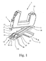
- an electrical or electronic device 1 is shown, which is provided for placement on a rail designed as DIN rail 2.
- the electrical or electronic device 1 itself has a housing 3, which consists of an insulating material, in particular plastic.
- a circuit board 4 is provided in a conventional manner with traces 5 on both sides of the circuit board and not shown electronic components.
- the electrical or electronic device 1 in the rail direction R facing as a knife contacts formed contacts 6a on one side 11a and corresponding, formed as a contact receiving contacts 6b on the other side 11b for a data and / or power bus connection for contacting adjacent, on the mounting rail 2 patch and corresponding contacts having further electronic devices.
- Electrical or electronic devices 1 of the type described above can be strung together on the basis of their training on a mounting rail 2, with a data and / or power bus connection results via the respective contacts 6a, 6b.
- the illustrated electrical or electronic device 1 is also designed in the manner of a stackable terminal and suitable in particular for the Ex-protection area.
- the housing 3 is formed at least in two parts.
- the housing 3 has a circuit board 4 receiving upper part 7 and the contacts 6a, 6b exhibiting base part 8.
- the base part 8 on a circuit board receptacle 9, which projects beyond the top 10 of the base part 8.
- the contacts in the printed circuit board receptacle 9 correspond to the contacts 6a, 6b in the sides 11a, 11b of the base part 8.
- a first latch For releasable connection of the upper part 7 with the base part 8, a first latch is provided, which is designed as a latching connection.
- the latching arm 12, which protrudes downward over the upper part 7, has a latching section 13, which cooperate with two corresponding latching hooks 14, 15 which are provided on the end face 16 of the base part 8.
- the latching hooks 14, 15 and the latching portion 13 each have chamfers in order to facilitate the latching.
- the two latching hooks 14, 15 are spaced apart, so that the latching arm is in the latched state between the latching hooks 14, 15.
- an engagement portion in the form of a pocket 17 is provided at the end of the latching arm 12, in which a tool, such as a screwdriver, used and with the aid of the latching arm 12 can be rebounded.
- the locking connection is provided, located on the other end face on the upper part 7, not shown receiving slot for a corresponding projection 18 on the base part 8, so that the upper part 7 is aufschwenkbar on the base part 8.
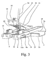
- a second locking is provided for releasable connection of the base part 8 with the support rail 2.
- a not-shown slot for engagement of the corresponding projection 2a of the support rail 2 is provided on the underside 20 of the base part 8.
- a spring-loaded latch 19 Opposite to the pivotal connection is located on the base part 8, a spring-loaded latch 19, which serves for one-sided engagement of the support rail 2 and the corresponding projection 2b of the support rail 2.
- the latch 19 is arranged on the underside 20 of the base part 8.
- the shape of the bolt 19 is approximately U-shaped, wherein the bolt 19 extends over the entire underside 20 of the base part 8.
- the upper ends of the U-legs are angled towards each other and each engage in a corresponding slot 21 on the sides 11a, 11b on the base part 8 a.
- the latch 21 is held captive on Sokkelteil 8.
- On the latch 19 is an actuating opening 22, while in the base part 8 a continuous, accessible from the top 10 forth insertion opening 23 for a tool 24, such as a screwdriver, is provided (see, in particular Fig. 3 and 4 ).
- the insertion opening 23 is only accessible when the upper part 7 has been removed from the base part 8.
- the actuating opening 22 and the insertion opening 23 are offset from one another, wherein insertion of the tool 24 in the operating opening 22 but still possible.
- the actuating opening 22 opens into the insertion opening 23, wherein the latch 19 is moved against the spring load until the locking portion 25 no longer engages the corresponding projection 2b of the support rail 2 and the base part 8 thus of the support rail. 2 can be swung.
- the printed circuit board 4 itself is held in the housing 3 or in the upper part 7 of the housing 3 in a guide, which also facilitates the insertion of the printed circuit board 4 during installation.
- corresponding openings 26 are provided in the circuit board 4 and in the upper part 7, which serve forêten at least one fixing device 27 from the outside of the housing 3 ago.
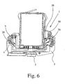
- fixators 27 is of course particularly advantageous in connection with the two-part housings 3 of the type according to the invention, the fixing means 27 may also be provided for fixing the circuit board 4 in a one-piece housing 3, as shown in FIG Fig. 6 is shown.
- the connection of the individual fixing devices 27 to the printed circuit board 4 takes place only via the insertion without a further connection, in particular a soldering is required.
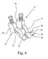
- the fixing device 27 in the in Fig. 5 embodiment illustrated a Einsteckschenkel 28, while in the in the Fig. 6 to 9 illustrated embodiments are each two Einsteckschenkel 28 per fixing device 27 are provided.
- the Einsteckschenkel 28 extend approximately at right angles to the plane of the circuit board 4 and thus coaxial with the DIN rail R. Since the individual Einsteckschenkel 28 are inserted only in the circuit board 4, to improve the connector at least one thickening 29 on Einsteckschenkel 28 is provided.
- a clamping element 30 is provided on the Einsteckschenkel 28 opposite end of the fixing device.
- illustrated terminal element 30 is in this case a screw terminal.
- the openings 27 are each in the range of conductor tracks 5, so that upon insertion of a Einsteckschenkels 28 results in a contact with the relevant interconnect 5.
- the existing in the terminal member 30 contact legs is led out of the terminal member 30 as legs 31. From the leg 31 are bent approximately at right angles to the Einsteckschenkel 28. Before the bending of the Einsteckschenkel 28 is on the leg 31, a step 32 is formed.
- the fixing devices 27 are respectively received in corresponding receptacles 33 in the housing 3 and in the upper part 7 of the housing 3.
- a connection opening is provided for each fixing device 27 and an actuating opening 35 is provided for actuating the clamping element 30.
- a corresponding step-shaped slot 36 is otherwise provided in the receptacle 33, in which the step 32 rests against the housing 3, so that any pressure and tensile loads are transmitted to the housing 3.
- the housing 3 or the upper part 7 has a cover 37 which can be detachably connected to the housing 3 or the upper part 7, in particular latched thereto.
Landscapes
- Engineering & Computer Science (AREA)
- Theoretical Computer Science (AREA)
- Power Engineering (AREA)
- Automation & Control Theory (AREA)
- Physics & Mathematics (AREA)
- General Engineering & Computer Science (AREA)
- General Physics & Mathematics (AREA)
- Human Computer Interaction (AREA)
- Computer Hardware Design (AREA)
- Microelectronics & Electronic Packaging (AREA)
- Mounting Components In General For Electric Apparatus (AREA)
- Developing Agents For Electrophotography (AREA)
- Coupling Device And Connection With Printed Circuit (AREA)
- Photoreceptors In Electrophotography (AREA)
- Lubricants (AREA)
- Mounting Of Printed Circuit Boards And The Like (AREA)
- Telephone Function (AREA)
- Control And Other Processes For Unpacking Of Materials (AREA)
Abstract
Description
Die Erfindung betrifft ein elektrisches oder elektronisches Gerät zum Aufsetzen auf eine Tragschiene, mit einem Gehäuse, mit wenigstens einer im Gehäuse angeordneten Leiterplatte und mit in Längsrichtung der Tragschiene weisenden Kontakten für eine Daten- und/oder Energiebusverbindung mit benachbarten, auf die Tragschiene aufgesetzten und korrespondierende Kontakte aufweisenden Geräten, wobei das Gehäuse mindestens zweiteilig ausgebildet ist und ein die Leiterplatte aufnehmendes Oberteil und ein die Kontakte aufweisendes Sockelteil vorgesehen sind und wobei das Oberteil mit dem Sockelteil über eine erste Verriegelung und das Sockelteil mit der Tragschiene über eine zweite Verriegelung lösbar verbindbar sind.The invention relates to an electrical or electronic device for placement on a mounting rail, comprising a housing, with at least one printed circuit board arranged in the housing and with pointing in the longitudinal direction of the mounting rail contacts for a data and / or power bus connection with adjacent, placed on the mounting rail and corresponding Contacts having devices, wherein the housing is formed at least two parts and a circuit board receiving upper part and the contacts exhibiting base part are provided and wherein the upper part with the base part via a first latch and the base part with the support rail via a second lock are detachably connectable.
Ein elektrisches oder elektronisches Gerät mit einem einteiligen Gehäuse ist aus der
Probleme ergeben sich bei dieser bekannten Konstruktion in dem Fall, wenn die Leiterplatte in dem elektrischen oder elektronischen Gerät defekt ist und das elektrische oder elektronische Gerät zur Reparatur oder Austauschzwecken aus dem Verbund herausgenommen werden muß. Dies führt automatisch zu einer Unterbrechung der Daten- und/oder Energiebusverbindung.Problems arise in this known construction in the case when the printed circuit board in the electrical or electronic device is defective and the electrical or electronic device must be removed from the composite for repair or replacement purposes. This automatically leads to an interruption of the data and / or power bus connection.
Ein elektrisches oder elektronisches Gerät der eingangs genannten Art ist aus der
Aufgabe der vorliegenden Erfindung ist es, ein elektrisches oder elektronisches Gerät der eingangs genannten Art zur Verfügung zu stellen, bei dem ein unbeabsichtigtes Lösen des Sockelteils von der Tragschiene sicher ausgeschlossen werden kann.Object of the present invention is to provide an electrical or electronic device of the type mentioned in which an accidental release of the base part of the mounting rail can be safely excluded.
Die zuvor hergeleitete und aufgezeigte Aufgabe ist erfindungsgemäß durch ein elektrisches oder elektronisches gerät mit den Merkmalen des Anspruchs 1 gelöst. Durch die erfindungsgemäße Ausgestaltung ist nun sichergestellt, daß die zweite Verriegelung keinesfalls vor der ersten Verriegelung gelöst werden kann, da das Oberteil zunächst abgenommen werden muß, um die zweite Verriegelung überhaupt entriegeln zu können. Eine unbeabsichtigte Unterbrechung der Busverbindung ist damit ausgeschlossen.The previously derived and indicated object is achieved by an electrical or electronic device with the features of
Bevorzugt sind die erste und zweite Verriegelung jeweils als Rastverbindung ausgeführt, da sich eine derartige Verriegelung schnell und einfach realisieren läßt. Bei einer vorteilhaften Ausführungsform ist am Oberteil ein federnder Rastarm vorgesehen, während am Sockelteil zum Rastarm korrespondierende Rasthaken vorgesehen sind.Preferably, the first and second locking are each designed as a latching connection, since such locking can be realized quickly and easily. In an advantageous embodiment, a resilient latching arm is provided on the upper part, while on the base part to the latching arm corresponding latching hooks are provided.
Erfindungsgemäß ist weiterhin vorgesehen; daß das Oberteil auf das Sockelteil aufschwenkbar ist, wobei die erste Verriegelung einen von der Außenseite des Gehäuses manuell zu betätigenden Griff- oder Eingriffsabschnitt am Rastarm zum Lösen des Oberteils vom Sockelteil aufweist. Das Lösen des Oberteils vom Sockelteil kann bei dieser Ausführungsform extrem einfach durch Lösen nur einer Rastverbindung realisiert werden. Über den Griff- oder Eingriffsabschnitt kann der Rastarm manuell per Hand oder mit Hilfe eines Werkzeugs, beispielsweise eines Schraubendrehers, geöffnet werden.According to the invention is further provided; in that the upper part can be pivoted onto the base part, wherein the first locking device has a grip or engagement section on the latching arm for releasing the upper part from the base part, which is manually operable from the outside of the housing. The release of the upper part of the base part can be realized in this embodiment extremely simple by releasing only one locking connection. About the handle or engagement portion of the locking arm can be manually opened by hand or with the aid of a tool, such as a screwdriver.
Damit beim Lösen bzw. Entriegeln des Oberteils vom Sockelteil das Sockelteil nicht mit gelöst wird, was im schlimmsten Falle eine Unterbrechung der Daten- und/oder Energiebusverbindung bedeuten würde, ist eine zweite rastbare Verriegelung zur lösbaren Verbindung des Sockelteils mit der Tragschiene vorgesehen. Wichtig ist hierbei, daß die zweite Verriegelung völlig unabhängig von der ersten Verriegelung ist, so daß ein Lösen der ersten Verriegelung nicht unbeabsichtigterweise zu einem Lösen auch der zweiten Verriegelung führen kann.Thus, when releasing or unlocking the upper part of the base part of the base part is not solved, which would mean in the worst case, an interruption of the data and / or power bus connection, a second latchable lock for releasably connecting the base part is provided with the support rail. It is important here that the second lock is completely independent of the first lock, so that a release of the first lock can not unintentionally lead to a release of the second lock.
Um einerseits das Sockelteil in einfacher Weise mit der Tragschiene verbinden zu können und um andererseits ein unbeabsichtigtes Lösen des Sockelteils von der Tragschiene zu verhindern, ist weiterhin vorgesehen, daß das Sockelteil auf die Tragschiene aufschwenkbar ist und die zweite Verriegelung einen federbelasteten Riegel am Sockelteil zum einseitigen Verriegeln der Tragschiene aufweist.On the one hand to be able to connect the base part in a simple manner with the mounting rail and on the other hand to prevent inadvertent release of the base part of the mounting rail, it is further provided that the base part is aufschwenkbar on the mounting rail and the second locking a spring-loaded latch on the base part for one-sided Has locking the mounting rail.
Der Riegel ist dabei im Bereich der Unterseite des Sockelteils angeordnet und damit von außen her an sich nicht zugänglich. Zum Öffnen der zweiten Verriegelung ist am Riegel eine Betätigungsöffnung und auf der Oberseite des Sockelteils eine Einführöffnung für ein Werkzeug, beispielsweise einen Schraubendreher, vorgesehen, wobei die Betätigungsöffnung derart versetzt zur Einführöffnung angeordnet ist, daß beim Einführen des Werkzeugs in die Betätigungs- und Einführöffnung der Riegel entgegen der Federbelastung bewegt und das Sockelteil freigegeben wird. Die Einführöffnung am Sockelteil ist nur bei abgenommenem Oberteil zugänglich ist.The bolt is arranged in the region of the underside of the base part and thus not accessible from the outside per se. To open the second lock is on the latch an actuating opening and on the top of the base part an insertion opening for a tool, such as a screwdriver, provided, wherein the actuating opening is arranged offset from the insertion so that moves when inserting the tool into the actuating and insertion opening of the bolt against the spring load and the base part is released. The insertion opening on the base part is accessible only when the upper part is removed.
Damit die Leiterplatte im Gehäuse richtig angeordnet ist, d. h. in jedem Falle korrekt in einer am Sockelteil vorgegebenen Leiterplattenaufnahme mit den dort vorgesehenen Kontakten kontaktiert und damit außerdem sichergestellt ist, daß die Leiterplatte beim Abnehmen des Oberteils vom Sockelteil mit abgezogen wird, ist erfindungsgemäß außerdem vorgesehen, daß in der Leiterplatte und im Oberteil jeweils korrespondierende Öffnungen zum Einstecken wenigstens einer Fixiereinrichtung von der Außenseite des Gehäuses vorgesehen sind. Zur Erzielung einer guten Verbindung reicht es dabei aus, die Fixiereinrichtung lediglich in die Leiterplatte einzustecken. Die Fixierung erfolgt vorliegend also ausschließlich durch das Einstecken der Fixiereinrichtung von außen her in die Öffnungen im Oberteil und der Leiterplatte. Dieses Einstecken ist nur dann möglich, wenn die jeweiligen Öffnungen im Oberteil und der Leiterplatte ausgefluchtet sind. Bei ausgefluchteten Öffnungen befindet sich die Leiterplatte dann in der gewünschten Einbau- und Kontaktierungsposition.Thus, the circuit board is properly arranged in the housing, d. H. in any case, contacted correctly in a specified on the base part PCB receptacle with the contacts provided there and thus also ensures that the circuit board is removed when removing the upper part of the base part with, is also provided according to the invention that in the circuit board and in the upper part respectively corresponding openings for inserting at least one fixing device are provided from the outside of the housing. To achieve a good connection, it is sufficient to insert the fixing device only in the circuit board. The fixation is in the present case therefore exclusively by the insertion of the fixing device from the outside into the openings in the upper part and the circuit board. This insertion is only possible if the respective openings in the upper part and the circuit board are aligned. At aligned openings, the circuit board is then in the desired mounting and contacting position.
Um eine sichere Verbindung der Leiterplatte zum Gehäuse zu erzielen, weist die Fixiereinrichtung wenigstens einen, vorzugsweise jedoch zwei Einsteckschenkel auf, wobei am Einsteckschenkel wenigstens eine Verdickung vorgesehen ist, über die sich ein guter Reibschluß mit der korrespondierenden Öffnung in der Leiterplatte erzielen läßt.In order to achieve a secure connection of the printed circuit board to the housing, the fixing device has at least one, but preferably two Einsteckschenkel, wherein the Einsteckschenkel at least one thickening is provided, can be achieved via which a good frictional engagement with the corresponding opening in the circuit board.
Neben der Fixierungsfunktion kann die Fixiereinrichtung aber auch einen weiteren Zweck erfüllen, nämlich zum elektrischen Anschluß dienen. Häufig müssen nämlich an der Leiterplatte Zuführungskontakte befestigt werden. Dies kann ohne weiteres bei entsprechender Ausbildung über die Fixiereinrichtung erfolgen. Zu diesem Zweck sollte die Fixiereinrichtung wenigstens ein Klemmenelement in Form einer Anschlußklemme aufweisen. In diesem Falle kontaktiert der Einsteckschenkel mit einer Leiterbahn auf der Leiterplatte. Das elektrische oder elektronische Gerät hat dann auch die Funktion einer anreihbaren Klemme.In addition to the fixation function, however, the fixing device can also fulfill a further purpose, namely to serve for electrical connection. Frequently, namely to be attached to the circuit board supply contacts. This can easily be done with appropriate training on the fixing. For this purpose, the fixing device should have at least one terminal element in the form of a terminal. In this case, the Einsteckschenkel contacted with a conductor on the circuit board. The electrical or electronic device then has the function of a stackable terminal.
Damit die Fixiereinrichtung nicht über das elektrische oder elektronische Gerät seitlich übersteht, ist bei einer vorteilhaften Ausführungsform vorgesehen, daß die Fixiereinrichtung in einer korrespondierenden Aufnahme im Oberteil aufgenommen ist. Wenn bei dieser Ausführungsform die Fixiereinrichtung wenigstens ein Klemmenelement aufweist, also zum Anschluß von Zuführungskontakten dient, ist im Oberteil wenigstens eine Anschlußöffnung zum Einführen des Zuführungskontaktes in das Klemmenelement und wenigstens eine Betätigungsöffnung zur Betätigung des Klemmenelementes vorgesehen.So that the fixing device does not protrude laterally beyond the electrical or electronic device, it is provided in an advantageous embodiment that the fixing device is received in a corresponding receptacle in the upper part. In this embodiment, if the fixing device has at least one clamping element, that is to say for connecting supply contacts, at least one connection opening is provided in the upper part for insertion of the feed contact into the clamping element and at least one actuating opening for actuating the clamping element.
Damit die Fixiereinrichtung während des Gebrauchs des Klemmenelemtens keinen mechanischen Beanspruchungen unterliegt, die sich auf die Leiterplatte übertragen könnten, weist die Fixiereinrichtung einen aus dem Klemmenelement herausragenden Schenkel auf, von dem der Einsteckschenkel absteht. An dem Schenkel ist nun eine Stufe vorgesehen, während sich in der Aufnahme ein korrespondierender stufenförmiger Schlitz befindet, in dem die Stufe des Schenkels am Gehäuse anliegt. Eine etwaige Zug- oder Druckbelastung wird somit vom Gehäuse aufgenommen und nicht auf die Leiterplatte übertragen.So that the fixing device is not subject to any mechanical stresses during use of the clamping element which could be transmitted to the printed circuit board, the fixing device has a leg protruding from the clamping element, from which the plug-in leg protrudes. A step is now provided on the leg, while in the receptacle there is a corresponding step-shaped slot in which the step of the leg bears against the housing. Any tensile or compressive load is thus absorbed by the housing and not transmitted to the circuit board.
Damit die Fixiereinrichtung nicht aus dem elektrischen oder elektronischen Gerät herausfallen kann, ist schließlich eine Abdeckung für die Aufnahme vorgesehen, die lösbar mit dem Gehäuse verbindbar, vorzugsweise verrastbar ist.So that the fixing device can not fall out of the electrical or electronic device, finally, a cover for the receptacle is provided, which is detachably connected to the housing, preferably latched.
Weitere Merkmale, Vorteile und Anwendungsmöglichkeiten der vorliegenden Erfindung ergeben sich aus der nachfolgenden Beschreibung von Ausführungsbeispielen anhand der Zeichnung und der Zeichnung selbst.Further features, advantages and possible applications of the present invention will become apparent from the following description of exemplary embodiments with reference to the drawing and the drawing itself.
Es zeigt
- Fig. 1
- eine perspektivische Ansicht eines auf eine Tragschiene aufgesetzten erfindungsgemäßen elektrischen oder elektronischen Gerätes,
- Fig. 2
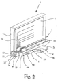
- eine perspektivische Ansicht einer anderen Ausführungsform eines erfindungsgemäßen elektrischen oder elektronischen Gerätes,
- Fig. 3
- eine perspektivische Ansicht von Sockelteilen von erfindungsgemäßen elektrischen oder elektronischen Geräten,
- Fig. 4
- eine andere perspektivische Ansicht von Sockelteilen von erfindungsgemäßen elektrischen oder elektronischen Geräten,
- Fig. 5
- eine Vorderansicht im Schnitt eines Teils eines erfindungsgemäßen elektrischen oder elektronischen Gerätes,
- Fig. 6
- eine Vorderansicht im Schnitt einer anderen Ausführungsform eines erfindungsgemäßen elektrischen oder elektronischen Gerätes,
- Fig. 7
- eine perspektivische Ansicht der Art der Fixierung der Leiterplatte eines erfindungsgemäßen elektrischen oder elektronischen Gerätes unter Weglassung des Gehäuses,
- Fig. 8
- eine perspektivische Ansicht von zwei Fixiereinrichtungen zur Fixierung der Leiterplatte und
- Fig. 9
- eine perspektivische Ansicht eines Teils des Gehäuses eines erfindungsgemäßen elektrischen oder elektronischen Gerätes.
- Fig. 1
- a perspective view of a mounted on a mounting rail electrical or electronic device according to the invention,
- Fig. 2
- a perspective view of another embodiment of an electrical or electronic device according to the invention,
- Fig. 3
- a perspective view of base parts of electrical or electronic devices according to the invention,
- Fig. 4
- another perspective view of base parts of electrical or electronic devices according to the invention,
- Fig. 5
- a front view in section of a part of an electrical or electronic device according to the invention,
- Fig. 6
- a front view in section of another embodiment of an electrical or electronic device according to the invention,
- Fig. 7
- a perspective view of the type of fixing the circuit board of an electrical or electronic device according to the invention omitting the housing,
- Fig. 8
- a perspective view of two fixing devices for fixing the circuit board and
- Fig. 9
- a perspective view of a portion of the housing of an electrical or electronic device according to the invention.
In den Figuren ist ein elektrisches oder elektronisches Gerät 1 dargestellt, das zum Aufsetzen auf eine als Hutschiene ausgebildete Tragschiene 2 vorgesehen ist. Das elektrische oder elektronische Gerät 1 selbst weist ein Gehäuse 3 auf, das aus einem isolierenden Material, insbesondere Kunststoff, besteht. Im Gehäuse 3 befindet sich eine Leiterplatte 4. Die Leiterplatte 4 ist in an sich bekannter Weise mit Leiterbahnen 5 auf beiden Leiterplattenseiten und mit nicht näher dargestellten elektronischen Bauteilen versehen. Des weiteren weist das elektrische oder elektronische Gerät 1 in Tragschienenrichtung R weisende als Messerkontakte ausgebildete Kontakte 6a auf der einen Seite 11a und korrespondierende, als Kontaktaufnahmen ausgebildete Kontakte 6b auf der anderen Seite 11b für eine Daten- und/oder Energiebusverbindung zur Kontaktierung von benachbarten, auf die Tragschiene 2 aufgesetzten und korrespondierende Kontakte aufweisenden weiteren Elektronikgeräten auf. Elektrische oder elektronische Geräte 1 der zuvor beschriebenen Art können aufgrund ihrer Ausbildung auf einer Tragschiene 2 aneinandergereiht werden, wobei sich über die jeweiligen Kontakte 6a, 6b eine Daten- und/oder Energiebusverbindung ergibt. Das dargestellte elektrische oder elektronische Gerät 1 ist außerdem in Art einer anreihbaren Klemme ausgebildet und insbesondere für den Ex-Schutzbereich geeignet.In the figures, an electrical or
Wesentlich ist nun, daß das Gehäuse 3 zumindest zweiteilig ausgebildet ist. Im dargestellten Ausführungsbeispiel weist das Gehäuse 3 ein die Leiterplatte 4 aufnehmendes Oberteil 7 und ein die Kontakte 6a, 6b aufweisendes Sockelteil 8 auf. Zur Kontaktierung mit der Leiterplatte 4 weist das Sockelteil 8 eine Leiterplattenaufnahme 9 auf, die über die Oberseite 10 des Sockelteils 8 übersteht. Die Kontakte in der Leiterplattenaufnahme 9 korrespondieren mit den Kontakten 6a, 6b in den Seiten 11a, 11b des Sockelteils 8.It is essential that the
Zur lösbaren Verbindung des Oberteils 7 mit dem Sockelteil 8 ist eine erste Verriegelung vorgesehen, die als Rastverbindung ausgebildet ist. Hierzu weist die erste Verriegelung einen federnden Rastarm 12 auf, der am Oberteil 7 vorgesehen ist. Der Rastarm 12, der nach unten hin über das Oberteil 7 übersteht, weist einen Rastabschnitt 13 auf, der mit zwei korrespondierenden Rasthaken 14, 15, die an der Stirnseite 16 des Sockelteils 8 vorgesehen sind, zusammenwirken. Die Rasthaken 14, 15 sowie der Rastabschnitt 13 weisen jeweils Auflaufschrägen auf, um das Aufrasten zu erleichtern. Die beiden Rasthaken 14, 15 sind voneinander beabstandet, so daß der Rastarm im verrasteten Zustand zwischen den Rasthaken 14, 15 liegt. Zum Öffnen der Rastverbindung der ersten Verriegelung ist am Ende des Rastarms 12 ein Eingriffsabschnitt in Form einer Tasche 17 vorgesehen, in die ein Werkzeug, wie beispielsweise ein Schraubendreher, eingesetzt und mit dessen Hilfe der Rastarm 12 ausgefedert werden kann. Während an der einen Stirnseite des Gehäuses 3 die Rastverbindung vorgesehen ist, befindet sich an der anderen Stirnseite am Oberteil 7 ein nicht dargestellter Aufnahmeschlitz für einen korrespondierenden Vorsprung 18 am Sockelteil 8, so daß das Oberteil 7 auf das Sockelteil 8 aufschwenkbar ist.For releasable connection of the
Zur lösbaren Verbindung des Sockelteils 8 mit der Tragschiene 2 ist eine zweite Verriegelung vorgesehen. Wie das Oberteil 7 auf das Sockelteil 8 so ist auch das Sockelteil 8 auf die Tragschiene 2 aufschwenkbar. Zu diesem Zweck ist an der Unterseite 20 des Sockelteils 8 ein nicht näher dargestellter Schlitz zum Eingriff des korrespondierenden Vorsprungs 2a der Tragschiene 2 vorgesehen. Gegenüberliegend zu der Schwenkverbindung befindet sich am Sockelteil 8 ein federbelasteter Riegel 19, der zum einseitigen Untergreifen der Tragschiene 2 bzw. des korrespondierenden Vorsprungs 2b der Tragschiene 2 dient.For releasable connection of the
Der Riegel 19 ist an sich an der Unterseite 20 des Sockelteils 8 angeordnet. Die Form des Riegels 19 ist etwa U-förmig, wobei sich der Riegel 19 über die gesamte Unterseite 20 des Sockelteils 8 erstreckt. Die oberen Enden der U-Schenkel sind aufeinander zu abgewinkelt und greifen jeweils in einen korrespondierenden Schlitz 21 an den Seiten 11a, 11b am Sockelteil 8 ein. Hierdurch ist der Riegel 21 unverlierbar am Sokkelteil 8 gehalten. Am Riegel 19 befindet sich eine Betätigungsöffnung 22, während im Sockelteil 8 eine durchgehende, von der Oberseite 10 her zugängliche Einführöffnung 23 für ein Werkzeug 24, wie einen Schraubendreher, vorgesehen ist (vgl. insbesondere
Die Leiterplatte 4 selbst ist im Gehäuse 3 bzw. im Oberteil 7 des Gehäuses 3 in einer Führung gehalten, die auch das Einschieben der Leiterplatte 4 beim Einbau erleichtert. Wie sich insbesondere aus den
Zum Einstecken weist die Fixiereinrichtung 27 bei der in
Neben ihrer Fixierungsfunktion dienen die einzelnen Fixiereinrichtungen 27 vorliegend aber auch zum Anschluß von Zuführungskontakten. Zu diesem Zweck ist am dem Einsteckschenkel 28 gegenüberliegenden Ende der Fixiereinrichtung 27 ein Klemmenelement 30 vorgesehen. Bei dem in den
Der im Klemmenelement 30 vorhandene Kontaktschenkel ist aus dem Klemmenelement 30 als Schenkel 31 herausgeführt. Von dem Schenkel 31 etwa im rechten Winkel abgewinkelt sind die Einsteckschenkel 28. Vor der Abwinkelung der Einsteckschenkel 28 ist am Schenkel 31 eine Stufe 32 ausgebildet.The existing in the
Die Fixiereinrichtungen 27 sind jeweils in korrespondierenden Aufnahmen 33 im Gehäuse 3 bzw. im Oberteil 7 des Gehäuses 3 aufgenommen. Zum Anschluß von Zuführungskontakten ist dabei für jede Fixiereinrichtung 27 eine Anschlußöffnung und zur Betätigung des Klemmelements 30 jeweils eine Betätigungsöffnung 35 vorgesehen. Korrespondierend zur Stufe 32 am Schenkel 31 ist im übrigen in der Aufnahme 33 ein korrespondierender stufenförmiger Schlitz 36 vorgesehen, in dem die Stufe 32 am Gehäuse 3 anliegt, so daß etwaige Druck- und Zugbelastungen auf das Gehäuse 3 übertragen werden.The fixing
Um die Aufnahme 33 verschließen zu können, weist das Gehäuse 3 bzw. das Oberteil 7 eine Abdeckung 37 auf, die lösbar mit dem Gehäuse 3 bzw. dem Oberteil 7 verbunden, insbesondere mit diesem verrastet werden kann.In order to be able to close the
Claims (10)
- Electrical or electronic device (1) for placement on a support rail (2), with a housing (3), with at least one circuit board (4) located in the housing (3), and with contacts (6a, 6b) which point in the lengthwise direction (R) of the support rail for a data and/or power bus connection to adjacent electronic devices have the corresponding contacts and which are placed on the support rail (2),
characterized in
that the housing (3) is formed of at least two parts and a top part (7) housing the circuit board (4) and a base part (8) having contacts (6a, 6b) are provided,
that the top part (7) is detachably attached to the base part (8) using a first locking device and the base part (8) is detachably attached to the support rail (2) using a second locking device
that the second locking device has a spring-loaded latch (19) which is held to slide on the base part (8) for unilateral locking to the support rail (2),
that the latch (19) is located in the area of the bottom (20) of the base part (8),
that on the latch (19) there is an actuation opening (22) and on the top side (10) of the base part (8) there is a continuous insertion opening (23), accessible from the top (10) of the base part (8), for a tool (24), wherein the insertion opening (23) is only accessible when the top part (7) is removed,
so that the second locking device can only be released after releasing the first locking device and removing the top part (7) from the base part (8),
that the actuation opening (22) in the locked state of the base part (8) is arranged offset to the insertion opening (22) such that when the tool (24) is inserted the actuation opening becomes larger, the latch (19) is moved against the spring load and the base part (8) is released, and
that the base part (8) can be swivelled onto the support rail (2). - Electrical or electronic device according to claim 1, characterized in that the first locking device and/or the second locking device is/are formed as catch connections.
- Electrical or electronic device according to claim 2, characterized in that the first locking device has at least one spring-loaded catch arm (12) and catch hooks (14, 15) which correspond to the catch arm (12), and wherein preferably there is a catch arm (12) on the top part (7) and there are catch hooks (14, 15) on the base part (8).
- Electrical or electronic device according to any one of claims 1 to 3, characterized in that the top part (7) can be swivelled onto the base part (8), and wherein preferably the first locking device has a handle or engagement section which can be manually activated from the outside of the housing (3) on the catch arm (12) for detachment of the top part (7) from the base part (8).
- Electrical or electronic device according to any one of claims 1 to 4, characterized in that the circuit board (4) and in the top part (7) there are the corresponding openings (26) for insertion of at least one fixing means (27) from the outside of the housing (3) and wherein preferably the fixing means (27) for connection to the circuit board (4) is simply inserted into the latter without being further connected to the circuit board (4)
- Electrical or electronic device according to claim 5, characterized in that the fixing means (27) has at least one, preferably two insertion legs (28) aligned in the lengthwise direction (R) of the support rail, and wherein preferably on the insertion leg (28) there is at least one thickened area (29).
- Electrical or electronic device according to claim 5 or 6, characterized in that there is a fixing means (27) for electrical connection, wherein preferably the fixing means (27) has at least one terminal element (30), and wherein the insertion leg (28) makes contact with at least one printed conductor (5) of the circuit board (4).
- Electrical or electronic device according to any one of claims 5 to 7, characterized in that the fixing means (27) is held in a corresponding receiver (33) in the top part (7) and wherein preferably in the top part (7) there is at least one connection opening (34) and there is at least one actuation opening (35) for the terminal element (30).
- Electrical or electronic device according to claim 7 or 8, characterized in that the fixing means (27) has a leg (31) which projects out of the terminal element (30) and from which the insertion leg (28) projects, and wherein on the leg (31) there is a step (32) and in the receiver (33) there is a corresponding step-shaped slot (36) in which the step (32) is located and adjoins the housing (3).
- Electrical or electronic device according to claim 8 or 9, characterized in that there is a cover (37) for the receiver (33) and wherein preferably the cover (37) can be detachably joined to the housing (3), especially can catch.
Applications Claiming Priority (3)
| Application Number | Priority Date | Filing Date | Title |
|---|---|---|---|
| DE19710768 | 1997-03-16 | ||
| DE19710768A DE19710768C2 (en) | 1997-03-16 | 1997-03-16 | Electrical or electronic device |
| PCT/EP1998/001396 WO1998042045A1 (en) | 1997-03-16 | 1998-03-11 | Electrical or electronic apparatus |
Publications (3)
| Publication Number | Publication Date |
|---|---|
| EP0920714A1 EP0920714A1 (en) | 1999-06-09 |
| EP0920714B1 EP0920714B1 (en) | 2004-05-06 |
| EP0920714B2 true EP0920714B2 (en) | 2009-11-04 |
Family
ID=7823468
Family Applications (1)
| Application Number | Title | Priority Date | Filing Date |
|---|---|---|---|
| EP98916916A Expired - Lifetime EP0920714B2 (en) | 1997-03-16 | 1998-03-11 | Electrical or electronic apparatus |
Country Status (7)
| Country | Link |
|---|---|
| US (1) | US6172877B1 (en) |
| EP (1) | EP0920714B2 (en) |
| AT (1) | ATE266265T1 (en) |
| DE (3) | DE19710768C2 (en) |
| DK (1) | DK0920714T4 (en) |
| ES (1) | ES2217545T5 (en) |
| WO (1) | WO1998042045A1 (en) |
Families Citing this family (54)
| Publication number | Priority date | Publication date | Assignee | Title |
|---|---|---|---|---|
| ATE236503T1 (en) † | 1997-08-05 | 2003-04-15 | Phoenix Contact Gmbh & Co | ELECTRICAL OR ELECTRONIC DEVICE |
| DE19807710C2 (en) * | 1998-02-24 | 2002-07-18 | Siemens Ag | Modular automation device and assembly of a modular automation device |
| DE19816170C5 (en) * | 1998-04-09 | 2004-09-23 | Sew-Eurodrive Gmbh & Co | control module |
| DE19838493C1 (en) * | 1998-08-25 | 2000-05-11 | Stahl R Schaltgeraete Gmbh | Add-on busbar |
| GB9823160D0 (en) * | 1998-10-22 | 1998-12-16 | Parker Hannifin Plc | A mounting station and drive for mounting thereon |
| DE19964150A1 (en) * | 1999-01-25 | 2000-09-07 | Weidmueller Interface | Encoding device for encoding electrical device has journals and bushes with polygonal or circular shapes aligned according to code system that engage when components are joined |
| DE19902811C1 (en) * | 1999-01-25 | 2000-09-14 | Weidmueller Interface | Coding device for electrical apparatus component e.g. automisation apparatus module disc, has individual coding sections of coding element combined by flexible flat U-shaped grip hoop |
| DE29901194U1 (en) | 1999-01-25 | 1999-05-20 | Weidmüller Interface GmbH & Co., 32760 Detmold | Bus conductor section for an electrical device |
| US6425770B1 (en) * | 2000-04-14 | 2002-07-30 | Rockwell Automation Technologies, Inc. | Input/output device having removable module |
| DE20103978U1 (en) * | 2001-03-07 | 2002-07-11 | Weidmüller Interface GmbH & Co., 32760 Detmold | Electrical device with bus conductor section |
| DE10127997C1 (en) * | 2001-06-08 | 2002-10-10 | Sws Glasbaubeschlaege Gmbh | Holder for electrical and/or electronic switch and/or signal units with plate-shaped bearer is clamping holder with holding slot for bearer, can be combined with supporting foot or wall holder |
| DE20120690U1 (en) * | 2001-12-20 | 2003-02-13 | Weidmüller Interface GmbH & Co., 32760 Detmold | Terminal block with circuit board |
| EP1326304A3 (en) * | 2001-12-20 | 2008-09-24 | Weidmüller Interface GmbH & Co. | Terminal block with circuit board |
| DE10211438A1 (en) * | 2002-03-07 | 2003-10-09 | Koop Peter | Housing system for accommodating slide-in devices |
| DE10351479B4 (en) * | 2002-11-08 | 2012-05-10 | E. Dold & Söhne KG | Device system with electrical equipment mounted on a mounting rail and BUS cable |
| DE102005016760B4 (en) * | 2005-04-11 | 2007-05-31 | Jetter Ag | Arrangement of electrical or electronic devices |
| US7524214B2 (en) * | 2005-12-27 | 2009-04-28 | The Boeing Company | Electrical quick lock interconnect |
| DE202006015897U1 (en) | 2006-10-13 | 2007-03-08 | Phoenix Contact Gmbh & Co. Kg | Electrical or electronic device for attaching to mounting rail, has locking unit provided for locking inserted connector and arranged at housing in area within plug connection in pivotable manner, where locking unit is designed in U-shape |
| DE102006057766B4 (en) * | 2006-12-07 | 2010-02-04 | Siemens Ag | Fastening device of electronic modules on mounting rail |
| DE102007017571B4 (en) | 2007-04-12 | 2009-12-31 | Phoenix Contact Gmbh & Co. Kg | Electric transfer module |
| FR2932316B1 (en) * | 2008-06-09 | 2010-10-29 | Hispano Suiza Sa | MALE-FEMALE CONNECTOR FOR PRINTED CIRCUIT BOARD |
| JP5248398B2 (en) * | 2009-04-07 | 2013-07-31 | 富士通コンポーネント株式会社 | connector |
| IT1398272B1 (en) * | 2009-04-21 | 2013-02-22 | Morsettitalia Spa | ELECTRICAL CONNECTION ELEMENT FOR TERMINALS CONTAINING PRINTED CIRCUITS AND TERMINAL INCLUDING SUCH CONNECTION ELEMENT |
| DE102009059014A1 (en) * | 2009-12-17 | 2011-06-22 | Phoenix Contact GmbH & Co. KG, 32825 | Device for fastening a module unit on a mounting rail |
| DE102009059010A1 (en) * | 2009-12-17 | 2011-06-22 | Phoenix Contact GmbH & Co. KG, 32825 | module unit |
| US8986033B2 (en) * | 2010-03-31 | 2015-03-24 | Weidmueller Interface Gmbh & Co. Kg | Connection module being capable of serving as a bus |
| US8961201B2 (en) | 2010-05-10 | 2015-02-24 | Weidmueller Interface Gmbh & Co. Kg | Mounting rail bus system |
| DE102010016865A1 (en) * | 2010-05-10 | 2011-11-10 | Weidmüller Interface GmbH & Co. KG | Rail bus system |
| DE202010010275U1 (en) * | 2010-07-15 | 2011-12-20 | Weidmüller Interface GmbH & Co. KG | Electrical contact part |
| DE102011110183B3 (en) | 2011-08-09 | 2012-11-15 | Pilz Gmbh & Co. Kg | Modular control device |
| DE102011110184A1 (en) | 2011-08-09 | 2013-02-14 | Pilz Gmbh & Co. Kg | Modular control device |
| DE102011052964B4 (en) | 2011-08-24 | 2019-01-31 | Phoenix Contact Gmbh & Co. Kg | Electrical contact element for cross-routing between I / O modules |
| DE102011081806A1 (en) | 2011-08-30 | 2013-02-28 | Siemens Aktiengesellschaft | Safe motor starter |
| DE202011105337U1 (en) | 2011-09-06 | 2011-11-21 | Systeme Helmholz Gmbh | Device for the electrical and mechanical connection of modules of a modular automation system |
| ITMI20120457A1 (en) | 2012-03-23 | 2013-09-24 | Morsettitalia Spa | HOUSING FOR ELECTRIC / ELECTRONIC CIRCUITS EQUIPPED WITH LOCATIONS AND RELATED CONTACT ELEMENTS FOR ELECTRICAL WIRING CONNECTORS |
| DE102012213258A1 (en) * | 2012-07-27 | 2014-01-30 | Siemens Aktiengesellschaft | connection system |
| DE102012213281B4 (en) * | 2012-07-27 | 2024-06-06 | Phoenix Contact Gmbh & Co. Kg | Fieldbus modular system, carrier module and fieldbus module |
| DE102012110698B3 (en) * | 2012-11-08 | 2014-02-27 | Pilz Gmbh & Co. Kg | Device for controlling and / or regulating a technical installation |
| DE102012023069A1 (en) | 2012-11-26 | 2014-05-28 | Tq-Systems Gmbh | Modular control system |
| US9455510B2 (en) | 2013-01-15 | 2016-09-27 | Weidmueller Interface Gmbh & Co. Kg | Attachment having a module and an electronics atachment |
| DE102013206147B4 (en) * | 2013-04-08 | 2022-06-09 | Beckhoff Automation Gmbh | Dongle module and automation system |
| DE102014103575B4 (en) * | 2014-03-17 | 2024-06-27 | OBO Bettermann Hungary Kft. | Device for protection against overvoltage |
| US9583849B1 (en) * | 2015-09-16 | 2017-02-28 | Dinkle Enterprise Co., Ltd. | Connector module with multiple connection modes |
| DE202016100307U1 (en) * | 2016-01-22 | 2017-04-26 | Weidmüller Interface GmbH & Co. KG | Series device arrangement with a power bus system |
| DE102016004308A1 (en) * | 2016-04-12 | 2017-10-12 | E. Dold & Söhne KG | Electronics assembly Coverset |
| DE202017104591U1 (en) * | 2017-08-01 | 2018-11-06 | Wago Verwaltungsgesellschaft Mbh | Base unit for DIN rail mounted device |
| CN111208875B (en) * | 2018-11-21 | 2023-10-03 | 英业达科技有限公司 | Server device |
| BE1026797B1 (en) | 2018-11-26 | 2020-06-22 | Phoenix Contact Gmbh & Co | Modular switching device for controlling at least one electric drive |
| DE102018133657A1 (en) | 2018-12-28 | 2020-07-02 | Beckhoff Automation Gmbh | BASIC MODULE AND FUNCTIONAL MODULE FOR A CONTROL CABINET SYSTEM AND CONTROL CABINET SYSTEM |
| DE102018133647A1 (en) * | 2018-12-28 | 2020-07-02 | Beckhoff Automation Gmbh | Control cabinet system consisting of basic module and function modules as well as function module |
| DE102018133646A1 (en) | 2018-12-28 | 2020-07-02 | Beckhoff Automation Gmbh | Basic module and function module for a control cabinet system |
| DE102019106082B4 (en) | 2019-03-11 | 2021-06-24 | Beckhoff Automation Gmbh | CABINET SYSTEM WITH SEAL INSERT |
| DE102019126628B4 (en) | 2019-10-02 | 2021-06-10 | Phoenix Contact Gmbh & Co. Kg | Electrical device with a locking device |
| DE202020100240U1 (en) | 2020-01-17 | 2021-04-20 | WAGO Verwaltungsgesellschaft mit beschränkter Haftung | Mounting rail adapter and set of mounting rail adapter and electrical assembly |
Citations (6)
| Publication number | Priority date | Publication date | Assignee | Title |
|---|---|---|---|---|
| US3891295A (en) † | 1971-04-15 | 1975-06-24 | Alsthom Cgee | Fixing device for a support means |
| US4228483A (en) † | 1977-03-14 | 1980-10-14 | La Telemechanique Electrique | Sequential control electrical chain comprising assembled coupling connector modules |
| US4516189A (en) † | 1984-02-29 | 1985-05-07 | Johnson Service Company | Control apparatus having modular construction |
| EP0236711A2 (en) † | 1986-02-06 | 1987-09-16 | Siemens Aktiengesellschaft | Automation apparatus |
| DE3922551A1 (en) † | 1989-07-08 | 1991-01-17 | Geyer Gmbh & Co Christian | Electrical switchgear fixture with spring-biased rotary lever - having right-angled arm under cable clamp, and straight arm urging slider against supporting rail |
| DE4327172A1 (en) † | 1993-08-13 | 1995-02-16 | Weigel Mesgeraete Gmbh | Device for the detachable mounting of at least one electrical component on a profiled rail |
Family Cites Families (11)
| Publication number | Priority date | Publication date | Assignee | Title |
|---|---|---|---|---|
| CH502750A (en) | 1969-06-03 | 1971-01-31 | Siemens Ag Albis | Device for holding circuit boards for telecommunications equipment |
| FR2420273A1 (en) * | 1978-03-17 | 1979-10-12 | Alsthom Cgee | PRINTED CIRCUIT BOARD JUNCTION BLOCK |
| DE3633007A1 (en) | 1985-10-25 | 1987-04-30 | Friedrich Karl Hasenpflug | Device for picking up canine excrement (dog toilet) |
| DE3633785A1 (en) * | 1986-10-03 | 1988-04-07 | Siemens Ag | Automation apparatus |
| EP0364618B1 (en) * | 1988-10-18 | 1993-10-13 | Weidmüller Interface GmbH & Co. | Multiple signal transmission device |
| DE4400484C3 (en) * | 1994-01-11 | 2002-05-29 | Pilz Gmbh & Co | Low voltage switchgear |
| DE4402002B4 (en) * | 1994-01-18 | 2005-10-27 | Wago Verwaltungsgesellschaft Mbh | I / O modules / for a data bus |
| DE4402001B4 (en) | 1994-01-18 | 2007-02-22 | Wago Verwaltungsgesellschaft Mbh | I / O module for a data bus |
| IT1271625B (en) * | 1994-04-27 | 1997-06-04 | Bticino Spa | MODULAR ELECTRICAL EQUIPMENT WITH HOOKING DEVICE ON RAIL |
| DE29606007U1 (en) * | 1996-03-20 | 1996-06-20 | Hartmann & Braun Ag, 60487 Frankfurt | Pluggable module housing with a line-up base for standard rail mounting |
| DE29606759U1 (en) * | 1996-04-13 | 1996-06-27 | Klöckner-Moeller GmbH, 53115 Bonn | Multi-part housing in modular design to accommodate a circuit board |
-
1997
- 1997-03-16 DE DE19710768A patent/DE19710768C2/en not_active Expired - Fee Related
- 1997-08-05 DE DE29713960U patent/DE29713960U1/en not_active Expired - Lifetime
-
1998
- 1998-03-11 WO PCT/EP1998/001396 patent/WO1998042045A1/en active IP Right Grant
- 1998-03-11 AT AT98916916T patent/ATE266265T1/en active
- 1998-03-11 US US09/180,898 patent/US6172877B1/en not_active Expired - Lifetime
- 1998-03-11 DK DK98916916.4T patent/DK0920714T4/en active
- 1998-03-11 ES ES98916916T patent/ES2217545T5/en not_active Expired - Lifetime
- 1998-03-11 DE DE59811322T patent/DE59811322D1/en not_active Expired - Fee Related
- 1998-03-11 EP EP98916916A patent/EP0920714B2/en not_active Expired - Lifetime
Patent Citations (6)
| Publication number | Priority date | Publication date | Assignee | Title |
|---|---|---|---|---|
| US3891295A (en) † | 1971-04-15 | 1975-06-24 | Alsthom Cgee | Fixing device for a support means |
| US4228483A (en) † | 1977-03-14 | 1980-10-14 | La Telemechanique Electrique | Sequential control electrical chain comprising assembled coupling connector modules |
| US4516189A (en) † | 1984-02-29 | 1985-05-07 | Johnson Service Company | Control apparatus having modular construction |
| EP0236711A2 (en) † | 1986-02-06 | 1987-09-16 | Siemens Aktiengesellschaft | Automation apparatus |
| DE3922551A1 (en) † | 1989-07-08 | 1991-01-17 | Geyer Gmbh & Co Christian | Electrical switchgear fixture with spring-biased rotary lever - having right-angled arm under cable clamp, and straight arm urging slider against supporting rail |
| DE4327172A1 (en) † | 1993-08-13 | 1995-02-16 | Weigel Mesgeraete Gmbh | Device for the detachable mounting of at least one electrical component on a profiled rail |
Also Published As
| Publication number | Publication date |
|---|---|
| EP0920714A1 (en) | 1999-06-09 |
| ES2217545T3 (en) | 2004-11-01 |
| DE29713960U1 (en) | 1997-12-04 |
| DK0920714T4 (en) | 2010-03-15 |
| EP0920714B1 (en) | 2004-05-06 |
| DK0920714T3 (en) | 2004-08-30 |
| WO1998042045A1 (en) | 1998-09-24 |
| DE19710768A1 (en) | 1998-09-24 |
| DE19710768C2 (en) | 1999-11-11 |
| ES2217545T5 (en) | 2010-04-06 |
| ATE266265T1 (en) | 2004-05-15 |
| DE59811322D1 (en) | 2004-06-09 |
| US6172877B1 (en) | 2001-01-09 |
Similar Documents
| Publication | Publication Date | Title |
|---|---|---|
| EP0920714B2 (en) | Electrical or electronic apparatus | |
| DE102019127464B3 (en) | Connection device for connecting an electrical line | |
| EP2324533B1 (en) | Electrical connection terminal | |
| EP3320582B1 (en) | Connection terminal | |
| DE102006005260A1 (en) | Electrical connection terminal | |
| DE10045498A1 (en) | Electrical terminal block | |
| EP0896504B1 (en) | Electrical or electronic apparatus | |
| DE202006015897U1 (en) | Electrical or electronic device for attaching to mounting rail, has locking unit provided for locking inserted connector and arranged at housing in area within plug connection in pivotable manner, where locking unit is designed in U-shape | |
| DE102016112831B4 (en) | Connection terminal | |
| DE3821411A1 (en) | SWITCH-PLUG COMBINATION FOR PCB | |
| DE4001104A1 (en) | Plug connector for PCB - is flexible enough to allow interchanging of connection arrangement and connected elements | |
| DE3717806A1 (en) | CONNECTING TERMINAL | |
| DE19724581A1 (en) | Socket for printed circuit boards | |
| EP2982324A1 (en) | Socket module, electrosurgical device and set with a socket module | |
| EP0920788B1 (en) | Electrical or electronic device | |
| DE102016105428B4 (en) | terminal | |
| WO2021004893A1 (en) | Direct plug connector | |
| DE102016105414B3 (en) | terminal | |
| DE8135107U1 (en) | Socket for a miniature relay | |
| LU501848B1 (en) | Connection arrangement | |
| EP2262062B1 (en) | Connector | |
| DE19904763C1 (en) | Locking and pulling mechanism for electronic assemblies | |
| LU93147B1 (en) | terminal | |
| DE102022125266A1 (en) | Connection terminal | |
| DE202022002389U1 (en) | Direct plug-in spring force module |
Legal Events
| Date | Code | Title | Description |
|---|---|---|---|
| PUAI | Public reference made under article 153(3) epc to a published international application that has entered the european phase |
Free format text: ORIGINAL CODE: 0009012 |
|
| 17P | Request for examination filed |
Effective date: 19981028 |
|
| AK | Designated contracting states |
Kind code of ref document: A1 Designated state(s): AT BE CH DE DK ES FR GB IT LI NL SE |
|
| 17Q | First examination report despatched |
Effective date: 20010827 |
|
| RAP1 | Party data changed (applicant data changed or rights of an application transferred) |
Owner name: PHOENIX CONTACT GMBH & CO. KG |
|
| GRAP | Despatch of communication of intention to grant a patent |
Free format text: ORIGINAL CODE: EPIDOSNIGR1 |
|
| GRAS | Grant fee paid |
Free format text: ORIGINAL CODE: EPIDOSNIGR3 |
|
| GRAA | (expected) grant |
Free format text: ORIGINAL CODE: 0009210 |
|
| AK | Designated contracting states |
Kind code of ref document: B1 Designated state(s): AT BE CH DE DK ES FR GB IT LI NL SE |
|
| REG | Reference to a national code |
Ref country code: GB Ref legal event code: FG4D Free format text: NOT ENGLISH |
|
| REG | Reference to a national code |
Ref country code: CH Ref legal event code: EP |
|
| REF | Corresponds to: |
Ref document number: 59811322 Country of ref document: DE Date of ref document: 20040609 Kind code of ref document: P |
|
| REG | Reference to a national code |
Ref country code: CH Ref legal event code: NV Representative=s name: KELLER & PARTNER PATENTANWAELTE AG |
|
| GBT | Gb: translation of ep patent filed (gb section 77(6)(a)/1977) |
Effective date: 20040623 |
|
| REG | Reference to a national code |
Ref country code: SE Ref legal event code: TRGR |
|
| REG | Reference to a national code |
Ref country code: DK Ref legal event code: T3 |
|
| REG | Reference to a national code |
Ref country code: ES Ref legal event code: FG2A Ref document number: 2217545 Country of ref document: ES Kind code of ref document: T3 |
|
| ET | Fr: translation filed | ||
| PLAQ | Examination of admissibility of opposition: information related to despatch of communication + time limit deleted |
Free format text: ORIGINAL CODE: EPIDOSDOPE2 |
|
| PLBQ | Unpublished change to opponent data |
Free format text: ORIGINAL CODE: EPIDOS OPPO |
|
| PLBI | Opposition filed |
Free format text: ORIGINAL CODE: 0009260 |
|
| PLAB | Opposition data, opponent's data or that of the opponent's representative modified |
Free format text: ORIGINAL CODE: 0009299OPPO |
|
| PLAQ | Examination of admissibility of opposition: information related to despatch of communication + time limit deleted |
Free format text: ORIGINAL CODE: EPIDOSDOPE2 |
|
| PLAR | Examination of admissibility of opposition: information related to receipt of reply deleted |
Free format text: ORIGINAL CODE: EPIDOSDOPE4 |
|
| PLBQ | Unpublished change to opponent data |
Free format text: ORIGINAL CODE: EPIDOS OPPO |
|
| PLAX | Notice of opposition and request to file observation + time limit sent |
Free format text: ORIGINAL CODE: EPIDOSNOBS2 |
|
| 26 | Opposition filed |
Opponent name: ROCKWELL AUTOMATION INC. Effective date: 20050207 |
|
| R26 | Opposition filed (corrected) |
Opponent name: ROCKWELL AUTOMATION INC. Effective date: 20050207 |
|
| PLBB | Reply of patent proprietor to notice(s) of opposition received |
Free format text: ORIGINAL CODE: EPIDOSNOBS3 |
|
| NLR1 | Nl: opposition has been filed with the epo |
Opponent name: ROCKWELL AUTOMATION INC. |
|
| PLAS | Information related to reply of patent proprietor to notice(s) of opposition deleted |
Free format text: ORIGINAL CODE: EPIDOSDOBS3 |
|
| PLAX | Notice of opposition and request to file observation + time limit sent |
Free format text: ORIGINAL CODE: EPIDOSNOBS2 |
|
| PLAF | Information modified related to communication of a notice of opposition and request to file observations + time limit |
Free format text: ORIGINAL CODE: EPIDOSCOBS2 |
|
| PG25 | Lapsed in a contracting state [announced via postgrant information from national office to epo] |
Ref country code: DE Free format text: LAPSE BECAUSE OF NON-PAYMENT OF DUE FEES Effective date: 20051001 |
|
| PLBB | Reply of patent proprietor to notice(s) of opposition received |
Free format text: ORIGINAL CODE: EPIDOSNOBS3 |
|
| PLAY | Examination report in opposition despatched + time limit |
Free format text: ORIGINAL CODE: EPIDOSNORE2 |
|
| PLAH | Information related to despatch of examination report in opposition + time limit modified |
Free format text: ORIGINAL CODE: EPIDOSCORE2 |
|
| PLBC | Reply to examination report in opposition received |
Free format text: ORIGINAL CODE: EPIDOSNORE3 |
|
| PUAH | Patent maintained in amended form |
Free format text: ORIGINAL CODE: 0009272 |
|
| STAA | Information on the status of an ep patent application or granted ep patent |
Free format text: STATUS: PATENT MAINTAINED AS AMENDED |
|
| 27A | Patent maintained in amended form |
Effective date: 20091104 |
|
| AK | Designated contracting states |
Kind code of ref document: B2 Designated state(s): AT BE CH DE DK ES FR GB IT LI NL SE |
|
| REG | Reference to a national code |
Ref country code: CH Ref legal event code: AEN Free format text: AUFRECHTERHALTUNG DES PATENTES IN GEAENDERTER FORM |
|
| PLAB | Opposition data, opponent's data or that of the opponent's representative modified |
Free format text: ORIGINAL CODE: 0009299OPPO |
|
| NLR2 | Nl: decision of opposition |
Effective date: 20091104 |
|
| REG | Reference to a national code |
Ref country code: SE Ref legal event code: RPEO |
|
| REG | Reference to a national code |
Ref country code: DK Ref legal event code: T4 |
|
| NLR3 | Nl: receipt of modified translations in the netherlands language after an opposition procedure | ||
| REG | Reference to a national code |
Ref country code: ES Ref legal event code: DC2A Date of ref document: 20100128 Kind code of ref document: T5 |
|
| PGFP | Annual fee paid to national office [announced via postgrant information from national office to epo] |
Ref country code: IT Payment date: 20120326 Year of fee payment: 15 |
|
| PGFP | Annual fee paid to national office [announced via postgrant information from national office to epo] |
Ref country code: GB Payment date: 20130326 Year of fee payment: 16 Ref country code: CH Payment date: 20130326 Year of fee payment: 16 Ref country code: DK Payment date: 20130321 Year of fee payment: 16 Ref country code: SE Payment date: 20130326 Year of fee payment: 16 |
|
| PGFP | Annual fee paid to national office [announced via postgrant information from national office to epo] |
Ref country code: AT Payment date: 20130327 Year of fee payment: 16 |
|
| PGFP | Annual fee paid to national office [announced via postgrant information from national office to epo] |
Ref country code: BE Payment date: 20130321 Year of fee payment: 16 |
|
| PGFP | Annual fee paid to national office [announced via postgrant information from national office to epo] |
Ref country code: FR Payment date: 20130419 Year of fee payment: 16 Ref country code: NL Payment date: 20130321 Year of fee payment: 16 |
|
| PGFP | Annual fee paid to national office [announced via postgrant information from national office to epo] |
Ref country code: ES Payment date: 20140307 Year of fee payment: 17 |
|
| REG | Reference to a national code |
Ref country code: DK Ref legal event code: EBP Effective date: 20140331 |
|
| REG | Reference to a national code |
Ref country code: NL Ref legal event code: V1 Effective date: 20141001 |
|
| REG | Reference to a national code |
Ref country code: CH Ref legal event code: PL |
|
| REG | Reference to a national code |
Ref country code: SE Ref legal event code: EUG |
|
| REG | Reference to a national code |
Ref country code: AT Ref legal event code: MM01 Ref document number: 266265 Country of ref document: AT Kind code of ref document: T Effective date: 20140311 |
|
| GBPC | Gb: european patent ceased through non-payment of renewal fee |
Effective date: 20140311 |
|
| PG25 | Lapsed in a contracting state [announced via postgrant information from national office to epo] |
Ref country code: SE Free format text: LAPSE BECAUSE OF NON-PAYMENT OF DUE FEES Effective date: 20140312 |
|
| REG | Reference to a national code |
Ref country code: FR Ref legal event code: ST Effective date: 20141128 |
|
| PG25 | Lapsed in a contracting state [announced via postgrant information from national office to epo] |
Ref country code: LI Free format text: LAPSE BECAUSE OF NON-PAYMENT OF DUE FEES Effective date: 20140331 Ref country code: GB Free format text: LAPSE BECAUSE OF NON-PAYMENT OF DUE FEES Effective date: 20140311 Ref country code: CH Free format text: LAPSE BECAUSE OF NON-PAYMENT OF DUE FEES Effective date: 20140331 Ref country code: FR Free format text: LAPSE BECAUSE OF NON-PAYMENT OF DUE FEES Effective date: 20140331 |
|
| PG25 | Lapsed in a contracting state [announced via postgrant information from national office to epo] |
Ref country code: AT Free format text: LAPSE BECAUSE OF NON-PAYMENT OF DUE FEES Effective date: 20140311 Ref country code: NL Free format text: LAPSE BECAUSE OF NON-PAYMENT OF DUE FEES Effective date: 20141001 |
|
| PG25 | Lapsed in a contracting state [announced via postgrant information from national office to epo] |
Ref country code: IT Free format text: LAPSE BECAUSE OF NON-PAYMENT OF DUE FEES Effective date: 20140311 |
|
| PG25 | Lapsed in a contracting state [announced via postgrant information from national office to epo] |
Ref country code: DK Free format text: LAPSE BECAUSE OF NON-PAYMENT OF DUE FEES Effective date: 20140331 |
|
| REG | Reference to a national code |
Ref country code: ES Ref legal event code: FD2A Effective date: 20160427 |
|
| PG25 | Lapsed in a contracting state [announced via postgrant information from national office to epo] |
Ref country code: ES Free format text: LAPSE BECAUSE OF NON-PAYMENT OF DUE FEES Effective date: 20150312 |
|
| PG25 | Lapsed in a contracting state [announced via postgrant information from national office to epo] |
Ref country code: BE Free format text: LAPSE BECAUSE OF NON-PAYMENT OF DUE FEES Effective date: 20140331 |