EP3320582B1 - Connection terminal - Google Patents
Connection terminal Download PDFInfo
- Publication number
- EP3320582B1 EP3320582B1 EP16734708.7A EP16734708A EP3320582B1 EP 3320582 B1 EP3320582 B1 EP 3320582B1 EP 16734708 A EP16734708 A EP 16734708A EP 3320582 B1 EP3320582 B1 EP 3320582B1
- Authority
- EP
- European Patent Office
- Prior art keywords
- busbar
- leg
- connection terminal
- current bar
- housing
- Prior art date
- Legal status (The legal status is an assumption and is not a legal conclusion. Google has not performed a legal analysis and makes no representation as to the accuracy of the status listed.)
- Active
Links
- 239000004020 conductor Substances 0.000 claims description 49
- 238000003780 insertion Methods 0.000 claims description 7
- 230000037431 insertion Effects 0.000 claims description 7
- 230000001154 acute effect Effects 0.000 claims description 3
- 241000233805 Phoenix Species 0.000 description 1
- 229910000831 Steel Inorganic materials 0.000 description 1
- 230000015572 biosynthetic process Effects 0.000 description 1
- 230000006835 compression Effects 0.000 description 1
- 238000007906 compression Methods 0.000 description 1
- 230000000284 resting effect Effects 0.000 description 1
- 238000005476 soldering Methods 0.000 description 1
- 239000010959 steel Substances 0.000 description 1
Images


Classifications
-
- H—ELECTRICITY
- H01—ELECTRIC ELEMENTS
- H01R—ELECTRICALLY-CONDUCTIVE CONNECTIONS; STRUCTURAL ASSOCIATIONS OF A PLURALITY OF MUTUALLY-INSULATED ELECTRICAL CONNECTING ELEMENTS; COUPLING DEVICES; CURRENT COLLECTORS
- H01R4/00—Electrically-conductive connections between two or more conductive members in direct contact, i.e. touching one another; Means for effecting or maintaining such contact; Electrically-conductive connections having two or more spaced connecting locations for conductors and using contact members penetrating insulation
- H01R4/28—Clamped connections, spring connections
- H01R4/48—Clamped connections, spring connections utilising a spring, clip, or other resilient member
- H01R4/4809—Clamped connections, spring connections utilising a spring, clip, or other resilient member using a leaf spring to bias the conductor toward the busbar
- H01R4/4828—Spring-activating arrangements mounted on or integrally formed with the spring housing
- H01R4/48365—Spring-activating arrangements mounted on or integrally formed with the spring housing with integral release means
-
- H—ELECTRICITY
- H01—ELECTRIC ELEMENTS
- H01R—ELECTRICALLY-CONDUCTIVE CONNECTIONS; STRUCTURAL ASSOCIATIONS OF A PLURALITY OF MUTUALLY-INSULATED ELECTRICAL CONNECTING ELEMENTS; COUPLING DEVICES; CURRENT COLLECTORS
- H01R9/00—Structural associations of a plurality of mutually-insulated electrical connecting elements, e.g. terminal strips or terminal blocks; Terminals or binding posts mounted upon a base or in a case; Bases therefor
- H01R9/22—Bases, e.g. strip, block, panel
-
- H—ELECTRICITY
- H01—ELECTRIC ELEMENTS
- H01R—ELECTRICALLY-CONDUCTIVE CONNECTIONS; STRUCTURAL ASSOCIATIONS OF A PLURALITY OF MUTUALLY-INSULATED ELECTRICAL CONNECTING ELEMENTS; COUPLING DEVICES; CURRENT COLLECTORS
- H01R25/00—Coupling parts adapted for simultaneous co-operation with two or more identical counterparts, e.g. for distributing energy to two or more circuits
- H01R25/14—Rails or bus-bars constructed so that the counterparts can be connected thereto at any point along their length
-
- H—ELECTRICITY
- H01—ELECTRIC ELEMENTS
- H01R—ELECTRICALLY-CONDUCTIVE CONNECTIONS; STRUCTURAL ASSOCIATIONS OF A PLURALITY OF MUTUALLY-INSULATED ELECTRICAL CONNECTING ELEMENTS; COUPLING DEVICES; CURRENT COLLECTORS
- H01R9/00—Structural associations of a plurality of mutually-insulated electrical connecting elements, e.g. terminal strips or terminal blocks; Terminals or binding posts mounted upon a base or in a case; Bases therefor
- H01R9/22—Bases, e.g. strip, block, panel
- H01R9/24—Terminal blocks
- H01R9/26—Clip-on terminal blocks for side-by-side rail- or strip-mounting
- H01R9/2675—Electrical interconnections between two blocks, e.g. by means of busbars
Definitions
- the invention relates to a connection terminal for connecting an electrical conductor to a busbar.
- Connection terminals are known in a large number of embodiments.
- Connection terminals can be designed, for example, for connecting a conductor to a printed circuit board as a so-called print terminal or - as in the context of the present patent application - for connecting an electrical conductor to a busbar.
- shield clamps have been known for many years, with which the cable shield of a generally multi-core cable can be connected to a busbar.
- Such shield clamps are from the Catalog "Terminal Blocks CLIPLINE 1 2011", pages 546 - 548 from Phoenix Contact GmbH & Co. KG known.
- the known shield clamps have an approximately U-shaped metallic connection body, with slots being formed in the two legs of the connection body with which the shield clamp can be plugged onto a busbar with a predetermined thickness.
- a knurled screw is provided, via which a large, resilient pressure piece can be adjusted in height so that the cable to be connected can be clamped between the pressure piece and the busbar.
- connection terminals are only suitable for connecting the cable shield of a cable to a busbar that is connected to reference potential.
- the busbar is connected to a support rail via support blocks, on which several terminal blocks are then arranged, to which the individual wires of the multi-core cable are connected.
- the DE 201 19 510 U1 discloses a collective terminal for connecting a plurality of electrical conductors to a busbar, the connecting terminal has a plurality of spring elements as conductor connection elements and a group busbar.
- steel retaining springs are provided which clamp the busbar to the busbar.
- a rear catch is provided on the housing of the collective connection, which engages behind the busbar.
- the DE 197 53 076 C1 discloses an electrical connection terminal for arrangement on a printed circuit board, to which at least one electrical conductor can be connected.
- the known connection terminal has a housing in which a conductor connection element and a current bar are arranged.
- a conductor insertion opening and a receptacle for a circuit board are formed in the housing.
- One end of the current bar protrudes from the housing, so that this end, which serves as a contact leg, contacts a contact surface on a printed circuit board which is plugged into the receptacle.
- the connection terminal can be arranged on a circuit board with SMD soldering surfaces without through-holes.
- the present invention is based on the object of specifying a connection terminal for connecting an electrical conductor to a busbar, in which connection to the busbar is as simple as possible.
- a secure electrical connection between the conductor to be connected and the busbar should also be ensured if the busbars have certain tolerances in terms of their thickness.
- connection terminal for connecting an electrical conductor to a busbar with the features of claim 1.
- the connection terminal has a housing in which a conductor connection element and a current bar are arranged.
- a conductor insertion opening for inserting the electrical conductor to be connected and a busbar receptacle for receiving the busbar are formed in the housing.
- a conductor connected by means of the conductor connection element is then connected in an electrically conductive manner via the current bar to the busbar arranged in the busbar receptacle.
- the current bar is slidably mounted in the housing, and that a spring element is arranged in the housing in such a way that the spring element applies a force to the current bar in the direction of the busbar receptacle.
- the spring element ensures that there is always a sufficient and largely constant contact force between the current bar and a busbar inserted in the busbar receptacle, so that good electrical contact between the current bar and the busbar is ensured. Due to the displaceable arrangement of the current bar in the housing in conjunction with the force acting on the current bar through the spring element in the direction of the busbar receptacle, tolerances in the thickness of the busbar used can be reliably compensated for.
- the spring element is designed as an essentially U-shaped or V-shaped leg spring which has two legs.
- the first leg is supported as a kind of contact leg on an abutment in the housing, while the second leg is in contact with the current bar.
- the contact between the second leg of the leg spring and the current bar can be implemented in that the second leg of the leg spring engages with its free end in a corresponding recess in the current bar.
- the second leg is positively connected to the current bar, so that the position of the free end of the second leg relative to the current bar does not change.
- the second leg of the leg spring is simply on the end of the current bar facing away from the busbar receptacle or the end of the current bar presses against the second leg of the leg spring.
- the formation of a recess in the current bar can be dispensed with here.
- the leg spring is clamped with its two legs between the abutment in the housing and the current bar, and the leg spring can also be secured in its position by corresponding ribs or retaining domes in the housing.
- connection element such as screw connections or tension springs
- a leg spring is particularly preferably used as the conductor connection element, which has a contact leg and a clamping leg, the clamping leg together with the current bar forming a spring-loaded clamping point for the stripped conductor to be connected.
- an actuating opening for inserting the tip of a tool for example a screwdriver, can be formed in the housing in addition to the conductor insertion opening.
- an actuation lever is arranged displaceably in the housing.
- the actuating pusher can be moved from a first position in which the clamping leg of the leg spring is not deflected into a second position in which the clamping leg is deflected by the tip of the operating pusher, so that a connected electrical conductor out of the clamping point and thus also can be pulled out of the conductor entry opening.
- connection terminal preferably has a clamping lever which is rotatably mounted in the housing on the side of the busbar receptacle opposite the current bar.
- the clamping lever has at least one clamping nose which protrudes into the busbar receptacle and, in the case of a busbar arranged in the busbar receptacle, rests against the busbar on the side of the busbar facing away from the current bar.
- a busbar arranged in the busbar receptacle is pressed against the current bar by the clamping lever and clamped between the current bar and the clamping lug of the clamping lever, so that the busbar is also held in the busbar receptacle at the same time.
- the clamping lever preferably also has an actuating projection, the free end of which is at a greater distance from the pivot point of the clamping lever than the clamping lug, so that the actuating projection - when the busbar is not inserted - protrudes further into the busbar receptacle than the clamping lug.
- the clamping lever When the connection terminal with the busbar receptacle is plugged onto a busbar or when the busbar is inserted into the busbar receptacle of the connection terminal, the clamping lever is thereby automatically pivoted until the busbar is completely in the busbar receptacle is arranged, and the busbar is clamped between the clamping lug and the current bar, which is pressed against the busbar by the force of the spring element.
- an additional fixation can be provided.
- the fixation is realized according to a preferred embodiment of the invention by a further spring element which has at least one leg and is arranged in the housing such that the free end of the leg protrudes into the busbar receptacle when no busbar is arranged in the busbar receptacle. If a busbar is inserted into the receptacle, the spring element is deflected against its spring force, the free end of the leg of the spring element resting against the busbar at an acute angle. A busbar introduced into the busbar receptacle is thus secured by self-locking against inadvertent removal of the connection terminal from the busbar in the opposite direction to the attachment direction.
- the use of a spring element for fixing the busbar has the advantage that, on the one hand, the spring element does not noticeably hinder the introduction of the busbar into the busbar receptacle, and on the other hand, the fixation is effective after the busbar has been inserted without the user being actuated requirement.
- the further spring element is preferably also designed as a leg spring which has two legs, the second leg, which is not in contact with the busbar, being supported as a bearing leg on an abutment in the housing.
- connection terminal with a further leg spring serving to fix the busbar
- the connection terminal has an unlocking element according to a further advantageous embodiment.
- the unlocking element is movable on the or arranged in the housing so that it can be brought from a basic position into an unlocked position. In the unlocked position, the leg of the spring element that faces the busbar and fixes the busbar in its position is deflected by the unlocking element so that the free end of the leg no longer rests on the side of the busbar.
- the connection terminal can then be lifted off the busbar counter to the plug-on direction or the busbar can be pulled out of the busbar receptacle counter to the plug-in direction.
- the unlocking element - similar to the actuating lever - could be arranged displaceably in the housing.
- the unlocking element is designed as a lever which is pivotably attached to the housing via a hinge, the unlocking element having a gripping surface for actuation with a finger.
- the actuation of the unlocking element can be carried out very easily by a fitter, for example by simply pressing with a finger on the gripping surface of the lever when lifting the connection terminal from the busbar, whereby the lever is pivoted so that the leg of the spring element is deflected and thereby the Lock is released.
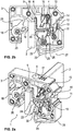
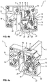
- connection terminal 1 for connecting an electrical conductor - not shown here - to a busbar 2. While in FIG Fig. 1 the connection terminal 1 is shown without busbar 2, show the Fig. 2 , 3 and 4th the connection terminal 1 with two busbars 2 of different thicknesses, namely one with a first, thinner busbar 2 ( Fig. 2 and 4th ) and once with a second, thicker busbar 2 ( Fig. 3 ). In Fig. 4 is the terminal 1 with the thinner busbar 2 according to Fig. 2 shown, whereby in contrast to Fig. 2 the fixing formed between the connection terminal 1 and the busbar 2 is released, so that the connection terminal 1 can be lifted off the busbar 2 in the opposite direction to the attachment direction A.
- the connection terminal 1 has a housing 3 in which a conductor connection element 4 in the form of a leg spring and an L-shaped current bar 5 are arranged. To insert a conductor to be connected into the terminal point, a conductor insertion opening 6 is formed in the housing 3.
- the housing 3, which is usually made of plastic also has a busbar receptacle 7, which is open on one side, so that the connection terminal 1 can be plugged or placed on a busbar 2 with the busbar receptacle 7, which may have already been installed, in the plug-in direction A. If the connection terminal 1 has already been installed, there is the possibility of inserting a busbar 2 into the busbar receptacle 7 from the direction opposite to the direction of attachment A.
- the current bar 5 is mounted in the housing 3 so as to be displaceable - perpendicular to the attachment direction A.
- the current bar 5 is pressed by a spring element 8 with a force in the direction of the busbar receptacle 7 or in the direction of a busbar 2 arranged in the busbar receptacle 7, so that it is ensured that there is always a sufficient contact force and thus a good electrical contact between the current bar 5 and the busbar 2 consists.
- the spring element 8, which presses the current bar 5 against the busbar 2 is designed as a leg spring which has two legs 10, 11.
- the first leg 10 serves as a contact leg which is supported on an abutment 12 in the housing 3, while the second leg 11 is in contact with the current bar 5.
- the second leg 11 rests against the end 13 of the current bar 5 facing away from the busbar receptacle 7.
- the spring element 8 is thus clamped with its two legs 10, 11 between the abutment 12 in the housing 3 and the end 13 of the current bar 5.
- the assembly of the current bar 5 and spring element 8 in the housing 3 is very simple, since the current bar 5 and the spring element 8 can be inserted individually into the housing 3.
- the conductor connection element 4 is also designed as a leg spring which has two legs, namely a contact leg 14 and a clamping leg 15.
- a stripped electrical conductor inserted through the conductor insertion opening 6 into the housing 3 is then through the clamping leg 15 is pressed against the leg 16 of the current bar 5, which is also in contact with an inserted busbar 2.
- the clamping leg 15 thus forms, together with the leg 16 of the current bar 5, a spring force clamping point for the conductor to be connected.
- the connecting terminal 1 has an actuating lever 17 which is arranged displaceably in the housing 3 and which can be displaced from a first position shown in the figures into a second position within the housing 3. While the clamping leg 15 is not deflected in the first position of the actuating printer 17, the clamping leg 15 is deflected in the second position of the actuating lever 17 to such an extent that a connected conductor is no longer clamped in the clamping point and thus out of the connection terminal 1 through the conductor entry opening 6 can be pulled out.
- a clamping lever 18 is rotatably mounted in the housing 3, by means of which the busbar 2 is held in the busbar receptacle 7 and, in particular, is pressed in the direction of the current bar 5.
- the clamping lever 18 thus serves in particular for the correct positioning of the busbar 2 on the current bar 5 or its first leg 16.
- the clamping lever 18 has two clamping lugs 19, 20 protruding into the busbar receptacle 7 and an actuating projection 21.
- the first clamping lug 19 Fig. 2 and 4th
- the second clamping lug 20 Fig. 3
- the free end of the actuating projection 21 is at a greater distance from the pivot point of the clamping lever 18 than the clamping lug 19 and - a significantly greater distance - than the clamping lug 20.
- the actuating projection 21 thus protrudes farthest into the busbar receptacle 7 when the busbar receptacle 7 is free into it, so that when the housing 3 is plugged onto a busbar 2, the busbar 2 first abuts the actuating projection 21 and thereby pivots the clamping lever 18 counterclockwise until the housing 3 is completely placed on the busbar 2, so that according to FIG Fig. 2 the first clamping lug 19 or in the embodiment according to Fig. 3 the second clamping lug 20 rests against the busbar 2 and thereby presses it against the current bar 5.
- a further spring element 22, also designed as a leg spring, is arranged in the housing 3 in addition to the spring element 8 pressing the current bar 5 against a busbar 2.
- a total of three leg springs are thus arranged in the housing 3, all of which perform three different functions.
- the spring element 22 is arranged in the housing 3 below the current bar 5 in such a way that the first leg 23 of the spring element protrudes with its free end 24 into the busbar receptacle 7 if no busbar 2 is arranged there ( Fig. 1 ).
- the leg 23 is deflected against the spring force of the spring element 22, so that the busbar 2 can slide past the free end 24 of the leg 23.
- the free end 24 of the leg 23 rests against the busbar 2 at an acute angle ⁇ .
- the second leg 25 of the spring element 22 in turn serves as a contact leg, for which the leg 25 is supported on a corresponding abutment 26 in the housing 3.
- connection terminal 1 If the connection terminal 1 is to be lifted from a busbar 2 arranged in the busbar receptacle 7 in the opposite direction to the attachment direction A, the leg 23 of the spring element 22 must be deflected counter to the spring force of the spring element 22.
- an unlocking element 27 designed as a lever is provided, which has a flexible Hinge 28 is movably arranged on housing 3.
- the user To actuate the unlocking element 27, the user only has to press one finger on the gripping surface 29, whereby the actuating lug 30 of the unlocking element 27 presses against the leg 23 of the spring element 22 and thereby lifts it off the busbar 2, as shown in FIG Fig. 4 is shown.
- the connection terminal 1 can then easily be lifted off the busbar 2 in the opposite direction to the attachment direction A or the busbar 2 can be pulled - downwards - out of the busbar receptacle 7 in the housing 3.
Description
Die Erfindung betrifft eine Anschlussklemme zum Verbinden eines elektrischen Leiters mit einer Sammelschiene.The invention relates to a connection terminal for connecting an electrical conductor to a busbar.
Elektrische Anschlussklemmen sind in einer Vielzahl von Ausführungsformen bekannt. Anschlussklemmen können beispielsweise zum Anschluss eines Leiters an eine Leiterplatte als sogenannte Printklemme oder - wie im Rahmen der vorliegenden Patentanmeldung - zum Verbinden eines elektrischen Leiters mit einer Sammelschiene ausgebildet sein. Als ein Anwendungsbeispiel derartiger Anschlussklemmen sind seit vielen Jahren Schirmklemmen bekannt, mit denen der Kabelschirm eines in der Regel mehradrigen Kabels an einer Sammelschiene angeschlossen werden kann. Derartige Schirmklemmen sind aus dem
Die bekannten Schirmklemmen weisen einen näherungsweise U-förmigen metallischen Anschlusskörper auf, wobei in den beiden Schenkeln des Anschlusskörpers Schlitze ausgebildet sind, mit denen die Schirmklemme auf eine Sammelschiene mit vorgegebener Dicke aufgesteckt werden kann. Zur Kontaktierung des Kabelschirms eines anzuschließenden Kabels ist eine Rändelschraube vorgesehen, über die ein großflächiges, federndes Druckstück höhenverstellbar ist, so dass das anzuschließende Kabel zwischen dem Druckstück und der Sammelschiene eingeklemmt werden kann.The known shield clamps have an approximately U-shaped metallic connection body, with slots being formed in the two legs of the connection body with which the shield clamp can be plugged onto a busbar with a predetermined thickness. To contact the cable shield of a cable to be connected, a knurled screw is provided, via which a large, resilient pressure piece can be adjusted in height so that the cable to be connected can be clamped between the pressure piece and the busbar.
Die bekannten Anschlussklemmen sind aufgrund ihrer Ausgestaltung und ihres Anschlussprinzips ausschließlich zum Anschließen des Kabelschirms eines Kabels an eine Sammelschiene geeignet, die mit Bezugspotential verbunden ist. In der Regel wird dazu die Sammelschiene über Auflageböcke mit einer Tragschiene verbunden, auf der dann auch mehrere Reihenklemmen angeordnet sind, an die die einzelnen Adern des mehradrigen Kabels angeschlossen werden.Due to their design and their connection principle, the known connection terminals are only suitable for connecting the cable shield of a cable to a busbar that is connected to reference potential. As a rule, the busbar is connected to a support rail via support blocks, on which several terminal blocks are then arranged, to which the individual wires of the multi-core cable are connected.
Die
Die
Der vorliegenden Erfindung liegt die Aufgabe zugrunde, eine Anschlussklemme zum Verbinden eines elektrischen Leiters mit einer Sammelschiene anzugeben, bei der der Anschluss an die Sammelschiene möglichst einfach erfolgt. Dabei soll eine sichere elektrische Verbindung zwischen dem anzuschließenden Leiter und der Sammelschiene auch dann gewährleistet sein, wenn die Sammelschienen in ihrer Dicke gewisse Toleranzen aufweisen.The present invention is based on the object of specifying a connection terminal for connecting an electrical conductor to a busbar, in which connection to the busbar is as simple as possible. A secure electrical connection between the conductor to be connected and the busbar should also be ensured if the busbars have certain tolerances in terms of their thickness.
Diese Aufgabe ist bei einer Anschlussklemme zum Verbinden eines elektrischen Leiters mit einer Sammelschiene mit den Merkmalen des Patentanspruchs 1 gelöst. Die Anschlussklemme weist ein Gehäuse auf, in dem ein Leiteranschlusselement und ein Strombalken angeordnet sind. In dem Gehäuse sind darüber hinaus eine Leitereinführungsöffnung zum Einführen des anzuschließenden elektrischen Leiters und eine Sammelschienenaufnahme zur Aufnahme der Sammelschiene ausgebildet. Ein mittels des Leiteranschlusselements angeschlossener Leiter ist dann über den Strombalken mit der in der Sammelschienenaufnahme angeordneten Sammelschiene elektrisch leitend verbunden.This object is achieved in a connection terminal for connecting an electrical conductor to a busbar with the features of
Bei der Erfindung ist von besonderer Bedeutung, dass der Strombalken verschiebbar im Gehäuse gelagert ist, und dass ein Federelement derart im Gehäuse angeordnet ist, dass das Federelement den Strombalken mit einer Kraft in Richtung der Sammelschienenaufnahme beaufschlagt. Durch das Federelement wird gewährleistet, dass stets eine ausreichende und weitestgehend gleichbleibende Kontaktkraft zwischen dem Strombalken und einer in der Sammelschienenaufnahme eingeführten Sammelschiene besteht, so dass ein guter elektrischer Kontakt zwischen den Strombalken und der Sammelschiene gewährleistet ist. Durch die verschiebbare Anordnung des Strombalkens im Gehäuse im Zusammenspiel mit der durch das Federelement auf den Strombalken wirkenden Kraft in Richtung der Sammelschienenaufnahme können Toleranzen bei der Dicke der verwendeten Sammelschiene zuverlässig ausgeglichen werden.In the invention it is of particular importance that the current bar is slidably mounted in the housing, and that a spring element is arranged in the housing in such a way that the spring element applies a force to the current bar in the direction of the busbar receptacle. The spring element ensures that there is always a sufficient and largely constant contact force between the current bar and a busbar inserted in the busbar receptacle, so that good electrical contact between the current bar and the busbar is ensured. Due to the displaceable arrangement of the current bar in the housing in conjunction with the force acting on the current bar through the spring element in the direction of the busbar receptacle, tolerances in the thickness of the busbar used can be reliably compensated for.
Gemäß einer vorteilhaften Ausgestaltung der erfindungsgemäßen Anschlussklemme ist das Federelement als im wesentlichen U-förmige oder V-förmige Schenkelfeder ausgebildet, die zwei Schenkel aufweist. Der erste Schenkel stützt sich dabei als eine Art Anlageschenkel an einem Widerlager im Gehäuse ab, während der zweite Schenkel mit dem Strombalken in Kontakt ist. Der Kontakt zwischen dem zweiten Schenkel der Schenkelfeder und dem Strombalken kann dabei dadurch realisiert sein, dass der zweite Schenkel der Schenkelfeder mit seinem freien Ende in eine entsprechende Ausnehmung im Strombalken eingreift. Dadurch ist der zweite Schenkel mit dem Strombalken formschlüssig verbunden, so dass sich die Position des freien Endes des zweiten Schenkels zum Strombalken nicht verändert.According to an advantageous embodiment of the connection terminal according to the invention, the spring element is designed as an essentially U-shaped or V-shaped leg spring which has two legs. The first leg is supported as a kind of contact leg on an abutment in the housing, while the second leg is in contact with the current bar. The contact between the second leg of the leg spring and the current bar can be implemented in that the second leg of the leg spring engages with its free end in a corresponding recess in the current bar. As a result, the second leg is positively connected to the current bar, so that the position of the free end of the second leg relative to the current bar does not change.
Gemäß einer bevorzugten, weil konstruktiv besonders einfach zu realisierenden Ausgestaltung der Erfindung liegt der zweite Schenkel der Schenkelfeder einfach an dem der Sammelschienenaufnahme abgewandten Ende des Strombalkens an bzw. das Ende des Strombalkens drückt gegen den zweiten Schenkel der Schenkelfeder. Auf die Ausbildung einer Ausnehmung im Strombalken kann hierbei verzichtet werden. Bei dieser Ausgestaltung ist die Schenkelfeder mit ihren beiden Schenkeln zwischen dem Widerlager im Gehäuse und dem Strombalken eingespannt, wobei die Schenkelfeder zusätzlich durch entsprechende Rippen oder Haltedome im Gehäuse in ihrer Position gesichert sein kann. Ist in die Sammelschienenaufnahme eine Sammelschiene eingesteckt, so wird der Strombalken aus seiner Grundposition etwas in Richtung der Schenkelfeder gedrückt, wodurch die Schenkelfeder etwas entgegen ihrer Federkraft zusammengedrückt wird. Aus der Federkraft der Schenkelfeder resultiert dann die Kraft, mit der der Strombalken gegen die Sammelschiene gedrückt wird, so dass ein guter elektrischer Kontakt zwischen dem Strombalken und der Sammelschiene gewährleistet ist.According to a preferred, because structurally particularly easy to implement embodiment of the invention, the second leg of the leg spring is simply on the end of the current bar facing away from the busbar receptacle or the end of the current bar presses against the second leg of the leg spring. The formation of a recess in the current bar can be dispensed with here. In this embodiment, the leg spring is clamped with its two legs between the abutment in the housing and the current bar, and the leg spring can also be secured in its position by corresponding ribs or retaining domes in the housing. If a busbar is plugged into the busbar receptacle, the current bar is pressed slightly out of its basic position in the direction of the leg spring, as a result of which the leg spring is compressed somewhat against its spring force. The force with which the current bar is pressed against the busbar then results from the spring force of the leg spring, so that good electrical contact between the current bar and the busbar is ensured.
Als Leiteranschlusselement, das im Gehäuse der Anschlussklemme angeordnet ist, kann grundsätzlich nahezu jede bekannte Art von Anschlusselementen, wie beispielsweise Schraubanschlüsse oder Zugfedern verwendet werden. Besonders bevorzugt wird bei der erfindungsgemäßen Anschlussklemme als Leiteranschlusselement jedoch eine Schenkelfeder verwendet, die einen Anlageschenkel und einen Klemmschenkel aufweist, wobei der Klemmschenkel zusammen mit dem Strombalken eine Federkraftklemmstelle für den anzuschließenden, abisolierten Leiter bildet. Mit einer derartigen U-förmigen oder V-förmigen Schenkelfeder kann ein starrer Leiter oder ein mit einer Aderendhülse versehener Leiter direkt, d. h. ohne dass die Klemmstelle vorher mit einem Werkzeug geöffnet werden muss, in die Klemmstelle eingesteckt werden. Die Schenkelfeder wirkt dabei als Druckfeder, die den anzuschließenden Leiter mit dem Klemmschenkel gegen den Strombalken drückt.In principle, almost any known type of connection element, such as screw connections or tension springs, can be used as the conductor connection element which is arranged in the housing of the connection terminal. In the connection terminal according to the invention, however, a leg spring is particularly preferably used as the conductor connection element, which has a contact leg and a clamping leg, the clamping leg together with the current bar forming a spring-loaded clamping point for the stripped conductor to be connected. With such a U-shaped or V-shaped leg spring, a rigid conductor or a conductor provided with a ferrule can be inserted directly into the terminal point, ie without the terminal point having to be opened beforehand with a tool. The leg spring acts as a compression spring which presses the conductor to be connected with the clamping leg against the current bar.
Zum Lösen eines angeschlossenen Leiters aus der Klemmstelle muss der Klemmschenkel der Schenkelfeder ausgelenkt werden, wozu im Gehäuse zusätzlich zur Leitereinführungsöffnung eine Betätigungsöffnung zum Einstecken der Spitze eines Werkzeugs, beispielsweise eines Schraubendrehers, ausgebildet sein kann. Gemäß einer bevorzugten Ausführungsform der erfindungsgemäßen Anschlussklemme ist anstelle einer Betätigungsöffnung für ein Werkzeug ein Betätigungsdrücker verschiebbar im Gehäuse angeordnet. Der Betätigungsdrücker kann dabei aus einer ersten Position, in der der Klemmschenkel der Schenkelfeder nicht ausgelenkt ist, in eine zweite Position verschoben werden, in der der Klemmschenkel durch die Spitze des Betätigungsdrückers ausgelenkt ist, so dass ein angeschlossener elektrischer Leiter aus der Klemmstelle und damit auch aus der Leitereinführungsöffnung herausgezogen werden kann.To release a connected conductor from the clamping point, the clamping leg of the leg spring must be deflected, for which purpose an actuating opening for inserting the tip of a tool, for example a screwdriver, can be formed in the housing in addition to the conductor insertion opening. According to a preferred embodiment of the connection terminal according to the invention, instead of an actuation opening for a tool, an actuation lever is arranged displaceably in the housing. The actuating pusher can be moved from a first position in which the clamping leg of the leg spring is not deflected into a second position in which the clamping leg is deflected by the tip of the operating pusher, so that a connected electrical conductor out of the clamping point and thus also can be pulled out of the conductor entry opening.
Zur Halterung und Positionierung der Sammelschiene in der Sammelschienenaufnahme weist die erfindungsgemäße Anschlussklemme vorzugsweise einen Klemmhebel auf, der auf der dem Strombalken gegenüberliegenden Seite der Sammelschienenaufnahme im Gehäuse drehbar gelagert ist. Der Klemmhebel weist mindestens eine in die Sammelschienenaufnahme hineinragende Klemmnase auf, die bei einer in der Sammelschienenaufnahme angeordneten Sammelschiene an der dem Strombalken abgewandten Seite der Sammelschiene an dieser anliegt. Eine in der Sammelschienenaufnahme angeodnete Sammelschiene wird dabei durch den Klemmhebel gegen den Strombalken gedrückt und zwischen dem Strombalken und der Klemmnase des Klemmhebels eingeklemmt, so dass die Sammelschiene gleichzeitig auch in der Sammelschienenaufnahme gehalten wird.To hold and position the busbar in the busbar receptacle, the connection terminal according to the invention preferably has a clamping lever which is rotatably mounted in the housing on the side of the busbar receptacle opposite the current bar. The clamping lever has at least one clamping nose which protrudes into the busbar receptacle and, in the case of a busbar arranged in the busbar receptacle, rests against the busbar on the side of the busbar facing away from the current bar. A busbar arranged in the busbar receptacle is pressed against the current bar by the clamping lever and clamped between the current bar and the clamping lug of the clamping lever, so that the busbar is also held in the busbar receptacle at the same time.
Zusätzlich zur mindestens einen Klemmnase weist der Klemmhebel vorzugsweise noch einen Betätigungsvorsprung auf, dessen freies Ende einen größeren Abstand vom Drehpunkt des Klemmhebels aufweist als die Klemmnase, so dass der Betätigungsvorsprung - bei nicht eingeführter Sammelschiene - weiter in die Sammelschienenaufnahme hineinragt als die Klemmnase. Beim Aufstecken der Anschlussklemme mit der Sammelschienenaufnahme auf eine Sammelschiene bzw. beim Einstecken der Sammelschiene in die Sammelschienenaufnahme der Anschlussklemme wird dadurch automatisch der Klemmhebel verschwenkt, bis die Sammelschiene vollständig in der Sammelschienenaufnahme angeordnet ist, und die Sammelschiene zwischen der Klemmnase und dem Strombalken, der durch die Kraft des Federelements gegen die Sammelschiene gedrückt wird, eingeklemmt ist.In addition to the at least one clamping lug, the clamping lever preferably also has an actuating projection, the free end of which is at a greater distance from the pivot point of the clamping lever than the clamping lug, so that the actuating projection - when the busbar is not inserted - protrudes further into the busbar receptacle than the clamping lug. When the connection terminal with the busbar receptacle is plugged onto a busbar or when the busbar is inserted into the busbar receptacle of the connection terminal, the clamping lever is thereby automatically pivoted until the busbar is completely in the busbar receptacle is arranged, and the busbar is clamped between the clamping lug and the current bar, which is pressed against the busbar by the force of the spring element.
Um eine sicher Befestigung einer Sammelschiene in der Sammelschienenaufnahme zu gewährleisten und so ein ungewolltes Abziehen einer erfindungsgemäßen Anschlussklemme von der Sammelschiene möglichst zu verhindern, kann eine zusätzliche Fixierung vorgesehen sein. Die Fixierung wird gemäß einer bevorzugten Ausgestaltung der Erfindung durch ein weiteres Federelement realisiert, das mindestens einen Schenkel aufweist und derart im Gehäuse angeordnet ist, dass das freie Ende des Schenkels in die Sammelschienenaufnahme hineinragt, wenn keine Sammelschiene in der Sammelschienenaufnahme angeordnet ist. Wird eine Sammelschiene in die Aufnahme eingeführt, so wird das Federelement gegen seine Federkraft ausgelenkt, wobei das freie Ende des Schenkels des Federelements unter einem spitzen Winkel an der Sammelschiene anliegt. Eine in die Sammelschienenaufnahme eingebrachte Sammelschiene wird somit durch Selbsthemmung gegen ein ungewolltes Abziehen der Anschlussklemme von der Sammelschiene entgegengesetzt zur Aufsteckrichtung gesichert.In order to ensure that a busbar is securely fastened in the busbar receptacle and thus as far as possible to prevent an unintentional pulling off of a connection terminal according to the invention from the busbar, an additional fixation can be provided. The fixation is realized according to a preferred embodiment of the invention by a further spring element which has at least one leg and is arranged in the housing such that the free end of the leg protrudes into the busbar receptacle when no busbar is arranged in the busbar receptacle. If a busbar is inserted into the receptacle, the spring element is deflected against its spring force, the free end of the leg of the spring element resting against the busbar at an acute angle. A busbar introduced into the busbar receptacle is thus secured by self-locking against inadvertent removal of the connection terminal from the busbar in the opposite direction to the attachment direction.
Die Verwendung eines Federelements für die Fixierung der Sammelschiene hat dabei den Vorteil, dass das Federelement zum Einen das Einführen der Sammelschiene in die Sammelschienenaufnahme nicht merklich behindert, zum Anderen die Fixierung nach dem Einführen der Sammelschiene wirksam ist, ohne dass es einer Betätigung durch den Benutzer bedarf. Vorzugsweise ist auch das weitere Federelement als Schenkelfeder ausgebildet, die zwei Schenkel aufweist, wobei sich der zweite Schenkel, der nicht mit der Sammelschiene in Berührung steht, als Anlageschenkel an einem Widerlager im Gehäuse abstützt.The use of a spring element for fixing the busbar has the advantage that, on the one hand, the spring element does not noticeably hinder the introduction of the busbar into the busbar receptacle, and on the other hand, the fixation is effective after the busbar has been inserted without the user being actuated requirement. The further spring element is preferably also designed as a leg spring which has two legs, the second leg, which is not in contact with the busbar, being supported as a bearing leg on an abutment in the housing.
Damit auch bei der bevorzugten Ausgestaltung der Anschlussklemme mit einer weiteren, der Fixierung der Sammelschiene dienenden Schenkelfeder die Anschlussklemme von der Sammelschiene abgehoben bzw. die Sammelschiene aus der Sammelschienenaufnahme herausgezogen werden kann, weist die Anschlussklemme gemäß einer weiteren vorteilhaften Ausgestaltung ein Entriegelungselement auf. Das Entriegelungselement ist dabei beweglich am oder im Gehäuse angeordnet, so dass es aus einer Grundstellung in eine Entriegelungsstellung verbracht werden kann. In der Entriegelungsstellung wird der Schenkel des Federelements, der der Sammelschiene zugewandt ist und die Sammelschiene in ihrer Position fixiert, durch das Entriegelungselement so ausgelenkt, dass das freie Ende des Schenkels nicht mehr an der Seite der Sammelschiene anliegt. Die Anschlussklemme kann dann entgegen der Aufsteckrichtung von der Sammelschiene abgehoben bzw. die Sammelschiene entgegen der Einsteckrichtung aus der Sammelschienenaufnahme herausgezogen werden.So that in the preferred embodiment of the connection terminal with a further leg spring serving to fix the busbar, the connection terminal can be lifted off the busbar or the busbar can be pulled out of the busbar receptacle, the connection terminal has an unlocking element according to a further advantageous embodiment. The unlocking element is movable on the or arranged in the housing so that it can be brought from a basic position into an unlocked position. In the unlocked position, the leg of the spring element that faces the busbar and fixes the busbar in its position is deflected by the unlocking element so that the free end of the leg no longer rests on the side of the busbar. The connection terminal can then be lifted off the busbar counter to the plug-on direction or the busbar can be pulled out of the busbar receptacle counter to the plug-in direction.
Grundsätzlich könnte das Entriegelungselement - ähnlich wie der Betätigungsdrücker - verschiebbar im Gehäuse angeordnet sein. Vorzugsweise ist das Entriegelungselement jedoch als Hebel ausgebildet, der über ein Scharnier am Gehäuse verschwenkbar befestigt ist, wobei das Entriegelungselement eine Grifffläche zur Betätigung mit einem Finger aufweist. Dadurch ist die Betätigung des Entriegelungselements von einem Monteur sehr einfach durchführbar, indem er beispielsweise beim Abheben der Anschlussklemme von der Sammelschiene einfach mit einem Finger auf die Grifffläche des Hebels drückt, wodurch der Hebel verschwenkt wird, so dass der Schenkel des Federelements ausgelenkt und dadurch die Verriegelung gelöst wird.In principle, the unlocking element - similar to the actuating lever - could be arranged displaceably in the housing. Preferably, however, the unlocking element is designed as a lever which is pivotably attached to the housing via a hinge, the unlocking element having a gripping surface for actuation with a finger. As a result, the actuation of the unlocking element can be carried out very easily by a fitter, for example by simply pressing with a finger on the gripping surface of the lever when lifting the connection terminal from the busbar, whereby the lever is pivoted so that the leg of the spring element is deflected and thereby the Lock is released.
Im Einzelnen gibt es nun eine Vielzahl von Möglichkeiten, die erfindungsgemäße Anschlussklemme auszugestalten und weiterzubilden. Dazu wird verwiesen sowohl auf die dem Patentanspruch 1 nachgeordneten Patentansprüche als auch auf die nachfolgende Beschreibung eines bevorzugten Ausführungsbeispiels in Verbindung mit der Zeichnung. In der Zeichnung zeigen
- Fig. 1
- ein Ausführungsbeispiel der Anschlussklemme ohne Sammelschiene, einmal in perspektivischer Darstellung und einmal in Seitenansicht,
- Fig. 2
- die Anschlussklemme gemäß
Fig. 1 , aufgesetzt auf eine erste, schmale Sammelschiene, wiederum in perspektivischer Darstellung und in Seitenansicht, - Fig. 3
- die Anschlussklemme gemäß
Fig. 1 aufgesetzt auf eine zweite, breitere Sammelschiene, wiederum in perspektivischer Darstellung und in Seitenansicht, und - Fig. 4
- die Anschlussklemme gemäß
Fig. 2 , mit betätigtem Entriegelungselement, in perspektivischer Darstellung und in Seitenansicht.
- Fig. 1
- an embodiment of the connection terminal without busbar, once in perspective and once in side view,
- Fig. 2
- the connection terminal according to
Fig. 1 , placed on a first, narrow busbar, again in perspective and in side view, - Fig. 3
- the connection terminal according to
Fig. 1 placed on a second, wider busbar, again in perspective and in side view, and - Fig. 4
- the connection terminal according to
Fig. 2 , with actuated unlocking element, in perspective and in side view.
Die Figuren zeigen ein bevorzugtes Ausführungsbeispiel einer erfindungsgemäßen Anschlussklemme 1 zum Verbinden eines - hier nicht dargestellten - elektrischen Leiters mit einer Sammelschiene 2. Während in
Die erfindungsgemäße Anschlussklemme 1 weist ein Gehäuse 3 auf, in dem ein Leiteranschlusselement 4 in Form einer Schenkelfeder und ein L-förmiger Strombalken 5 angeordnet sind. Zum Einführen eines anzuschließenden Leiters in die Klemmstelle ist in dem Gehäuse 3 eine Leitereinführungsöffnung 6 ausgebildet. Darüber hinaus weist das in der Regel aus Kunststoff bestehende Gehäuse 3 noch eine Sammelschienenaufnahme 7 auf, die einseitig offen ist, so dass die Anschlussklemme 1 auf eine ggf. bereits montierte Sammelschiene 2 mit der Sammelschienenaufnahme 7 in Aufsteckrichtung A aufgesteckt bzw. aufgesetzt werden kann. Ist die Anschlussklemme 1 bereits montiert, so besteht die Möglichkeit, eine Sammelschiene 2 aus der zur Aufsteckrichtung A entgegengesetzten Richtung in die Sammelschienenaufnahme 7 einzustecken.The
Wie aus einem Vergleich der
Bei der Darstellung gemäß
Bei dem in den Figuren dargestellten bevorzugten Ausführungsbeispiel der Anschlussklemme 1 ist das Federelement 8, das den Strombalken 5 gegen die Sammelschiene 2 drückt, als Schenkelfeder ausgebildet, die zwei Schenkel 10, 11 aufweist. Der erste Schenkel 10 dient dabei als Anlageschenkel, der sich an einem Widerlager 12 im Gehäuse 3 abstützt, während der zweite Schenkel 11 mit dem Strombalken 5 in Kontakt steht. Dazu liegt der zweite Schenkel 11 an dem der Sammelschienenaufnahme 7 abgewandten Ende 13 des Strombalkens 5 an. Das Federelement 8 ist somit mit seinen beiden Schenkeln 10, 11 zwischen dem Widerlager 12 im Gehäuse 3 und dem Ende 13 des Strombalkens 5 eingeklemmt. Die Montage von Strombalken 5 und Federelement 8 in das Gehäuse 3 ist dabei sehr einfach, da der Strombalken 5 und das Federelement 8 einzeln in das Gehäuse 3 eingesetzt werden können.In the preferred exemplary embodiment of the
Ebenso wie das Federelement 8 ist bei dem dargestellten Ausführungsbeispiel der Anschlussklemme 1 auch das Leiteranschlusselement 4 als Schenkelfeder ausgebildet, die zwei Schenkel aufweist, nämlich einen Anlageschenkel 14 und einen Klemmschenkel 15. Ein durch die Leitereinführungsöffnung 6 in das Gehäuse 3 eingeführter abisolierter elektrischer Leiter wird dann durch den Klemmschenkel 15 gegen den Schenkel 16 des Strombalkens 5 gedrückt, der auch an einer eingeführten Sammelschiene 2 anliegt. Der Klemmschenkel 15 bildet somit zusammen mit dem Schenkel 16 des Strombalkens 5 eine Federkraftklemmstelle für den anzuschließenden Leiter.Like the
Um einen angeschlossenen Leiter wieder aus der Anschlussklemme 1 herausziehen zu können, muss die Klemmstelle geöffnet werden, wozu der Klemmschenkel 15 ausgelenkt und damit von dem angeschlossenen Leiter abgehoben werden muss. Hierzu weist die Anschlussklemme 1 einen im Gehäuse 3 verschiebbar angeordneten Betätigungsdrücker 17 auf, der aus einer ersten, in den Figuren dargestellten Position, in eine zweite Position innerhalb des Gehäuses 3 verschoben werden kann. Während der Klemmschenkel 15 in der ersten Position des Betätigungsdruckers 17 nicht ausgelenkt ist, ist der Klemmschenkel 15 in der zweiten Position des Betätigungsdrückers 17 soweit ausgelenkt, dass ein angeschlossener Leiter nicht mehr in der Klemmstelle festgeklemmt ist und somit durch die Leitereinführungsöffnung 6 aus der Anschlussklemme 1 herausgezogen werden kann.In order to be able to pull a connected conductor out of the
Auf der dem Strombalken 5 gegenüberliegenden Seite der Sammelschienenaufnahme 7 ist ein Klemmhebel 18 drehbar im Gehäuse 3 gelagert, durch den die Sammelschiene 2 in der Sammelschienenaufnahme 7 gehalten und insbesondere in Richtung des Strombalkens 5 gedrückt wird. Der Klemmhebel 18 dient somit insbesondere zur richtigen Positionierung der Sammelschiene 2 am Strombalken 5 bzw. dessen erstem Schenkel 16. Gemäß der bevorzugten Ausgestaltung weist der Klemmheben 18 zwei in die Sammelschienenaufnahme 7 hineinragende Klemmnasen 19, 20 und einen Betätigungsvorsprung 21 auf. Je nach Dicke der Sammelschiene kontaktiert dabei entweder die erste Klemmnase 19 (
Wie insbesondere aus den
Bei der in den Figuren dargestellten bevorzugten Ausgestaltung der erfindungsgemäßen Anschlussklemme 1 ist neben dem den Strombalken 5 gegen eine Sammelschiene 2 drückenden Federelement 8 noch ein weiteres, ebenfalls als Schenkelfeder ausgebildetes Federelement 22 im Gehäuse 3 angeordnet. Insgesamt sind somit drei Schenkelfedern im Gehäuse 3 angeordnet, die alle drei unterschiedlichen Funktionen wahrnehmen. Das Federelement 22 ist dabei derart im Gehäuse 3 unterhalb des Strombalkens 5 angeordnet, dass der erste Schenkel 23 des Federelements mit seinem freien Ende 24 in die Sammelschienenaufnahme 7 hineinragt, wenn dort keine Sammelschiene 2 angeordnet ist (
Wird das Gehäuse 3 der Anschlussklemme 1 auf eine Sammelschiene 2 aufgesteckt, so wird der Schenkel 23 entgegen der Federkraft des Federelements 22 ausgelenkt, so dass die Sammelschiene 2 an dem freien Ende 24 des Schenkels 23 vorbei gleiten kann. Bei vollständig aufgestecktem Gehäuse 3 liegt das freie Ende 24 des Schenkels 23 unter einem spitzen Winkel α an der Sammelschiene 2 an. Hierdurch wird die Sammelschiene 2 in der Sammelschienenaufnahme 7 durch die Selbsthemmung fixiert und ein ungewolltes Abziehen des Gehäuses 3 von der Sammelschiene 2 bzw. ein ungewolltes Herausziehen der Sammelschiene 2 aus der Sammelschienenaufnahme 7 im Gehäuse 3 verhindert. Der zweite Schenkel 25 des Federelements 22 dient wiederum als Anlageschenkel, wozu sich der Schenkel 25 an einem entsprechenden Widerlager 26 im Gehäuse 3 abstützt.If the
Soll die Anschlussklemme 1 gewollt entgegengesetzt zur Aufsteckrichtung A von einer in der Sammelschienenaufnahme 7 angeordneten Sammelschiene 2 abgehoben werden, so muss der Schenkel 23 des Federelements 22 entgegengesetzt zur Federkraft des Federelements 22 ausgelenkt werden. Hierzu ist ein als Hebel ausgebildetes Entriegelungselement 27 vorgesehen, das über ein flexibles Scharnier 28 am Gehäuse 3 beweglich angeordnet ist. Zur Betätigung des Entriegelungselements 27 muss der Benutzer nur mit einem Finger auf die Grifffläche 29 drücken, wodurch die Betätigungsnase 30 des Entriegelungselements 27 gegen den Schenkel 23 des Federelements 22 drückt und diesen dadurch von der Sammelschiene 2 abhebt, wie dies in
Claims (13)
- Connection terminal (1) for connecting an electrical conductor to a busbar (2), having a housing (3), a conductor connection element (4) and a current bar (5), wherein the housing (3) has a conductor insertion opening (6) for inserting the electrical conductor and a busbar receptacle (7) for receiving the busbar (2), so that a conductor connected by means of the conductor connection element (4) is electrically conductively connected via the current bar (5) to a busbar (2) arranged in the busbar receptacle (7),characterized inthat the current bar (5) is mounted in a manner movable in the direction of the busbar receptacle (7) in the housing (3) andwherein a spring element (8) is arranged in the housing (3) such that the spring element (8) presses on the current bar (5) with a force in the direction of the busbar receptacle (7),so that there is always a sufficient connection force between the current bar (5) and a busbar (2) arranged in the busbar receptacle (7).
- Connection terminal according to claim 1, characterized in that the spring element (8) is designed as a leg spring having two legs (10, 11), wherein the first leg (10) is supported on an abutment (12) in the housing (3) and the second leg (11) is in contact with the current bar (5).
- Connection terminal according to claim 2, characterized in that the second leg (11) of the leg spring engages with its free end in a recess in the current bar (5).
- Connection terminal according to claim 2, characterized in that the second leg (11) of the leg spring rests against the end (13) of the current bar (5) facing away from the busbar receptacle (7).
- Connection terminal according to one of claims 1 to 4, characterized in that the conductor connection element (4) is designed as a leg spring, which has an abutting leg (14) and a clamping leg (15), wherein the clamping leg (15) together with the current bar (5) forms a spring force clamping point for the conductor to be connected.
- Connection terminal according to any one of claims 1 to 5, characterized in that the current bar (5) is L-shaped, wherein a connected conductor rests against one side of the first leg (16) of the current bar (5) and a busbar (2) arranged in the busbar receptacle (7) rests against the opposite side of the first leg (16) of the current bar (5).
- Connection terminal according to claim 5 or 6, characterized in that a push actuator (17) is arranged in a movable manner in the housing (3), which can be moved from a first position, in which the clamping leg (15) is not deflected, into a second position, in which the clamping leg (15) is deflected, so that a connected electrical conductor can be removed from the conductor insertion opening (6).
- Connection terminal according to one of claims 1 to 7, characterized in that a clamping lever (18) is rotatably mounted in the housing (3) on the side of the busbar receptacle (7) opposite the current bar (5), wherein the clamping lever (18) has at least a clamping lug (19, 20) projecting into the busbar receptacle (7), which rests against the side of the busbar (2) facing away from the current bar (5) in the case of a busbar (2) arranged in the busbar receptacle (7).
- Connection terminal according to claim 8, characterized in that the clamping lever (18) has an actuating projection (21) whose free end has a greater distance from the pivot point of the clamping lever (18) than the clamping lug (19, 20), wherein the actuating projection (21) protrudes into the busbar receptacle (7) when no busbar (2) is arranged in the busbar receptacle (7).
- Connection terminal according to any one of claims 1 to 9, characterized in that a further spring element (22) having at least one leg (23) is arranged in the housing (3) such that the free end (24) of the leg (23) protrudes into the busbar receptacle (7) when no busbar (2) is arranged in the busbar receptacle (7), while the spring element (8) is deflected against its spring force when a busbar (2) is arranged in the busbar receptacle (7), wherein the free end (24) of the leg (23) then rests against the busbar (2) at an acute angle α.
- Connection terminal according to claim 10, characterized in that the further spring element (22) is also designed as a leg spring and has a second leg (25) which is supported on an abutment (26) in the housing (3).
- Connection terminal (1) according to claim 10 or 11, characterized in that an unlocking element (27) is arranged in a movable manner on or in the housing (3), which can be moved from a basic position into an unlocking position, wherein the leg (23) of the spring element (22) is deflected by the unlocking element (27) in the unlocked position so that the free end (24) of the leg (23) no longer rests against the side of the busbar (2), so that the connection terminal (1) can be lifted from the busbar (2) against the mounting direction (A).
- Connection terminal according to claim 12, characterized in that the unlocking element (27) is designed as a lever which is fastened to the housing (3) via a hinge (28), wherein the unlocking element (27) preferably has a gripping surface (29) for actuation with a finger.
Applications Claiming Priority (2)
| Application Number | Priority Date | Filing Date | Title |
|---|---|---|---|
| DE102015110868.2A DE102015110868A1 (en) | 2015-07-06 | 2015-07-06 | terminal |
| PCT/EP2016/065967 WO2017005788A1 (en) | 2015-07-06 | 2016-07-06 | Connection terminal |
Publications (2)
| Publication Number | Publication Date |
|---|---|
| EP3320582A1 EP3320582A1 (en) | 2018-05-16 |
| EP3320582B1 true EP3320582B1 (en) | 2022-01-05 |
Family
ID=56345157
Family Applications (1)
| Application Number | Title | Priority Date | Filing Date |
|---|---|---|---|
| EP16734708.7A Active EP3320582B1 (en) | 2015-07-06 | 2016-07-06 | Connection terminal |
Country Status (5)
| Country | Link |
|---|---|
| EP (1) | EP3320582B1 (en) |
| CN (1) | CN107912073B (en) |
| DE (1) | DE102015110868A1 (en) |
| ES (1) | ES2905871T3 (en) |
| WO (1) | WO2017005788A1 (en) |
Families Citing this family (11)
| Publication number | Priority date | Publication date | Assignee | Title |
|---|---|---|---|---|
| DE102016105428B4 (en) * | 2016-03-23 | 2017-10-05 | Phoenix Contact Gmbh & Co. Kg | terminal |
| DE102016105414B3 (en) * | 2016-03-23 | 2017-09-28 | Phoenix Contact Gmbh & Co. Kg | terminal |
| DE102016112831B4 (en) | 2016-07-13 | 2021-12-09 | Phoenix Contact Gmbh & Co. Kg | Connection terminal |
| DE102016120258A1 (en) * | 2016-10-24 | 2018-04-26 | Wieland Electric Gmbh | Electrical terminal block |
| DE102018124622B3 (en) * | 2018-10-05 | 2020-03-12 | Wago Verwaltungsgesellschaft Mbh | Contact insert, arrangement thus formed, conductor connection terminal and method for providing the contact insert |
| BE1026735B1 (en) * | 2018-10-30 | 2020-06-02 | Phoenix Contact Gmbh & Co | Electrical terminal block |
| DE102019126155A1 (en) * | 2019-09-27 | 2021-04-01 | Phoenix Contact Gmbh & Co. Kg | Busbar module and corresponding connection module |
| LU101419B1 (en) | 2019-09-27 | 2021-03-31 | Phoenix Contact Gmbh & Co | Lockable connection module |
| DE102019133530A1 (en) * | 2019-12-09 | 2021-06-10 | Phoenix Contact Gmbh & Co. Kg | Connection device for a shield conductor of an electrical line |
| TW202230893A (en) | 2021-01-01 | 2022-08-01 | 徐宏昇 | Terminal box |
| TW202230890A (en) | 2021-01-01 | 2022-08-01 | 徐宏昇 | Terminal box |
Citations (4)
| Publication number | Priority date | Publication date | Assignee | Title |
|---|---|---|---|---|
| JPH10302855A (en) * | 1997-04-30 | 1998-11-13 | Matsushita Electric Works Ltd | Terminal device |
| EP1898436A2 (en) * | 2006-09-09 | 2008-03-12 | Moeller GmbH | Connector device for connecting to an electric switching device |
| WO2008037229A1 (en) * | 2006-09-25 | 2008-04-03 | Siemens Aktiengesellschaft | Busbar contact-making with bar thickness compenstaion |
| DE102011053082A1 (en) * | 2011-08-29 | 2013-02-28 | Rittal Gmbh & Co. Kg | Busbar contact with rail thickness compensation |
Family Cites Families (16)
| Publication number | Priority date | Publication date | Assignee | Title |
|---|---|---|---|---|
| DE3510210A1 (en) * | 1985-03-21 | 1986-10-02 | Alfred Wöhner GmbH, 8633 Rödental | Connecting terminal for placing on busbars |
| DE8801623U1 (en) * | 1988-02-09 | 1988-04-07 | Broekelmann, Jaeger & Busse Gmbh & Co, 5760 Arnsberg, De | |
| DE3940153C1 (en) * | 1989-12-05 | 1991-01-31 | Rittal-Werk Rudolf Loh Gmbh & Co Kg, 6348 Herborn, De | Installation appts. for bus=bar system - has locking slide with recess for tensioning piece and adjustable vertically w.r.t. bus=bar |
| DE29605365U1 (en) * | 1996-03-22 | 1996-05-30 | Conrad Gerd | Disconnect terminal, especially for neutral |
| DE19714633C1 (en) * | 1997-04-09 | 1998-07-16 | Weidmueller Interface | Terminal-block with bus=bar connector |
| DE59711449D1 (en) * | 1997-08-14 | 2004-04-29 | Phoenix Contact Gmbh & Co | Electrical spring clamp |
| DE19753076C1 (en) * | 1997-11-29 | 1999-08-19 | Lumberg Karl Gmbh & Co | Electrical connector, esp. series connector |
| DE29806196U1 (en) * | 1998-04-03 | 1998-06-18 | Woehner Gmbh & Co Kg | Busbar adapter, especially for fuse switch disconnectors |
| DE29806302U1 (en) * | 1998-04-06 | 1998-06-25 | Woehner Gmbh & Co Kg | Contact device |
| DE19836383C1 (en) * | 1998-08-11 | 2000-01-13 | Woehner Gmbh & Co Kg | Contact device for bus rail adapter can be adjusted for different bus rail thicknesses |
| CN2435856Y (en) * | 2000-07-24 | 2001-06-20 | 江门市江海区汇聪电器厂 | Threadless terminal |
| DE20119510U1 (en) * | 2001-12-03 | 2002-04-18 | Wago Verwaltungs Gmbh | Common connection for electr. distribution systems |
| DE20120811U1 (en) * | 2001-12-21 | 2003-04-30 | Weidmueller Interface | Busbar terminal |
| JP2004165045A (en) * | 2002-11-14 | 2004-06-10 | Nitto Electric Works Ltd | Terminal stand |
| DE102010010262B9 (en) * | 2010-03-03 | 2014-10-23 | Wago Verwaltungsgesellschaft Mbh | Connectors |
| DE102011055919B4 (en) * | 2011-12-01 | 2014-05-15 | Phoenix Contact Gmbh & Co. Kg | terminal |
-
2015
- 2015-07-06 DE DE102015110868.2A patent/DE102015110868A1/en not_active Ceased
-
2016
- 2016-07-06 EP EP16734708.7A patent/EP3320582B1/en active Active
- 2016-07-06 WO PCT/EP2016/065967 patent/WO2017005788A1/en active Application Filing
- 2016-07-06 ES ES16734708T patent/ES2905871T3/en active Active
- 2016-07-06 CN CN201680040021.3A patent/CN107912073B/en active Active
Patent Citations (4)
| Publication number | Priority date | Publication date | Assignee | Title |
|---|---|---|---|---|
| JPH10302855A (en) * | 1997-04-30 | 1998-11-13 | Matsushita Electric Works Ltd | Terminal device |
| EP1898436A2 (en) * | 2006-09-09 | 2008-03-12 | Moeller GmbH | Connector device for connecting to an electric switching device |
| WO2008037229A1 (en) * | 2006-09-25 | 2008-04-03 | Siemens Aktiengesellschaft | Busbar contact-making with bar thickness compenstaion |
| DE102011053082A1 (en) * | 2011-08-29 | 2013-02-28 | Rittal Gmbh & Co. Kg | Busbar contact with rail thickness compensation |
Also Published As
| Publication number | Publication date |
|---|---|
| CN107912073B (en) | 2020-03-24 |
| WO2017005788A1 (en) | 2017-01-12 |
| EP3320582A1 (en) | 2018-05-16 |
| CN107912073A (en) | 2018-04-13 |
| ES2905871T3 (en) | 2022-04-12 |
| DE102015110868A1 (en) | 2017-01-12 |
Similar Documents
| Publication | Publication Date | Title |
|---|---|---|
| EP3320582B1 (en) | Connection terminal | |
| EP2324533B1 (en) | Electrical connection terminal | |
| EP1943702B1 (en) | Terminal block | |
| EP3235061B1 (en) | Electric connection terminal | |
| EP2522052B1 (en) | Spring terminal, in particular a front terminal | |
| WO2010022955A1 (en) | Electrical terminal | |
| DE202010008028U1 (en) | Connection device for conductors | |
| DE202007001701U1 (en) | Universal Contact | |
| DE102006005260A1 (en) | Electrical connection terminal | |
| EP3375046B1 (en) | Electric connection terminal | |
| EP3320583B1 (en) | Connection terminal | |
| DE102017111733A1 (en) | Spring terminal for conductor | |
| DE19835459C2 (en) | Terminal for electrical conductors | |
| EP2917970A1 (en) | Spring force terminal with an actuation means | |
| DE102019111453A1 (en) | Spring clamp terminal for conductors | |
| DE102016112831B4 (en) | Connection terminal | |
| DE102016114289A1 (en) | Electrical connection terminal | |
| DE102008033325A1 (en) | Electrical connecting terminal e.g. tension spring clamp, for connecting electrical cable, has housing provided with cable entry opening, and clamping spring swiveled from position to other position during shifting of actuating slide | |
| DE102010033112B4 (en) | Electrical installation device | |
| EP3685473A1 (en) | Connection device for connecting an electrical cable | |
| DE102019111159B4 (en) | Connection arrangement and connection terminal | |
| DE102016105414B3 (en) | terminal | |
| EP3714511B1 (en) | Connection device for connecting an electrical line | |
| DE102016105428B4 (en) | terminal | |
| DE202008016856U1 (en) | Electrical connection or connection terminal |
Legal Events
| Date | Code | Title | Description |
|---|---|---|---|
| STAA | Information on the status of an ep patent application or granted ep patent |
Free format text: STATUS: THE INTERNATIONAL PUBLICATION HAS BEEN MADE |
|
| PUAI | Public reference made under article 153(3) epc to a published international application that has entered the european phase |
Free format text: ORIGINAL CODE: 0009012 |
|
| STAA | Information on the status of an ep patent application or granted ep patent |
Free format text: STATUS: REQUEST FOR EXAMINATION WAS MADE |
|
| 17P | Request for examination filed |
Effective date: 20180125 |
|
| AK | Designated contracting states |
Kind code of ref document: A1 Designated state(s): AL AT BE BG CH CY CZ DE DK EE ES FI FR GB GR HR HU IE IS IT LI LT LU LV MC MK MT NL NO PL PT RO RS SE SI SK SM TR |
|
| AX | Request for extension of the european patent |
Extension state: BA ME |
|
| DAV | Request for validation of the european patent (deleted) | ||
| DAX | Request for extension of the european patent (deleted) | ||
| STAA | Information on the status of an ep patent application or granted ep patent |
Free format text: STATUS: EXAMINATION IS IN PROGRESS |
|
| 17Q | First examination report despatched |
Effective date: 20200212 |
|
| STAA | Information on the status of an ep patent application or granted ep patent |
Free format text: STATUS: EXAMINATION IS IN PROGRESS |
|
| GRAP | Despatch of communication of intention to grant a patent |
Free format text: ORIGINAL CODE: EPIDOSNIGR1 |
|
| STAA | Information on the status of an ep patent application or granted ep patent |
Free format text: STATUS: GRANT OF PATENT IS INTENDED |
|
| GRAJ | Information related to disapproval of communication of intention to grant by the applicant or resumption of examination proceedings by the epo deleted |
Free format text: ORIGINAL CODE: EPIDOSDIGR1 |
|
| GRAP | Despatch of communication of intention to grant a patent |
Free format text: ORIGINAL CODE: EPIDOSNIGR1 |
|
| INTG | Intention to grant announced |
Effective date: 20210702 |
|
| INTG | Intention to grant announced |
Effective date: 20210720 |
|
| GRAS | Grant fee paid |
Free format text: ORIGINAL CODE: EPIDOSNIGR3 |
|
| GRAA | (expected) grant |
Free format text: ORIGINAL CODE: 0009210 |
|
| STAA | Information on the status of an ep patent application or granted ep patent |
Free format text: STATUS: THE PATENT HAS BEEN GRANTED |
|
| AK | Designated contracting states |
Kind code of ref document: B1 Designated state(s): AL AT BE BG CH CY CZ DE DK EE ES FI FR GB GR HR HU IE IS IT LI LT LU LV MC MK MT NL NO PL PT RO RS SE SI SK SM TR |
|
| REG | Reference to a national code |
Ref country code: GB Ref legal event code: FG4D Free format text: NOT ENGLISH |
|
| REG | Reference to a national code |
Ref country code: CH Ref legal event code: EP |
|
| REG | Reference to a national code |
Ref country code: AT Ref legal event code: REF Ref document number: 1461409 Country of ref document: AT Kind code of ref document: T Effective date: 20220115 |
|
| REG | Reference to a national code |
Ref country code: DE Ref legal event code: R096 Ref document number: 502016014357 Country of ref document: DE |
|
| REG | Reference to a national code |
Ref country code: IE Ref legal event code: FG4D Free format text: LANGUAGE OF EP DOCUMENT: GERMAN |
|
| REG | Reference to a national code |
Ref country code: ES Ref legal event code: FG2A Ref document number: 2905871 Country of ref document: ES Kind code of ref document: T3 Effective date: 20220412 |
|
| REG | Reference to a national code |
Ref country code: LT Ref legal event code: MG9D |
|
| REG | Reference to a national code |
Ref country code: NL Ref legal event code: MP Effective date: 20220105 |
|
| PG25 | Lapsed in a contracting state [announced via postgrant information from national office to epo] |
Ref country code: NL Free format text: LAPSE BECAUSE OF FAILURE TO SUBMIT A TRANSLATION OF THE DESCRIPTION OR TO PAY THE FEE WITHIN THE PRESCRIBED TIME-LIMIT Effective date: 20220105 |
|
| PG25 | Lapsed in a contracting state [announced via postgrant information from national office to epo] |
Ref country code: SE Free format text: LAPSE BECAUSE OF FAILURE TO SUBMIT A TRANSLATION OF THE DESCRIPTION OR TO PAY THE FEE WITHIN THE PRESCRIBED TIME-LIMIT Effective date: 20220105 Ref country code: RS Free format text: LAPSE BECAUSE OF FAILURE TO SUBMIT A TRANSLATION OF THE DESCRIPTION OR TO PAY THE FEE WITHIN THE PRESCRIBED TIME-LIMIT Effective date: 20220105 Ref country code: PT Free format text: LAPSE BECAUSE OF FAILURE TO SUBMIT A TRANSLATION OF THE DESCRIPTION OR TO PAY THE FEE WITHIN THE PRESCRIBED TIME-LIMIT Effective date: 20220505 Ref country code: NO Free format text: LAPSE BECAUSE OF FAILURE TO SUBMIT A TRANSLATION OF THE DESCRIPTION OR TO PAY THE FEE WITHIN THE PRESCRIBED TIME-LIMIT Effective date: 20220405 Ref country code: LT Free format text: LAPSE BECAUSE OF FAILURE TO SUBMIT A TRANSLATION OF THE DESCRIPTION OR TO PAY THE FEE WITHIN THE PRESCRIBED TIME-LIMIT Effective date: 20220105 Ref country code: HR Free format text: LAPSE BECAUSE OF FAILURE TO SUBMIT A TRANSLATION OF THE DESCRIPTION OR TO PAY THE FEE WITHIN THE PRESCRIBED TIME-LIMIT Effective date: 20220105 Ref country code: BG Free format text: LAPSE BECAUSE OF FAILURE TO SUBMIT A TRANSLATION OF THE DESCRIPTION OR TO PAY THE FEE WITHIN THE PRESCRIBED TIME-LIMIT Effective date: 20220405 |
|
| PG25 | Lapsed in a contracting state [announced via postgrant information from national office to epo] |
Ref country code: PL Free format text: LAPSE BECAUSE OF FAILURE TO SUBMIT A TRANSLATION OF THE DESCRIPTION OR TO PAY THE FEE WITHIN THE PRESCRIBED TIME-LIMIT Effective date: 20220105 Ref country code: LV Free format text: LAPSE BECAUSE OF FAILURE TO SUBMIT A TRANSLATION OF THE DESCRIPTION OR TO PAY THE FEE WITHIN THE PRESCRIBED TIME-LIMIT Effective date: 20220105 Ref country code: GR Free format text: LAPSE BECAUSE OF FAILURE TO SUBMIT A TRANSLATION OF THE DESCRIPTION OR TO PAY THE FEE WITHIN THE PRESCRIBED TIME-LIMIT Effective date: 20220406 Ref country code: FI Free format text: LAPSE BECAUSE OF FAILURE TO SUBMIT A TRANSLATION OF THE DESCRIPTION OR TO PAY THE FEE WITHIN THE PRESCRIBED TIME-LIMIT Effective date: 20220105 |
|
| PG25 | Lapsed in a contracting state [announced via postgrant information from national office to epo] |
Ref country code: IS Free format text: LAPSE BECAUSE OF FAILURE TO SUBMIT A TRANSLATION OF THE DESCRIPTION OR TO PAY THE FEE WITHIN THE PRESCRIBED TIME-LIMIT Effective date: 20220505 |
|
| REG | Reference to a national code |
Ref country code: DE Ref legal event code: R097 Ref document number: 502016014357 Country of ref document: DE |
|
| PG25 | Lapsed in a contracting state [announced via postgrant information from national office to epo] |
Ref country code: SM Free format text: LAPSE BECAUSE OF FAILURE TO SUBMIT A TRANSLATION OF THE DESCRIPTION OR TO PAY THE FEE WITHIN THE PRESCRIBED TIME-LIMIT Effective date: 20220105 Ref country code: SK Free format text: LAPSE BECAUSE OF FAILURE TO SUBMIT A TRANSLATION OF THE DESCRIPTION OR TO PAY THE FEE WITHIN THE PRESCRIBED TIME-LIMIT Effective date: 20220105 Ref country code: RO Free format text: LAPSE BECAUSE OF FAILURE TO SUBMIT A TRANSLATION OF THE DESCRIPTION OR TO PAY THE FEE WITHIN THE PRESCRIBED TIME-LIMIT Effective date: 20220105 Ref country code: EE Free format text: LAPSE BECAUSE OF FAILURE TO SUBMIT A TRANSLATION OF THE DESCRIPTION OR TO PAY THE FEE WITHIN THE PRESCRIBED TIME-LIMIT Effective date: 20220105 Ref country code: DK Free format text: LAPSE BECAUSE OF FAILURE TO SUBMIT A TRANSLATION OF THE DESCRIPTION OR TO PAY THE FEE WITHIN THE PRESCRIBED TIME-LIMIT Effective date: 20220105 Ref country code: CZ Free format text: LAPSE BECAUSE OF FAILURE TO SUBMIT A TRANSLATION OF THE DESCRIPTION OR TO PAY THE FEE WITHIN THE PRESCRIBED TIME-LIMIT Effective date: 20220105 |
|
| PLBE | No opposition filed within time limit |
Free format text: ORIGINAL CODE: 0009261 |
|
| STAA | Information on the status of an ep patent application or granted ep patent |
Free format text: STATUS: NO OPPOSITION FILED WITHIN TIME LIMIT |
|
| PG25 | Lapsed in a contracting state [announced via postgrant information from national office to epo] |
Ref country code: AL Free format text: LAPSE BECAUSE OF FAILURE TO SUBMIT A TRANSLATION OF THE DESCRIPTION OR TO PAY THE FEE WITHIN THE PRESCRIBED TIME-LIMIT Effective date: 20220105 |
|
| 26N | No opposition filed |
Effective date: 20221006 |
|
| PG25 | Lapsed in a contracting state [announced via postgrant information from national office to epo] |
Ref country code: SI Free format text: LAPSE BECAUSE OF FAILURE TO SUBMIT A TRANSLATION OF THE DESCRIPTION OR TO PAY THE FEE WITHIN THE PRESCRIBED TIME-LIMIT Effective date: 20220105 Ref country code: MC Free format text: LAPSE BECAUSE OF FAILURE TO SUBMIT A TRANSLATION OF THE DESCRIPTION OR TO PAY THE FEE WITHIN THE PRESCRIBED TIME-LIMIT Effective date: 20220105 |
|
| REG | Reference to a national code |
Ref country code: CH Ref legal event code: PL |
|
| GBPC | Gb: european patent ceased through non-payment of renewal fee |
Effective date: 20220706 |
|
| REG | Reference to a national code |
Ref country code: BE Ref legal event code: MM Effective date: 20220731 |
|
| PG25 | Lapsed in a contracting state [announced via postgrant information from national office to epo] |
Ref country code: LU Free format text: LAPSE BECAUSE OF NON-PAYMENT OF DUE FEES Effective date: 20220706 Ref country code: LI Free format text: LAPSE BECAUSE OF NON-PAYMENT OF DUE FEES Effective date: 20220731 Ref country code: CH Free format text: LAPSE BECAUSE OF NON-PAYMENT OF DUE FEES Effective date: 20220731 |
|
| PG25 | Lapsed in a contracting state [announced via postgrant information from national office to epo] |
Ref country code: GB Free format text: LAPSE BECAUSE OF NON-PAYMENT OF DUE FEES Effective date: 20220706 Ref country code: BE Free format text: LAPSE BECAUSE OF NON-PAYMENT OF DUE FEES Effective date: 20220731 |
|
| P01 | Opt-out of the competence of the unified patent court (upc) registered |
Effective date: 20230424 |
|
| PG25 | Lapsed in a contracting state [announced via postgrant information from national office to epo] |
Ref country code: IE Free format text: LAPSE BECAUSE OF NON-PAYMENT OF DUE FEES Effective date: 20220706 |
|
| REG | Reference to a national code |
Ref country code: ES Ref legal event code: FD2A Effective date: 20230825 |
|
| REG | Reference to a national code |
Ref country code: AT Ref legal event code: MM01 Ref document number: 1461409 Country of ref document: AT Kind code of ref document: T Effective date: 20220706 |
|
| PG25 | Lapsed in a contracting state [announced via postgrant information from national office to epo] |
Ref country code: ES Free format text: LAPSE BECAUSE OF NON-PAYMENT OF DUE FEES Effective date: 20220707 Ref country code: AT Free format text: LAPSE BECAUSE OF NON-PAYMENT OF DUE FEES Effective date: 20220706 |
|
| PGFP | Annual fee paid to national office [announced via postgrant information from national office to epo] |
Ref country code: IT Payment date: 20230721 Year of fee payment: 8 |
|
| PGFP | Annual fee paid to national office [announced via postgrant information from national office to epo] |
Ref country code: FR Payment date: 20230725 Year of fee payment: 8 Ref country code: DE Payment date: 20230928 Year of fee payment: 8 |
|
| PG25 | Lapsed in a contracting state [announced via postgrant information from national office to epo] |
Ref country code: HU Free format text: LAPSE BECAUSE OF FAILURE TO SUBMIT A TRANSLATION OF THE DESCRIPTION OR TO PAY THE FEE WITHIN THE PRESCRIBED TIME-LIMIT; INVALID AB INITIO Effective date: 20160706 |